Table of Contents
Advertisement
Advertisement
Table of Contents

Related Manuals for Festo SFAW Series


Summary of Contents for Festo SFAW Series
- Page 1 Flow sensor SFAW Operating instructions 8049884 1602a [8049886]...
- Page 2 Identification of hazards and instructions on how to prevent them: Warning Hazards that can cause death or serious injuries. Note Dangers that can result in material damage or failure of function. Other symbols: Recommendations or references to additional sources of information. Festo – SFAW – 1602a...
-
Page 3: Table Of Contents
Setting display units and analogue output ......Festo – SFAW – 1602a English... - Page 4 ........Festo – SFAW – 1602a English...
-
Page 5: Product Description
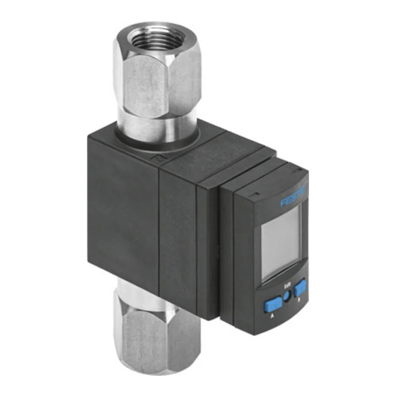
The operating instructions describe the entire function range. The function range is lim ited, depending on the product variant. Overview Display, rotatable Electrical connection B key Fluid connection 1 (input), rotatable Edit button Fluid connection 2 (output), rotatable A key Fig. 1 Control sections and connections Festo – SFAW – 1602a English... -
Page 6: Key Features
0…10 V or 1…5 V or 4…20 mA Electrical connection Plug connector M12, A-coded Electrical accessories +2.5 S Straight socket, 2.5 m cable +5 S Straight socket, 5 m cable Protective devices Safety guard Tab. 1 Overview of variants Festo – SFAW – 1602a English... -
Page 7: Function And Application
Flow rate analogue Q OutB binary T/BDC2 Temperature analogue T OutD Pin 2 binary Q/BDC4 T or Q Volume pulse VP analogue Q/PDV1_2byte Volume recorder V analogue T/PDV2_2byte analogue V/onReq_4byte Fig. 2 SFAW-…PNLK-PNVBA-…: Signal structure Festo – SFAW – 1602a English... -
Page 8: Operating Statuses
– Setting or modification of parameters TEACH mode – Acceptance of the current measured value to determine switching points RECORDER mode – Manual measurement of the accumulated volume Tab. 2 Operating statuses of the SFAW Festo – SFAW – 1602a English... -
Page 9: Switching Outputs
The measured variable that first caused the colour change always appears in the display. The unit and the corresponding output OutA/OutC/OutD flash in the sub display. The display remains red until all switching outputs are in the blue status again. Festo – SFAW – 1602a English... -
Page 10: Volume Pulse
The analogue output signal 0 … 10 V, 1 … 5 V or 4 … 20 mA is assigned to the complete sensing range at the factory. If only part of the sensing range is to be used, the analogue value output can be scaled to this partial range. Festo – SFAW – 1602a English... -
Page 11: Filter
In the SHOW mode, the minimum values and the maximum values for the flow measurement or the temperature measurement are displayed and reset. Switching off the operating voltage resets the minimum and maximum values. Festo – SFAW – 1602a English... -
Page 12: Requirements For Product Use
QUYX, QUYX7 Product category code File number E322346 Considered standards UL 610101, CAN/CSAC22.2 No.610101 UL mark Tab. 5 Only for connection to a NEC/CEC Class 2 supply. Raccorder uniquement a un circuit NEC/CEC Classe 2. Festo – SFAW – 1602a English... -
Page 13: Installation
11 mm 19 mm Min. internal diameter of inlet path 1.1 x D 1.05 x D Typ. inlet path L 10 cm Min. outlet path 5 cm Tab. 7 Minimum requirements for fluid connection Festo – SFAW – 1602a English... -
Page 14: Mechanical Installation
Any mounting position is allowed. The sensor can be installed without mounting accessories or with wall mounting. Max. 0.5 Nm Max. 0.5 Nm Fig. 7 Direct mounting: Fig. 8 Wall mounting (SFAW-…-W-…): hole pattern è Fig. 15 hole pattern è Fig. 16 Festo – SFAW – 1602a English... -
Page 15: Fluid Connection
• Pay attention to the wiring when configuring the switching outputs (è 5.4.4 Changing sensor settings). • Connect sensor. – Consider the maximum permissible line length: 30 m, with IO-Link 20 m. – Consider the maximum tightening torque of the plug connector: 0.5 Nm. Festo – SFAW – 1602a English... - Page 16 1) Observe signal structures (è Fig. 2 and Fig. 3). 2) When using the connecting cable from the electrical accessories (è 1.2 Key features) Tab. 8 Pin allocation Circuit diagrams SFAW-…-PNLK-PNVBA-… SFAW-…-PNLK-PN-VBA-… Tab. 9 Circuit diagrams Festo – SFAW – 1602a English...
-
Page 17: Commissioning
Switching output OutA set [OutC] Switching output OutC selected Switching output OutC set [OutC] [OutB] Switching output OutB selected Switching output OutB set [OutB] [OutD] Analogue output OutD selected [OutD] Switching output OutD set Festo – SFAW – 1602a English... - Page 18 [COLR] Display colour: [bLUE] = Blue, colour change function deactivated [R.ON] = Red, if switching output set [R.OFF] = Red, if switching output not set [200] [PULS] / [MSEC] Width of the volume pulse Festo – SFAW – 1602a English...
- Page 19 Switchover of the analogue output signal at pin 5 between flow and temperature measurement [OFF] [Lock] / [Code] Activation and determination of the security code [OFF] [MASt] Activation of the IO-Link master function for replication of parameters Tab. 11 Festo – SFAW – 1602a English...
-
Page 20: Switch On Sensor (Run Mode)
è The signals active at the outputs are displayed (signal structure è è Fig. 2 and Fig. 3). By pressing the A key or B key, the display can be switched between the measured variables flow rate, volume and temperature (è Fig. 12). Festo – SFAW – 1602a English... -
Page 21: Displaying Parameters (Show Mode)
PULS logic logic COLR FLOW tEMP FLOW tEMP AVER FLOW Measured value indicator (RUN mode) A key or B key Double click A key or B key Fig. 12 Menu structure for SHOW mode Festo – SFAW – 1602a English... -
Page 22: Start Show Mode
If no further keys are pressed, the display remains permanently (no timeout). 2. Press the Edit button. è The value of the filter time constant is changed (650 ms, 1200 ms, 2500 ms). 3. Press A key. è Switch to the RUN mode. Festo – SFAW – 1602a English... -
Page 23: Configure Sensor (Edit Mode)
Unit bin or ANLG COLR tEMP Pin5 Unit ANLG Code Lock MASt Measured value indicator (RUN mode) = Edit button = A key or B key Fig. 13 Menu structure for the EDIT mode Festo – SFAW – 1602a English... - Page 24 1) All parameters of the complete menu structure are listed. Some menu options or setting values are not applicable, depending on the product variant and the selected switching function. 2) The values refer to the respective measuring range. Tab. 12 Adjustable values and factory setting Festo – SFAW – 1602a English...
-
Page 25: Enter The Security Code
8. Select the switching element function with the A key or B key. 9. Press the Edit button. è [COLR] flashes. 10.Select the setting for colour change with the A key or B key. 11.Press the Edit button. è Switch to the RUN mode. Festo – SFAW – 1602a English... -
Page 26: Setting Display Units And Analogue Output
12.Press the Edit button. è [tEMP] / [Unit] flashes. 13.Select the display unit for the temperature measurement with the A key or B key. 14.Press the Edit button. è Switch to the RUN mode. Festo – SFAW – 1602a English... -
Page 27: Changing Sensor Settings
If an error occurs, an error message appears (è 9 Fault clearance). 6. Repeat point 5 if an additional sensor should be parameterised. 7. Press the Edit button. è Switch to the RUN mode. Festo – SFAW – 1602a English... -
Page 28: Teach Switching Points (Teach Mode)
è Switch to the RUN mode. If the RECORDER mode is exited during a volume measurement, the measurement will continue in the background. If the operating voltage is switched off, the measurement is discontinued without the value being saved. Festo – SFAW – 1602a English... -
Page 29: Operation
2. Separate connections from the sensor. 3. Loosen the mountings. If mounted into fixed piping, the sensor can be separated from the fluid connectors through removal of the clips on the back side (è 4.3 Fluid connection). Festo – SFAW – 1602a English... -
Page 30: Fault Clearance
<Value> / [Pin4] [Er21] / [SHRt] Short circuit at the switching • Eliminate short circuit. output pin 4 <Value> / [Pin2] [Er22] / [SHRt] Short circuit at the switching • Eliminate short circuit. output pin 2 Festo – SFAW – 1602a English... -
Page 31: Accessories
[Err] error display to turn red. Accessories Designation Type Wall mounting SAMH-FW-W Fluid connection set SASA-FW-A-… Safety guard SACC-PU-G Clip SAMH-FW-SB Seal SASF-FW-S-E Tab. 14 Accessories Further accessories è www.festo.com/catalogue Festo – SFAW – 1602a English... -
Page 32: Technical Data
400 with filter time constant 150 ms (adjustable) Switch-off time [ms] 300 with filter time constant 150 ms (adjustable) Max. output current [mA] Voltage drop Max. 1.5 Pull-down / pull-up resistor PNP: integrated; NPN: not integrated Inductive protective circuit On hand Festo – SFAW – 1602a English... - Page 33 , US gal, cft, °C, °F Setting range for volume pulse 0.1 … 1999.9 threshold value 0.01 … 199.99 [cft] 0.01 … 199.99 [US gal] 1 … 19999 Hysteresis setting range [% FS] 0 … 90 Festo – SFAW – 1602a English...
- Page 34 1 bit BDC (temperature monitoring) 14 bit PDV (flow measured value) 14 bit PDV (temperature measured value) Service data contents IN 32 bit PDV (volume measured value) è www.festo.com IODD, IO-Link device description Tab. 16 IO-Link Festo – SFAW – 1602a English...
-
Page 35: Hole Patterns And Dimensional Drawings
L5 = 7.3 mm + 0.1 D1 = -N-27 f8 D2 = -N-23 - 0.1 D3 = -N-23 ± 0.1 D4 = -N-30 R = 0.3 W1 = 30° Fig. 17 Dimensional drawing of customer-specific fluid connections Festo – SFAW – 1602a English... - Page 36 Copyright: Festo AG & Co. KG Postfach 73726 Esslingen Germany Phone: +49 711 347-0 Fax: +49 711 347-2144 e-mail: service_international@festo.com Reproduction, distribution or sale of this document or communica tion of its contents to others without express authorization is Internet: prohibited.
Need help?
Do you have a question about the SFAW Series and is the answer not in the manual?
Questions and answers