Festo SOPA Series Operating Instructions Manual
Air gap sensor
Hide thumbs
Also See for SOPA Series:
- Operating instructions manual (80 pages) ,
- Instructions manual (9 pages)

Related Manuals for Festo SOPA Series


Summary of Contents for Festo SOPA Series
- Page 1 Luftspaltsensor Air gap sensor SOPA-... Bedienungs- anleitung Operating instructions 756208 1202a...
- Page 2 ........... . . Festo – SOPA-... – 1202a...
-
Page 3: Table Of Contents
............Festo – SOPA-... – 1202a Deutsch... - Page 4 ........... . Festo – SOPA-... – 1202a Deutsch...
-
Page 5: Produktbeschreibung
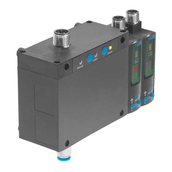
Steuermodul (optional) Gewindehülse (M4) Sensormodul (in Verbindung mit Blindstopfen (M7) Steuermodul max. 4 Module zulässig) Schildträger Stecker für elektrischen Anschluss Adapterplatte für Wandmontage Display Stecker für elektrischen Anschluss Befestigungsschieber Fig. 1 Mechanik und elektrische Anschlüsse Festo – SOPA-... – 1202a Deutsch... - Page 6 Taste – Sense (Messluft) Entlüftungsschraube (Schlüsselweite 14) EDIT-Knopf Druckluftanschluss für Speisedruck B-Taste Status-LED (gelb) – Sense (Messluft) A-Taste Status-LED (gelb) – Clean (Ausblasluft) 1) Nur bei Produktvarianten mit Handhilfsbetätigung (SOPA-C-...-H) Fig. 2 Bedienteile und pneumatische Anschlüsse Festo – SOPA-... – 1202a Deutsch...
-
Page 7: Merkmale
Verbindungsleitung mit Dose gerade, Kabellänge 5 m Verbindungsleitung mit Dose gewinkelt, Kabellänge 2,5 m Verbindungsleitung mit Dose gewinkelt, Kabellänge 5 m 1) Option Handhilfsbetätigung nicht wählbar 2) Anzahl der Verbindungsleitungen abhängig von der Anzahl der Module Tab. 1 Variantenübersicht Festo – SOPA-... – 1202a Deutsch... -
Page 8: Funktion Und Anwendung
Messdüse, ist der Luftspalt sehr klein und wenig Luft strömt aus. Entfernt sich das Objekt, wird der Luftspalt größer und mehr Luft strömt aus. Die Durchflussänderung wird von den Sensormodulen erfasst, in einen abstandskorrelierten Wert umgewandelt und angezeigt (Geschwindigkeits- messverfahren mit Ejektor). Festo – SOPA-... – 1202a Deutsch... -
Page 9: Betriebszustände
Wert und den Speisedruck. EDIT-Modus – Einstellen oder Ändern der Parameter für den Luftspaltsensor (Schaltausgänge, Displayanzeige). TEACH-Modus – Teachen der Schaltpunkte für den abstandskorrelierten Werte (Übernahme des aktuellen Wertes als Schaltschwelle). Tab. 2 Betriebszustände des SOPA Festo – SOPA-... – 1202a Deutsch... -
Page 10: Funktionsumfang
– Jedem Binärsignal kann die Schaltelementfunktion Öffner (NC) oder Schließer (NO) zugeordnet werden. – Für die Binärsignale Out A und Out B können Schaltpunkt (SP) und Hysterese (HY) eingestellt werden. Für Out C sind nur die Schaltpunkte einstellbar. Festo – SOPA-... – 1202a Deutsch... - Page 11 – Oberer Rückschaltpunkt = Schaltpunkt + Hysterese – Unterer Rückschaltpunkt = Schaltpunkt – Hysterese Bereich, in dem Schaltsignale bei Schaltabstand Schwankungen um den Schaltpunkt (SP) Messdüse unterdrückt werden Objekt Schaltpunkt Hysterese Fig. 6 Erfassungsbereich mit Schaltpunkten Festo – SOPA-... – 1202a Deutsch...
-
Page 12: Grafische Abstandsüberwachung
Schaltbereichs Abstand < 0,4 x Schaltpunkt Abstand < 0,2 x Schaltpunkt Leuchtet immer Betriebszustandsanzeige 1) Der Schaltpunkt von Out A und Out B liegt zwischen Segment 5 und 6 Tab. 4 Balkenanzeige im RUN-Modus Festo – SOPA-... – 1202a Deutsch... -
Page 13: Fehlimpulsunterdrückung - Parameter Optionen
Modus) eingegeben werden. 2.3.6 Min/Max Werte Im SHOW-Modus können die Min/Max Werte für die Speisedrucküberwachung und die Abstandsüber- wachung angezeigt und zurück gesetzt werden, Kapitel 5.5. Hinweis Das Ausschalten der Versorgungsspannung setzt die Min/Max Werte zurück. Festo – SOPA-... – 1202a Deutsch... -
Page 14: Voraussetzungen Für Den Produkteinsatz
Bei ungeeigneter Anordnung der Messdüsen oder ungeeignetem Verlauf der Druckluft- leitungen können Fremdkörper in die Sensormodule gelangen und eine Fehlfunktion auslösen oder das Gerät beschädigen. • Berücksichtigen Sie die Umgebungsbedingungen am Einsatzort durch konstruktive Maßnahmen – z. B. durch geeignete Messdüsenanordnung. Festo – SOPA-... – 1202a Deutsch... - Page 15 Entlüftung in die Umgebung erlauben ( Fig. 8). • Halten Sie die zulässigen Schlauchlängen zwischen Sensormodul und Messdüse ein ( Technische Daten, Kapitel 11). Zurückversetzte Messdüse Entlüftung Unzulässig Luftkanal (Beispiel) Messdüse Abstand 30...60 µm Fig. 8 Messdüsenanordnung Festo – SOPA-... – 1202a Deutsch...
- Page 16 Note that, when more than one power supply or isolating device is used, connection in parallel is not permitted. UL approval information Product category code NRNT2 (USA) or NRNT8 (Canada) File number E253738 Considered standards UL 508, 17th edition, C22.2 No.14-2005 UL mark Tab. 6 UL approval information Festo – SOPA-... – 1202a Deutsch...
-
Page 17: Einbau
Platzieren Sie das Gerät entsprechend der spezifizierten Schlauchlängen in die Nähe der • Messdüsen (Schlauchlänge 0,5...8 m). Hutschienenmontage: • Hängen Sie den SOPA in die Hutschiene ein und drücken Sie ihn an, bis die Befestigungsschie- ber einrasten. Fig. 10 Hutschienenmontage Festo – SOPA-... – 1202a Deutsch... - Page 18 1. Montieren Sie auf den Speisedruckanschluss 1 oder 2 die Verschraubung mit Gewinde M7. Max. Gewindelänge: 5,5 mm. 2. Verschließen Sie den gegenüberliegenden An- schluss mit dem Blindstopfen M7. Schlüsselweite SW 3 mm, handfest festziehen. Fig. 13 Sensormodule anbringen Festo – SOPA-... – 1202a Deutsch...
-
Page 19: Pneumatisch
(über Entlüftungsschraube oder Differenzdruck-Regelventil (LRLL-1/8-QS-6). Verschmutzung der Messdüsen in Stillstandszeiten vermeiden Die Entlüftungsschraube ( Fig. 2) kann entfernt und dieser Anschluss bei abgeschalteter Hauptluft- und ggf. Energieversorgung zur Einspeisung von Spülluft genutzt werden. Festo – SOPA-... – 1202a Deutsch... -
Page 20: Elektrischer Anschluss
– SOPA-...-...-2P: Versorgungsspannung für PNP-Eingänge Signaleingang Messluft einschalten (Sense) Schwarz (BK) n.c = frei (not connected) Grau (GY) 1) Bei Verwendung der Verbindungsleitung aus dem elektrischen Zubehör Kapitel 1.2 Merkmale Tab. 7 Pin-Belegung Steuermodul Festo – SOPA-... – 1202a Deutsch... - Page 21 Schaltausgang für Out A Schwarz (BK) n.c = frei (not connected) Grau (GY) 1) Bei Verwendung der Verbindungsleitung aus dem elektrischen Zubehör Kapitel 1.2 Merkmale Tab. 9 Pin-Belegung Sensormodul Sensormodul SOPA-...-...-...-2P-M12-... SOPA-...-...-...-2N-M12-... Tab. 10 Schaltbilder Sensormodul Festo – SOPA-... – 1202a Deutsch...
-
Page 22: Inbetriebnahme
– Die Balkenanzeige für In A ist immer aktiv. – Die Balkenanzeige für In B ist nur aktiv, wenn dem Schaltausgang an Pin 2 das Binärsignal Out B zugeordnet ist. Tab. 11 Symbolik auf dem Display Festo – SOPA-... – 1202a Deutsch... -
Page 23: Balkenanzeige Auf Dem Display
[Option] blinkt. – Spezialmenü geöffnet. – 7-Segmentanzeige zeigt die eingestellte Option. Markierte Segmente leuchten – EDIT-Modus aktiv. und [Lock] blinkt. – Spezialmenü geöffnet. – 7-Segmentanzeige zeigt den Sicherheitscode. Tab. 12 Spezielle Balkenanzeigen auf dem Display Festo – SOPA-... – 1202a Deutsch... -
Page 24: Symbolik Zur Darstellung Der Menüstruktur
– die grafische Darstellung (Balkenanzeige) der abstandskorrelierten Werte bezogen auf die jewei- ligen Schaltpunkte der Binärsignale Out A bzw. Out B und – die Signalzustände der Schaltausgänge Out A, Out B, Out C (gesetzt, nicht gesetzt). Ein blinkender Wert bedeutet, dass der Messbereich überschritten ist. Festo – SOPA-... – 1202a Deutsch... -
Page 25: Info- / Show-Modus
Kapitel 11). 2. Schalten Sie die Betriebsspannung ein. Der SOPA befindet sich im RUN-Modus. 3. Prüfen Sie die Einstellungen des SOPA ( Kapitel 5.5). INFO- / SHOW-Modus Fig. 15 Menüstruktur INFO-Modus / SHOW-Modus Festo – SOPA-... – 1202a Deutsch... - Page 26 Wird kein weitere Tastendruck vorgenommen, bleibt diese Anzeige dauerhaft bestehen (kein Timeout). Die Anzeige der Minimalwerte und Maximalwerte kann durch Drücken des Edit-Knopfes zurückgesetzt werden. 3. Drücken Sie die A-Taste, B-Taste oder C-Taste erneut. Der SOPA wechselt in den RUN-Modus. Festo – SOPA-... – 1202a Deutsch...
-
Page 27: Edit-Modus
– das Spezialmenü [SPEC]. Warnung Abhängig von der Funktionalität der Maschine/Anlage kann die Manipulation von Signalzuständen schwere Personenschäden verursachen. • Berücksichtigen Sie, dass das Ändern des Schaltverhaltens der Ausgänge im EDIT-Modus sofort wirksam wird. Festo – SOPA-... – 1202a Deutsch... -
Page 28: Schaltverhalten Der Binärsignale Einstellen
Prüfen Sie im Probelauf durch Variieren des Abstandes, ob der SOPA wie gewünscht schaltet. Hinweis Zur Einstellung der Abstandsüberwachung für Out B wählen Sie in Punkt 3 [Out B] und setzen dann die Einstellprozedur wie oben beschrieben fort. Festo – SOPA-... – 1202a Deutsch... - Page 29 Der SOPA wechselt in den RUN-Modus. Prüfen Sie im Probelauf durch variieren des Speisedrucks, ob der SOPA wie gewünscht schaltet. Empfehlung: Teachen Sie den Wert für Out A neu, nachdem Sie die Schaltpunkte für Out C geändert haben. Festo – SOPA-... – 1202a Deutsch...
-
Page 30: Spezialmenü [Spec] Einstellen
Bei vergessenem Sicherheitscode muss der SOPA auf Werkseinstellung zurückgesetzt werden ( pitel 6). 11.Wählen Sie mit den A-/B-Tasten zwischen einem inaktiven Sicherheitscode (OFF) oder einem ma- ximal 4-stelligen Sicherheitscode. 12.Drücken Sie den Edit-Knopf, um die Auswahl zu bestätigen. Der SOPA wechselt in den RUN-Modus. Festo – SOPA-... – 1202a Deutsch... -
Page 31: Teach-Modus
3. Stellen Sie den Sicherheitscode mit den A-/B-Tasten ein. 4. Drücken Sie den Edit-Knopf. [Out A] und [TeachIn] blinken.Der in Schritt 2 zwischengespeicherte Wert wird als Schaltpunkt übernommen. Der SOPA wechselt in den RUN-Modus. Festo – SOPA-... – 1202a Deutsch... - Page 32 1. Schalten Sie die Betriebsspannung aus. 2. Drücken Sie gleichzeitig alle drei Einstellelemente (A-Taste + B-Tasten + Edit-Knopf ) und halten sie gedrückt. 3. Schalten Sie die Betriebsspannung wieder ein. Das Sensormodul schaltet im RUN-Modus ein. Festo – SOPA-... – 1202a Deutsch...
- Page 33 SOPA von außen reinigen 1. Schalten Sie die Betriebsspannung ab. 2. Schalten Sie die Druckluft ab. 3. Reinigen Sie den SOPA von außen. Zulässige Reinigungsmedien sind Seifenlauge (max. +60 °C), Waschbenzin und alle werkstoffscho- nenden Medien. Festo – SOPA-... – 1202a Deutsch...
- Page 34 3. Trennen Sie die Anschlüsse vom Steuermodul und den Sensormodulen. Fig. 18). 4. Bauen Sie das Gerät aus ( Wandmontage / Hutschienenbefestigung Plattenmontage Gerät anheben Schrauben lösen Gerät nach vorn wegkippen Gerät abnehmen Fig. 18 SOPA ausbauen Festo – SOPA-... – 1202a Deutsch...
- Page 35 ( Kapitel 6.2) senen Messdüsen Kein Betriebsbereitssignal bei Kein Druckabbau an der Messdüse Differenzdruck-Regelventil Verwendung eines Differenz- einstellen ( Kapitel 6.2) druck-Regelventils 1) Wenn Sicherheitscode nicht mehr auffindbar. Tab. 15 Störungsbeseitigung Festo – SOPA-... – 1202a Deutsch...
- Page 36 Zulassung C-Tick, c UL us – Recognized (OL) CE-Zeichen (Konformitätserklärung nach EU-EMV-Richtlinie www.festo.com) Werkstoff-Hinweis RoHS-konform Eingangssignal / Messelement Messgröße Abstand Messprinzip pneumatisch Erfassungsbereich [µm] 20...200 Betriebsdruck [bar] 4...7 Speisedruck [bar] 0,8...1,6 Max. Überlastdruck [bar] Festo – SOPA-... – 1202a Deutsch...
- Page 37 Anzeigebereich In C ( Speisedruck ) [bar] 0...2 Ausgang, weitere Daten Kurzschlussfestigkeit ja (taktend) Überlastfestigkeit vorhanden Elektronik Bemess.-Betriebsspannung DC Betriebsspannung DC 22,8…26,4 15,0…30,0 Max. Leerlaufstrom [mA] Verpolungsschutz für alle elektrischen Anschlüsse Elektromechanik Elektrischer Anschluss Stecker, M12x1, 4-polig Max. Leitungslänge Festo – SOPA-... – 1202a Deutsch...
- Page 38 5 g Beschleunigung bei 60 … 150Hz 1) Es darf sich kein Kondenswasser im Sensormodul sammeln können 2) Steckverbindung für Schlauchaußendurchmesser 6 mm 3) Bei Auswahl des Merkmals …-W-.. 4) Nicht einstellbar Tab. 18 SOPA: Technische Daten Festo – SOPA-... – 1202a Deutsch...
- Page 39 Typische Ansprechzeit t in Abhängigkeit des Erfassungswertes Abstand x nach Einschalten der Messluft (Messdüse 2 mm) Schlauchlänge in [m] 0,5 m x [µm] Fig. 20 Typische Ansprechzeit t in Abhängigkeit des Erfassungswertes Abstand x nach Abschalten der Ausblasluft (Messdüse 2 mm) Festo – SOPA-... – 1202a Deutsch...
- Page 40 Erweiterter Erfassungsbereich – nur bei Typ SOPA-M1 möglich; unter 20 µm in Verbidnung mit zurückversetzten Messdüsen über 200 µm mit geeignetem Präzisionsdruckregler Fig. 22 Wiederholgenauigkeit des Schaltpunktes [±µm] in Abhängigkeit des Schaltpunktabstandes x (Messdüse 2 mm) Festo – SOPA-... – 1202a Deutsch...
- Page 41 Lochbilder Adapterplatte SXE3-W Abstandsmaß, abhängig von der Anzahl der verwendeten Sensormodule ( Tab. 19) Fig. 23 Lochbilder Adapterplatte SXE3-W Anzahl der Sensormodule Maß X [mm] 83,5 104,0 124,5 145,0 Fig. 23 Tab. 19 Abmessungen Maß X Festo – SOPA-... – 1202a Deutsch...
- Page 42 2. Drücken Sie zuerst die A-Taste und dann zusätzlich den Edit-Knopf. [Out A] und [TeachIn] blinken. 3. Lassen Sie beide Tasten los. Der Wert wird als Schaltpunkt übernommen oder [Lock] blinkt (Sicherheitssperre aufheben Kapitel 5.7). Das Sensormodul wechselt in den RUN-Modus. Festo – SOPA-... – 1202a Deutsch...
- Page 43 ............. Festo – SOPA-... – 1202a English...
- Page 44 ............Festo – SOPA-... – 1202a English...
-
Page 45: Product Description
Blanking plug (M7) control module) Inscription label holder Plug for electrical connection Adapter plate for wall mounting Display Plug for electrical connection Fig. 1 Mechanical and electrical connections Festo – SOPA-... – 1202a English... - Page 46 B button Status LED (yellow) – Sense (measuring air) A button Status LED (yellow) – Clean (exhaust air) 1) Only on product variants with manual override (SOPA-C-…-H) Fig. 2 Operating elements and pneumatic connections Festo – SOPA-... – 1202a English...
-
Page 47: Features
Connecting cable with angled socket, cable length 2.5 m Connecting cable with angled socket, cable length 5 m 1) Optional manual override not selectable 2) Number of connecting cables dependent on the number of modules Tab. 1 Overview of variants Festo – SOPA-... – 1202a English... -
Page 48: Function And Application
The change in flow rate is detected by the sensor modules, converted into a distance-correlated value and displayed (speed measuring method with ejector). Festo – SOPA-... – 1202a English... -
Page 49: Operating States
– Setting or alteration of the parameters for the air gap sensor (switching outputs, display). TEACH mode – Teaching-in of the switching points for the distance-correlated values (transfer of the current value as the trigger level). Tab. 2 SOPA operating states Festo – SOPA-... – 1202a English... -
Page 50: Functional Range
– The switching point (SP) and hysteresis (HY) can be set for the binary signals Out A and Out B. Only the switching points can be adjusted for Out C. Festo – SOPA-... – 1202a English... - Page 51 – Lower reset point = switching point – hysteresis Range in which switching signals are Switching distance suppressed in the event of fluctuations Measuring nozzle about the switching point (SP) Object Switching point Hysteresis Fig. 6 Sensing range with switching points Festo – SOPA-... – 1202a English...
-
Page 52: Graphic Distance Monitoring
Distance < 0.2 x switching point Is always lit up Operating status display 1) The switching point of Out A and Out B is between segment 5 and 6 Tab. 4 Bar graph in the RUN mode Festo – SOPA-... – 1202a English... -
Page 53: Spurious Pulse Suppression - Parameter Options
2.3.6 Min/max values The min/max values for supply pressure monitoring and distance monitoring can be displayed and reset in the SHOW mode, Chapter 5.5. Note Switching off the power supply resets the min/max values. Festo – SOPA-... – 1202a English... -
Page 54: Requirements For Product Use
• Take the ambient conditions at the location of use into consideration by means of suitable design measures – for example a suitable arrangement of the measuring nozzles. Festo – SOPA-... – 1202a English... - Page 55 • Observe the permissible tube lengths between the sensor module and measuring nozzle Technical Data, Chapter 11). Recessed measuring nozzle Exhaust Not permitted Air duct (example) Measuring nozzle Distance 30 … 60 µm Fig. 8 Measuring nozzle configuration Festo – SOPA-... – 1202a English...
- Page 56 Note that, when more than one power supply or isolating device is used, connection in parallel is not permitted. UL approval information Product category code NRNT2 (USA) or NRNT8 (Canada) File number E253738 Considered standards UL 508, 17 edition, C22.2 No.14-2005 UL mark Tab. 6 UL approval information Festo – SOPA-... – 1202a English...
-
Page 57: Installation
Position the device in close proximity to the measuring nozzles in accordance with the • specified tube lengths (tube length 0.5 … 8 m). H-rail mounting: • Hang the SOPA on the H-rail and press it until the mounting tabs engage in place. Fig. 10 H-rail mounting Festo – SOPA-... – 1202a English... - Page 58 1. Mount the threaded M7 fitting onto the supply pressure connection 1 or 2. Max. thread length: 5,5 mm. 2. Seal the opposite connection with the M7 blanking plug. A/F 3 mm, tighten by hand. Fig. 13 Attaching sensor modules Festo – SOPA-... – 1202a English...
-
Page 59: Pneumatic Spring
Avoiding contamination of the measuring nozzles during downtimes The bleed screw ( Fig. 2) can be removed and this connection used with a deactivated main air supply and power supply, if necessary, to feed purge air. Festo – SOPA-... – 1202a English... -
Page 60: Electrical Connection
Switch on signal input measuring air (Sense) Black (BK) n.c. = not connected Grey (GY) 1) With use of the connecting cable from the electrical accessories Chapter 1.2 Characteristics Tab. 7 Pin allocation for control module Festo – SOPA-... – 1202a English... - Page 61 (GY) 1) With use of the connecting cable from the electrical accessories Chapter 1.2 Characteristics Tab. 9 Pin allocation for sensor module Sensor module SOPA-…-…-…-2P-M12-… SOPA-…-…-…-2N-M12-… Tab. 10 Circuit diagrams for sensor module Festo – SOPA-... – 1202a English...
-
Page 62: Commissioning
– The bar graph for In A is always active. – The bar graph for In B is only active if the binary signal Out B is assigned to the switching output at Pin 2. Tab. 11 Symbols on the display Festo – SOPA-... – 1202a English... -
Page 63: Bar Graph On The Display
– 7-segment display shows the set option. Selected segments illuminate and – EDIT mode active. [Lock] flashes. – Special menu opens. – 7-segment display shows the security code. Tab. 12 Special bar graphs on the display Festo – SOPA-... – 1202a English... -
Page 64: Symbols For Representing The Menu Structure
Out A and/or Out B and – the signal states of the switching outputs Out A, Out B, Out C (set, not set). A flashing value indicates that the measuring range has been exceeded. Festo – SOPA-... – 1202a English... -
Page 65: Info/Show Mode
Technical Data, Chapter 11). 2. Switch on the operating voltage. The SOPA is in the RUN mode. 3. Check the SOPA settings ( Chapter 5.5). INFO/SHOW mode Fig. 15 Menu structure for the INFO mode/SHOW mode Festo – SOPA-... – 1202a English... - Page 66 (no timeout). The display of the minimum and maximum values can be reset by pressing the Edit button. 3. Press button A, button B or button C again. The SOPA switches to the RUN mode. Festo – SOPA-... – 1202a English...
-
Page 67: Edit Mode
Depending on the functioning of the machine/system, manipulation of signal states may cause serious personal injury. • Note that if the switching status of the outputs is modified in the EDIT mode, the new status will be effective immediately. Festo – SOPA-... – 1202a English... -
Page 68: Setting The Switching Characteristic Of Binary Signals
Conduct a test run and vary the distance to check whether the SOPA switches as desired. Note To set the distance monitoring function for Out B, select [Out B] at point 3 and then continue the setting procedure as described above. Festo – SOPA-... – 1202a English... - Page 69 Conduct a test run and vary the supply pressure to check whether the SOPA switches as desired. Recommendation: Re-teach the value for Out A after you have changed the switching points for Out C. Festo – SOPA-... – 1202a English...
-
Page 70: Setting Special Menu [Spec]
Chapter 6). 11.Use the A/B buttons to select between an inactive security code (OFF) or a maximum 4-digit security code. 12.Press the Edit button to confirm the selection. The SOPA switches to the RUN mode. Festo – SOPA-... – 1202a English... -
Page 71: Teach Mode
4. Press the Edit button. [Out A] and [TeachIn] flash. The value that is stored in the buffer at step 2 is transferred as the switching point. The SOPA switches to the RUN mode. Festo – SOPA-... – 1202a English... - Page 72 2. Press all three setting elements (A button + B button + Edit button) simultaneously and hold them down. 3. Switch the operating voltage back on. The sensor module switches to the RUN mode. Festo – SOPA-... – 1202a English...
- Page 73 1. Switch off the operating voltage. 2. Switch off the compressed air. 3. Clean the SOPA from the outside. Permitted cleaning agents are soap suds (max. +60 °C), petroleum ether and all non-abrasive agents. Festo – SOPA-... – 1202a English...
- Page 74 3. Disconnect the connections for the control module and the sensor modules. Fig. 18). 4. Disassemble the device ( Wall mounting/H-rail mounting Plate mounting Lift the device Loosen the screws Tilt the device forwards Remove the device Fig. 18 Disassembling the SOPA Festo – SOPA-... – 1202a English...
- Page 75 No pressure reduction for the Adjust the differential signal when using a measuring nozzle pressure regulating valve differential pressure Chapter 6.2) regulating valve 1) If the security code can no longer be found. Tab. 15 Troubleshooting Festo – SOPA-... – 1202a English...
- Page 76 Note on materials Conforms to RoHS Input signal/measuring element Measured variable Distance Measuring principle pneumatic Sensing range [µm] 20 … 200 Operating pressure [bar] 4 … 7 Supply pressure [bar] 0.8 … 1.6 Festo – SOPA-... – 1202a English...
- Page 77 Rated operating voltage DC Operating voltage DC 22.8 … 26.4 15.0 … 30.0 Max. idle current [mA] Reverse polarity protection For all electrical connections Electromechanical components Electrical connection Plug, M12x1, 4-pin Max. line length Festo – SOPA-... – 1202a English...
- Page 78 1) No condensed water should be able to accumulate in the sensor module 2) Plug connector for outer diameter of tubing 6 mm 3) When selecting feature …-W-… 4) Not adjustable Tab. 18 SOPA: Technical data Festo – SOPA-... – 1202a English...
- Page 79 (measuring nozzle: 2 mm) Tube length in [m] 0.5 m x [µm] Fig. 20 Typical response time t as a function of distance x after switching off the exhaust air (measuring nozzle: 2 mm) Festo – SOPA-... – 1202a English...
- Page 80 20 µm in conjunction with set-back measuring nozzles over 200 µm with a suitable precision pressure regulator Fig. 22 Repetition accuracy of the switching point [±µm] as a function of the switching point distance (measuring nozzle: 2 mm) Festo – SOPA-... – 1202a English...
- Page 81 Distance dimension, dependent on the number of sensor modules used ( Tab. 19) Fig. 23 Hole patterns for adapter plate SXE3-W Number of sensor modules Dimension X [mm] 83.5 104.0 124.5 145.0 Fig. 23 Tab. 19 Dimensions X Festo – SOPA-... – 1202a English...
- Page 82 2. First press the A button and then also the Edit button. [Out A] and [TeachIn] flash. 3. Release both buttons. The value is transferred as the switching point or [Lock] flashes (release security lock Chapter 5.7). The sensor module switches to the RUN mode. Festo – SOPA-... – 1202a English...
- Page 83 SOPA-... Festo – SOPA-... – 1202a English...
- Page 84 Copyright: Festo AG & Co. KG Postfach D-73726 Esslingen Phone: +49 711 347 0 Weitergabe sowie Vervielfältigung dieses Dokuments, Verwertung Fax: und Mitteilung seines Inhalts sind verboten, soweit nicht aus- +49 711 347 2144 drücklich gestattet. Zuwiderhandlungen verpflichten zu Schaden- ersatz.
Need help?
Do you have a question about the SOPA Series and is the answer not in the manual?
Questions and answers