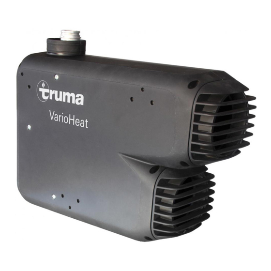
Truma VarioHeat Operating Instructions Manual
Hide thumbs
Also See for VarioHeat:
- Operating instructions manual (100 pages) ,
- Installation instructions manual (68 pages) ,
- Product information (8 pages)
Table of Contents
Advertisement
Advertisement
Table of Contents
Troubleshooting

Summary of Contents for Truma VarioHeat
- Page 1 Truma VarioHeat Operating instructions Page 2 To be kept in the vehicle!
-
Page 2: Table Of Contents
Room temperature sensor ..........6 sion of liquefied gas in the event of an accident (according Truma CP plus VarioHeat digital control panel ... 6 to UN-ECE regulation 122). Intended use ................6 Safety instructions .............. -
Page 3: A Safe Operating Environment
– Deactivate the time switch. – Switch the heater off on the control panel. – Make sure that the appliances definitely cannot be switched on via the Truma App. Danger of fire / explosion during refuel- ling. The appliance must not be operated during refuelling: –... -
Page 4: Obligations Of The Operator / Vehicle Owner
For vehicles, we recommend the Truma MonoControl CS gas pressure regula- The vehicle owner is responsible for cor- tion system and the Truma DuoComfort / rect operation of the appliance. DuoControl CS gas pressure regulation sys- tem for two-cylinder gas systems. -
Page 5: Operation While Driving
For heating while driving, the UN ECE regula- tion 122 stipulates a safety shut-off device to prevent the uncontrolled escape of gas in the event of an accident. The Truma MonoControl CS gas pressure regulation system fulfils this requirement. National regulations and rules must be followed. -
Page 6: Operating Instructions
The Truma CP plus VarioHeat control panel is used to control with the warning information, which is enclosed with the ap- and monitor a Truma VarioHeat heater and / or a Truma air pliance, in a location in the vehicle where it is clearly visible to conditioning system. -
Page 7: Display And Control Elements
In order to perform the initial start-up, the following steps are required: – Switch on power supply. 12 V direct voltage for the Truma CP plus VarioHeat and Truma VarioHeat control panel, or the 230 V mains voltage for the air conditioning systems. -
Page 8: Functions
Functions Select fan level The functions in the menu bars (3, 4) of the Truma CP plus VarioHeat control panel are selectable in any order. The oper- With connected heating / air conditioning system ating parameters are shown on the status bar (2) and on the displays (5, 6). -
Page 9: Set Time Switch
(OFF). Select fan level – Select desired fan level with rotary push button. – Switch off the heater at the Truma CP plus VarioHeat con- – Tap the rotary push button to confirm the value. trol panel. – When air conditioning systems are being operated, the time switch of the Truma CP plus VarioHeat control... -
Page 10: Switch Lighting On / Off
– Select required function with rotary push button. Presetting: °C (Celsius). 3. Changing the background lighting 1 – 5 – Switch lighting on. Change the background lighting of the Truma CP plus VarioHeat Brightness selectable in 5 levels. control panel in 10 increments. – Switch lighting off. -
Page 11: Special Displays
Other connected appliances can be operated. Fault Figure 28 In the event of a fault, the Truma CP plus VarioHeat control panel Icon appears only in conjunction with a Truma air condi- immediately jumps to the “Fault” menu level and displays the tioning system. -
Page 12: Maintenance
Maintenance Switching off The Truma CP plus VarioHeat control panel is maintenance- Set the rotary switch (b) to the centre (d). If the heater is free. In order to clean the front panel, use a damp, non-scour- turned off after heating, the fan may still run to utilise the re- ing cloth. -
Page 13: Technical Data, Heater
Technical data, heater Dimensions ( all dimensions in mm) Determined in accordance with EN 624 and/or Truma test conditions Gas type Liquefied gas (propane / butane) Operating pressure 30 mbar (see type plate) Rated heat output (gas consumption) Truma VarioHeat eco 1300 W (100 g/h) / 2800 W (220 g/h) -
Page 14: Manufacturer's Warranty (European Union)
Truma or if the Truma control unit (e.g. Truma CP plus or Truma iNet Box) has not been exclusively used for controlling... -
Page 15: Troubleshooting Guide, Truma Varioheat
Troubleshooting guide, Truma VarioHeat Fault Cause Remedy Flame not recognised: # 16 – Gas cylinder or quick-acting valve in the gas – Check gas supply and open valves supply line closed – Gas pressure regulation system iced up – Use EisEx regulator heater –... -
Page 16: Troubleshooting Guide, Truma Varioheat
Troubleshooting guide, Truma VarioHeat Flashing code on the analog CP classic control panel Flashing sequence - On / Off 0.5 seconds Pause between flashing sequence 5 seconds Fault Cause Remedy LEDs do not light up, – Automatic restart is blocked, e.g. - Page 17 Should problems occur, please contact the Truma Service Centre or one of our authorised service partners (see www.truma.com). In order to avoid delays, please have the unit model and serial number ready (see type plate). Typenschild Truma Gerätetechnik GmbH & Co. KG Service Wernher-von-Braun-Straße 12...


