
Related Manuals for Cardinal 201

Summary of Contents for Cardinal 201
- Page 1 Model 201 Weight Transmitter Installation, Technical and Operation Manual (Includes 201ADMIX Weight-Based Admix Dispensing System)
-
Page 3: Precautions
Introduction Thank you for selecting and purchasing the Cardinal Model 201 Weight Transmitter. The Model 201 was built with quality and reliability and incorporates the latest in digital technology and innovative features for the weighing industry. Configuration and upgrades can easily be performed in the field, while still maintaining the rigid control the most demanding installations require. - Page 4 Model 201 Installation & Technical FCC Compliance Statement This equipment generates uses and can radiate radio frequency and if not installed and used in accordance with the instruction manual, may cause interference to radio communications. It has been tested and found to comply with the limits for a Class A...
-
Page 5: Table Of Contents
Model 201 Installation & Technical Table of Contents PRECAUTIONS ....................... I 1. SPECIFICATIONS ...................... 1 1.1 Standard Features ....................2 1.2 Optional Features ....................2 1.3 Approvals ......................2 2. PRECAUTIONS ......................3 2.1 Static Electricity ....................3 3. INSTALLATION ......................5 3.1 Site Preparation Requirements ................ - Page 6 Model 201 Installation & Technical 5. WEIGHT TRANSMITTER SETUP (Non-Metrological Parameters) ....... 41 5.1 Accessing Non-Metrological Parameters ............41 5.2 Set Date and Time ..................... 43 5.3 Event Counter ....................45 5.4 Consecutive Number and Accumulators ............47 5.5 Preferences ......................49 5.6 Serial Port ......................
- Page 7 Model 201 Installation & Technical 12. 201 ADMIX SYSTEM .................... 127 12.1 Introduction ....................127 12.2 Setup and Configuration ................127 12.3 Web Page Configuration ................132 12.4 Operation ....................... 136 12.5 Communication Port Control ................137 13. LEAD AND WIRE SECURITY SEAL INSTALLATION ......... 139 14.
-
Page 9: Specifications
Model 201 Installation & Technical 1. SPECIFICATIONS Power Requirements: 12-24 VDC @ 6w Listed Accessory: The weight transmitter is intended to be used with Listed Information Technology Equipment. IP-20 DIN Rail 35mm, mounted in customers’ Enclosure Rating: enclosure with optional remote display mounting. -
Page 10: Standard Features
Model 201 Installation & Technical Analog Input: Software selectable Non-isolated 0-10 VDC or 4-20mA DC Analog Output: (1) Non-isolated 0-10 VDC output (12 bit, 2k ohm min.) (1) Non-isolated 4-20mA DC output (12 bit, 450 ohm max.) 1.1 Standard Features... -
Page 11: Precautions
Model 201 Installation & Technical 2. PRECAUTIONS 2.1 Static Electricity CAUTION! This device contains static sensitive circuit cards and components. Improper handling of these devices or printed circuit cards can result in damage to or destruction of the component or card. Such actual and/or consequential damage IS NOT covered under warranty and is the responsibility of the device owner. - Page 12 Model 201 Installation & Technical 8400-M117-O1 Rev D Page 4...
-
Page 13: Installation
Model 201 Installation & Technical 3. INSTALLATION 3.1 Site Preparation Requirements The Cardinal Model 201 Weight Transmitter is a precision weight- measuring instrument. As with any precision instrument, it requires an acceptable environment to operate at peak performance and reliability. -
Page 14: Electrical Power
3.1.2 Electrical Power The Model 201 Weight Transmitter has been designed to operate from 12 to 24 VDC @ 6W. The weight transmitter is intended to be used with Listed Information Technology Equipment. -
Page 15: Electrical Noise Interference
Model 201 Installation & Technical 3.1.3 Electrical Noise Interference To prevent electrical noise interference, make certain all other branch circuits for use with air conditioning and heating equipment, lighting or other equipment with heavily inductive loads, such as welders, motors and solenoids are on circuits separate from the weight transmitter. -
Page 16: Mounting
The Model 201 Weight Transmitter is built with a spring-loaded IP20 DIN Rail mounting clip that can be very easily attached and detached from the rail. When on the rail, the clip "grips" the rail on both the top and bottom lips of the rail. -
Page 17: Connections
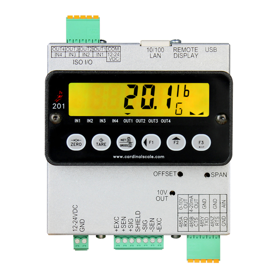
Model 201 Installation & Technical 3.3 Connections P7 - Power P8 - Load Cell Figure No. 2A P9 - Serial & Analog I/O REMOTE Figure No. 2B DISPLAY ISO I/O Enclosure Silkscreen 8400-M117-O1 Rev D Page 9... - Page 18 Model 201 Installation & Technical 8400-M117-O1 Rev D Page 10...
-
Page 19: Load Cell Connections
Model 201 Installation & Technical 3.4 Load Cell Connections WARNING! Disconnect any external load cell power supply before connecting load cells to the weight transmitter. Failure to do so will result in permanent damage to the weight transmitter. 3.4.1. The LOAD CELL wires are to be connected to the P8 terminal block on the bottom panel of the weight transmitter. -
Page 20: Load Cell Connections With Over 30 Feet Of Cable
Model 201 Installation & Technical 3.5 Load Cell Connections with Over 30 Feet of Cable For installations with over 30 feet of cable between the weight transmitter and the load cells, sense wires should be used. The sense wires must be connected between the +SENS, -SENS... -
Page 21: Sense And Dead Load Jumpers
Model 201 Installation & Technical 3.6 Sense and Dead Load Jumpers J2 (+SEN) and J3 (-SEN) – Sense Jumpers If the sense leads are NOT used, you must install the +SEN and - SEN jumpers at J2 and J3. These jumpers connect the sense leads to the excitation leads. - Page 22 Model 201 Installation & Technical 8400-M117-O1 Rev D Page 14...
-
Page 23: Serial And Analog I/O Cable Installation
Model 201 Installation & Technical 3.7 Serial and Analog I/O Cable Installation 3.7.1. The SERIAL and ANALOG I/O wires are to be connected to the P9 terminal block on the bottom panel of the weight transmitter. Refer to Figure No. 2A for an illustration of the connector layout. - Page 24 Model 201 Installation & Technical RS-485 4-Wire Connections RS-485 2-Wire Connections Analog I/O Connections 8400-M117-O1 Rev D Page 16...
-
Page 25: Iso I/O Cable Installation
Model 201 Installation & Technical 3.8 ISO I/O Cable Installation 3.8.1. The ISO I/O wires are to be connected to the P2 terminal block on the bottom panel of the weight transmitter. Refer to Figure No. 2B for an illustration of the connector layout. - Page 26 Model 201 Installation & Technical ISO I/O Connections 8400-M117-O1 Rev D Page 18...
-
Page 27: Power Cable Installation
Model 201 Installation & Technical 3.9 Power Cable Installation 3.9.1. The POWER CABLE wires are to be connected to the P7 terminal block on the bottom panel of the weight transmitter. Refer to Figure No. 2A for an illustration of the connector layout. - Page 28 Model 201 Installation & Technical 8400-M117-O1 Rev D Page 20...
-
Page 29: Weight Transmitter Setup (Metrological Parameters)
4. WEIGHT TRANSMITTER SETUP (Metrological Parameters) 4.1 Calibration Switch Your Model 201 weight transmitter has been thoroughly tested and calibrated before being shipped to you. If you received the weight transmitter attached to a scale, calibration is not necessary. If the weight transmitter is being connected to a scale for the first time or recalibration is necessary for other reasons, proceed as indicated. -
Page 30: Calibration Data Entry
201 keypad. Pressing the F3/ key will cause the data entered or displayed to be retained and the 201 to advance to the next prompt. The functions of numeric keys are replaced by using the F1/... -
Page 31: Accessing Setup
4.3 Accessing Setup 4.3.1. With the screw removed to gain access to the calibration switch, apply power to the 201 Weight Transmitter. 4.3.2. Insert a small tool (e.g. a 3/32 or 2 mm Hex Key Wrench) into the hole where the screw was removed until it contacts the calibration switch. - Page 32 Model 201 Installation & Technical 8400-M117-O1 Rev D Page 24...
-
Page 33: Setup Mode
Model 201 Installation & Technical 4.4 Setup Mode SETUP With SETUP displayed, press the F3/ key. The display will change to USA=. Proceed to the USA= (Domestic of International) parameter. USA= (Domestic or International) With USA= displayed, press the F3/ key to show the current setting. If the setting displayed is acceptable, press the F3/ ... - Page 34 Model 201 Installation & Technical 8400-M117-O1 Rev D Page 26...
-
Page 35: Scale Configuration
Model 201 Installation & Technical 4.5 Scale Configuration SCALE With SCALE displayed, press the F3/ key. The display will change to Unit1=. Proceed to the Unit1= (Weighing Unit 1) parameter. Unit1= (Weighing Unit 1) With Unit1= displayed, press the F3/ key to show the current setting. - Page 36 Model 201 Installation & Technical CAP= (Capacity) Press the F3/ key to show the current setting. If the setting displayed is acceptable, press the F3/ key again to save it. Otherwise, use the F2/ and F1/ keys to enter a new setting and then press the F3/ ...
- Page 37 Model 201 Installation & Technical trL= (4% Zero Range) Press the F3/ key to show the current setting. If the setting displayed is acceptable, press the F3/ key again to save it. Otherwise, use the F2/ key to toggle to a new setting and then press the F3/ key to save it.
- Page 38 Model 201 Installation & Technical 8400-M117-O1 Rev D Page 30...
-
Page 39: Stablesense Digital Filtering
Model 201 Installation & Technical 4.6 STABLESENSE ® Digital Filtering Filter With Filter displayed, press the F3/ key. The display will change to FLt=. Proceed to the FLt= (Filter Type) parameter. FLt= (Filter Type) With FLt= displayed, press the F3/ key to show the current setting. If the setting displayed is acceptable, press the F3/ ... - Page 40 Model 201 Installation & Technical Sr= (Sample Rate) Press the F3/ key to show the current setting for the sample rate. The setting displayed is the sample rate in samples per second. Press the F3/ key to save the displayed setting or use the F2/...
-
Page 41: Calibration
key. The display will change to CAL1=. Proceed to the CAL1= parameter. During calibration it will be necessary to enter values using the 201 keypad. Pressing the F3/ key will cause the data entered or displayed to be retained and the 201 to advance to the next prompt. -
Page 42: Single Point Calibration
Model 201 Installation & Technical 4.7.1 Single Point Calibration CAL1= – First Calibration Weight The display will show CAL1=. This is the first of two calibration weights. This weight could be ZERO (NO LOAD) or the TEST WEIGHTS (TEST LOAD). -
Page 43: Multi-Point Calibration
Model 201 Installation & Technical 4.7.2 Multi-Point Calibration Up to 5 calibration points (CAL1=through CAL5=) may be displayed depending on the value set for the CALPt= parameter. Note that one of the weights must be 0 (no load). NOTE: The following outlines the steps to perform calibration when 2 calibration points have been selected for the CALPt= parameter. - Page 44 Model 201 Installation & Technical CAL3= – Third Calibration Weight The display will show CAL3=. This is the third of three calibration weights. This weight could be ZERO (NO LOAD) or the TEST WEIGHTS (TEST LOAD). Press the F3/ key to view the current setting.
-
Page 45: Span Only Calibration (False Zero)
Model 201 Installation & Technical 4.7.3 Span Only Calibration (False Zero) This calibration method calculates a new span while maintaining the zero point. This is useful for tank scales that cannot be fully emptied. CAL1= – Test Load Weight The display will show CAL1=. - Page 46 Model 201 Installation & Technical 8400-M117-O1 Rev D Page 38...
-
Page 47: Fine Span Adjustment
Model 201 Installation & Technical 4.8 Fine Span Adjustment IMPORTANT! The F SPAn mode requires a load of 10% of Capacity on the scale before adjustments can be made. F span Fine Span Adjustment (from SETUP Prompt) With the SETUP prompt displayed, press the F2/ key until the display shows the F SPAn prompt. - Page 48 Model 201 Installation & Technical 8400-M117-O1 Rev D Page 40...
-
Page 49: Weight Transmitter Setup (Non-Metrological Parameters)
Model 201 Installation & Technical 5. WEIGHT TRANSMITTER SETUP (Non-Metrological Parameters) The Model 201 allows several non-metrological parameters to be reviewed and changed without breaking the calibration seal. 5.1 Accessing Non-Metrological Parameters With the weight transmitter ON, press the F1/ key and the F2/ key simultaneously. - Page 50 Model 201 Installation & Technical 8400-M117-O1 Rev D Page 42...
-
Page 51: Set Date And Time
Model 201 Installation & Technical 5.2 Set Date and Time dATE With dATE displayed, press the F3/ key. The display will change to YEAr=. Proceed to the YEAr= (Year) parameter. YEAr= (Year) With YEAr= displayed, press the F3/ key to show the current setting. - Page 52 Model 201 Installation & Technical 8400-M117-O1 Rev D Page 44...
-
Page 53: Event Counter
Model 201 Installation & Technical 5.3 Event Counter A Category 1 Event Counter is provided on the 201 with two counters that increment when a change is made to features that are required by NTEP or OIML to be sealed. One counter is designated for calibration (metrological) parameters and one is designated for configuration (non- metrological) changes as required in NCWM Publication 14, 2007. - Page 54 Model 201 Installation & Technical 8400-M117-O1 Rev D Page 46...
-
Page 55: Consecutive Number And Accumulators
Model 201 Installation & Technical 5.4 Consecutive Number and Accumulators With displayed, press the F3/ key. The display will change to CLrAc=. Proceed to the CLrAc= (Clear Accumulators) parameter. CLrAc= (Clear Accumulators) With CLrAC= displayed, press the F3/ key to show the current setting. - Page 56 Model 201 Installation & Technical 8400-M117-O1 Rev D Page 48...
-
Page 57: Preferences
Model 201 Installation & Technical 5.5 Preferences PrEF With PrEF displayed, press the F3/ key. The display will change to LAng=. Proceed to the Lang= (Language) parameter. LAng= (Language) Press the F3/ key to show the current setting. If the setting displayed is acceptable, press the F3/ ... - Page 58 Model 201 Installation & Technical F1= (Function Key 1 Assignment) Press the F3/ key to show the current setting. If the setting displayed is acceptable, press the F3/ key again to save it. Otherwise, use the F2/ key to toggle to a new setting and then press the F3/ ...
- Page 59 Model 201 Installation & Technical Color= (Default Display Backlight Color) Press the F3/ key to show the current setting. If the setting displayed is acceptable, press the F3/ key again to save it. Otherwise, use the F2/ key to toggle to a new setting and then press the F3/ key to save it.
- Page 60 Model 201 Installation & Technical 8400-M117-O1 Rev D Page 52...
-
Page 61: Serial Port
Model 201 Installation & Technical 5.6 Serial Port SEriAl With SEriAL displayed, press the F3/ key. The display will change to . Proceed to the (Serial Port Mode) parameter. (Serial Port Mode) Press the F3/ key to show the current setting. If the setting displayed is acceptable, press the F3/ ... - Page 62 Model 201 Installation & Technical PArit= (Parity Setting) Press the F3/ key to show the current setting. If the setting displayed is acceptable, press the F3/ key again to save it. Otherwise, use the F2/ key to toggle to a new setting and then press the F3/ ...
- Page 63 Model 201 Installation & Technical - Weight-On-Demand If Weight-On-Demand has been selected, the 201 will respond to a weight request (ENQ). The host device (computer) sends: ENQ - (hex 05) The 201 will respond: <s><xxxxxx><d><uu><m><cc><cr> Where: Sign "-" = negative "...
- Page 64 Model 201 Installation & Technical - SMA Continuous Output Format If SMA is selected, the data will be transmitted in the following format: <lf><s><r><n><m><f><xxxxxx.xxx><uuu><cr> Where: lf = Line Feed Flags Z= center of Zero O = Overcap E = zero Error,...
- Page 65 Model 201 Installation & Technical - Computer Output Format 2 If ComP is selected, the data will be transmitted in the following format: <s><xxxxxx><d><uu><m><cc><cr> Where: Sign "-" = negative " " (blank) = positive xxxxxx.xxx = Weight Six digits...
- Page 66 Model 201 Installation & Technical 8400-M117-O1 Rev D Page 58...
-
Page 67: Ethernet Port
Model 201 Installation & Technical 5.7 Ethernet Port Ether With Ether displayed, press the F3/ key. The display will change to enAbl=. Proceed to the enAbl= (Enable Ethernet Port) parameter. enaBl= (Enable Ethernet Port) Press the F3/ key to show the current setting. If the setting displayed is acceptable, press the F3/ ... - Page 68 Model 201 Installation & Technical 1p2 (IP Address, Second Part) The format for an IP address is: ## . # . # . ## (e.g., 90.1.2.68). This parameter is the second part of the address. Press the F3/ key to view the current setting for the second part of the IP address.
- Page 69 Model 201 Installation & Technical nET2 (Netmask, Second Part) The format for the Netmask is: ### . ### . ### . # (e.g., 255.255.252.0). This parameter is the second part of the Netmask. Press the F3/ key to view the current setting for the second part of the Netmask.
- Page 70 Model 201 Installation & Technical gate2= (Gateway Address, Second Part) The format for the gateway address is: # . # . # . # (e.g., 0.0.0.0). This parameter is the second part of the address. Press the F3/ key to view the current setting for the second part of the IP address.
- Page 71 Model 201 Installation & Technical dns2 (Domain Name Server, Second Part) The format for the Domain Name Server is: ## . # . # . # (e.g., 90.1.2.8). This parameter is the second part of the Domain Name Server. Press the F3/ key to view the current setting for the second part of the Netmask.
- Page 72 Model 201 Installation & Technical Http= (Enable Web Server) Press the F3/ key to show the current setting. If the setting displayed is acceptable, press the F3/ key again to save it. Otherwise, use the F2/ key to toggle to a new setting and then press the F3/ ...
- Page 73 Model 201 Installation & Technical Soc= (Enable Raw Socket Server) Press the F3/ key to show the current setting. If the setting displayed is acceptable, press the F3/ key again to save it. Otherwise, use the F2/ key to toggle to a new setting and then press the F3/ key to save it.
- Page 74 Model 201 Installation & Technical - Weight-On-Demand If Weight-On-Demand has been selected, the 201 will respond to a weight request (ENQ). The host device (computer) sends: ENQ - (hex 05) The 201 will respond: <s><xxxxxx><d><uu><m><cc><cr> Where: Sign "-" = negative "...
- Page 75 Model 201 Installation & Technical - SMA Continuous Output Format If SMA is selected, the data will be transmitted in the following format: <lf><s><r><n><m><f><xxxxxx.xxx><uuu><cr> Where: lf = Line Feed Flags Z= center of Zero O = Overcap E = zero Error,...
- Page 76 Model 201 Installation & Technical - Computer Output Format 2 If ComP is selected, the data will be transmitted in the following format: <s><xxxxxx><d><uu><m><cc><cr> Where: Sign "-" = negative " " (blank) = positive xxxxxx.xxx = Weight Six digits...
- Page 77 Model 201 Installation & Technical EIP= (Enable Ethernet/IP) Press the F3/ key to show the current setting. If the setting displayed is acceptable, press the F3/ key again to save it. Otherwise, use the F2/ key to toggle to a new setting and then press the F3/ key to save it.
- Page 78 Model 201 Installation & Technical (Enable Modbus/TCP) Press the F3/ key to show the current setting. If the setting displayed is acceptable, press the F3/ key again to save it. Otherwise, use the F2/ key to toggle to a new setting and then press the F3/ ...
-
Page 79: Usb Port
Model 201 Installation & Technical 5.8 USB Port With USb displayed, press the F3/ key. The display will change to enAbl=. Proceed to the enAbl= (Enable USB Port) parameter. enaBl= (Enable USB Port) Press the F3/ key to show the current setting. If the setting displayed is acceptable, press the F3/ ... - Page 80 Model 201 Installation & Technical - Weight-On-Demand If Weight-On-Demand has been selected, the 201 will respond to a weight request (ENQ). The host device (computer) sends: ENQ - (hex 05) The 201 will respond: <s><xxxxxx><d><uu><m><cc><cr> Where: Sign "-" = negative "...
- Page 81 Model 201 Installation & Technical - SMA Continuous Output Format If SMA is selected, the data will be transmitted in the following format: <lf><s><r><n><m><f><xxxxxx.xxx><uuu><cr> Where: lf = Line Feed Flags Z= center of Zero O = Overcap E = zero Error,...
- Page 82 Model 201 Installation & Technical - Computer Output Format 2 If ComP is selected, the data will be transmitted in the following format: <s><xxxxxx><d><uu><m><cc><cr> Where: Sign "-" = negative " " (blank) = positive xxxxxx.xxx = Weight Six digits...
-
Page 83: Analog Input/Output
Model 201 Installation & Technical 5.9 Analog Input/Output AnAio With AnAio displayed, press the F3/ key. The display will change to dAC1=. Proceed to the dAC1= (Analog Output 1, Current) parameter. dAC1= (Analog Output 1, Current) Press the F3/ key to show the current setting. If the setting displayed is acceptable, press the F3/ ... - Page 84 Model 201 Installation & Technical D1b= (Maximum Weight – 20 mA) This is the value, in weight, which outputs the maximum current 20 mA. All weights above this value will output maximum current from the DAC. Press the F3/ key to show the current setting. To accept the setting displayed, press the F3/ ...
- Page 85 Model 201 Installation & Technical D2A= (Minimum Weight – 0 volts) This is the value, in weight, which outputs 0 volts from the DAC. All weight below this target will output 0 volts. Press the F3/ key to show the current setting. To accept the setting displayed, press the F3/ ...
- Page 86 Model 201 Installation & Technical 8400-M117-O1 Rev D Page 78...
-
Page 87: Digital Input/Output
Model 201 Installation & Technical 5.10 Digital Input/Output digio With digio displayed, press the F3/ key. The display will change to InP 1=. Proceed to the InP 1= (Digital Input 1) parameter. InP 1= (Digital Input 1) Press the F3/ key to show the current setting. If the setting displayed is acceptable, press the F3/ ... - Page 88 Model 201 Installation & Technical InP 2= (Digital Input 2) Press the F3/ key to show the current setting. If the setting displayed is acceptable, press the F3/ key again to save it. Otherwise, use the F2/ key to toggle to a new setting and then press the F3/ key to save it.
- Page 89 Model 201 Installation & Technical InP 4= (Digital Input 4) Press the F3/ key to show the current setting. If the setting displayed is acceptable, press the F3/ key again to save it. Otherwise, use the F2/ key to toggle to a new setting and then press the F3/ key to save it.
- Page 90 Model 201 Installation & Technical out 2= (Digital Output 2) Press the F3/ key to show the current setting. If the setting displayed is acceptable, press the F3/ key again to save it. Otherwise, use the F2/ key to toggle to a new setting and then press the F3/ ...
-
Page 91: Optional Memory Card
Model 201 Installation & Technical 5.11 Optional Memory Card Store With Store displayed, press the F3/ key. The display will change to Enabl=. Proceed to the Enabl= (Enable Storage Card) parameter. enaBl= (Enable Storage Card) Press the F3/ key to show the current setting. If the setting displayed is acceptable, press the F3/ ... - Page 92 Model 201 Installation & Technical prnt= (Printer Output to Storage Card) Press the F3/ key to show the current setting. If the setting displayed is acceptable, press the F3/ key again to save it. Otherwise, use the F2/ key to toggle to a new setting and then press the F3/ ...
-
Page 93: Enable Check Weighing
Model 201 Installation & Technical 5.12 Enable Check Weighing oErUnd With oErUnd displayed, press the F3/ key. The display will change to Enabl=. Proceed to the Enabl= (Enable Check Weighing) parameter. enaBl= (Enable Check Weighing) Press the F3/ key to show the current setting. If the setting displayed is acceptable, press the F3/ ... - Page 94 Model 201 Installation & Technical U Col= (Checkweigher “Under” Backlight Color) Press the F3/ key to show the current setting. If the setting displayed is acceptable, press the F3/ key again to save it. Otherwise, use the F2/ key to toggle to a new setting and then press the F3/ ...
- Page 95 Model 201 Installation & Technical o Col= (Checkweigher “Over” Backlight Color) Press the F3/ key to show the current setting. If the setting displayed is acceptable, press the F3/ key again to save it. Otherwise, use the F2/ key to toggle to a new setting and then press the F3/ key to save it.
- Page 96 Model 201 Installation & Technical 8400-M117-O1 Rev D Page 88...
-
Page 97: Enable Flow Rate
Model 201 Installation & Technical 5.13 Enable Flow Rate With FLo displayed, press the F3/ key. The display will change to Flo=. Proceed to the Flo= (Enable Flow Rate Measuring) parameter. Flo= (Enable Flow Rate Measuring) Press the F3/ key to show the current setting. If the setting displayed is acceptable, press the F3/ ... - Page 98 Model 201 Installation & Technical 8400-M117-O1 Rev D Page 90...
-
Page 99: Enable Digital Fill Control
Model 201 Installation & Technical 5.14 Enable Digital Fill Control With dFC displayed, press the F3/ key. The display will change to dFC=. Proceed to the dFC= (Enable Digital Fill Control) parameter. dFC= (Select Digital Fill Control Mode) Press the F3/ key to show the current setting. If the setting displayed is acceptable, press the F3/ ... - Page 100 Model 201 Installation & Technical fast= (Fast Target) This is the filling target that the 201 DFC is set to fill to in the fast part of the cycle. Press the F3/ key to show the current setting. If the setting displayed is acceptable, press the F3/ ...
- Page 101 Model 201 Installation & Technical (Ouput Timer) This setting is used for the 1 speed timed mode of operation and controls how long the filling output is activated in milliseconds. Press the F3/ key to show the current setting. If the setting displayed is acceptable, press the F3/ ...
- Page 102 Model 201 Installation & Technical dYtr= (Dynamic Trim) This setting controls whether the 201 DFC application will dynamically adjust the DFC Trim value based on overshoot/undershoot of each fill. This can be used to ‘learn’ the proper trim value. Once a trim value has been ‘learned’, which usually takes between 3 and 10 filling cycles, it is recommended to turn off dynamic trim.
-
Page 103: Web
Model 201 Installation & Technical 5.14.1 Web Page Configuration The other settings that have been added in order to facilitate the use of the 201 DFC application are to the Preferences and to the DIO setup. In order to facilitate use of the 201 DFC, F-Key button assignments for “Settings”, “Start/Pause”, and “Discharge”... - Page 104 Model 201 Installation & Technical Also, to allow for remote push-button operation, similar settings have been added for the 201 input assignments. 8400-M117-O1 Rev D Page 96...
-
Page 105: Printer Codes
Model 201 Installation & Technical 5.15 Printer Codes PrtCod With PrtCod displayed, press the F3/ key. The display will change to EndCh=. Proceed to the EndCh= (End Character) parameter. EndCh= (End Character) Press the F3/ key to show the current setting. To accept the setting displayed, press the F3/ ... - Page 106 Model 201 Installation & Technical 8400-M117-O1 Rev D Page 98...
-
Page 107: Print Tabs
Model 201 Installation & Technical 5.16 Print Tabs tabs With tabs displayed, press the F3/ key. The display will change to dt l=. Proceed to the dt l= (Date Line Print Location) parameter. The general format for the input is L = (the number of lines down) and C = (the number of columns to the right). - Page 108 Model 201 Installation & Technical gr l= (Gross Weight Line Print Location) Press the F3/ key to show the current setting. To accept the setting displayed, press the F3/ key again to save it. Otherwise, use the F2/ and F1/ keys to enter a new setting and then press the F3/ ...
- Page 109 Model 201 Installation & Technical Cn l= (Consecutive Number Line Print Location) Press the F3/ key to show the current setting. To accept the setting displayed, press the F3/ key again to save it. Otherwise, use the F2/...
- Page 110 Model 201 Installation & Technical 8400-M117-O1 Rev D Page 102...
-
Page 111: Test
The status arrows will turn on and then off. Each weight mode annunciator (lb, kg, etc.) will turn on and then off. The model number 201 will be displayed. The display will change to HirES. Refer to section 5.18 Display High Resolution Weight of this manual. - Page 112 Model 201 Installation & Technical 8400-M117-O1 Rev D Page 104...
-
Page 113: Display High Resolution Weight
Model 201 Installation & Technical 5.18 Display High Resolution Weight IMPORTANT! The Hires mode requires a load of 10% of Capacity on the scale. Hi res With Hires displayed, press the F3/ key. The display will change to HirES=. - Page 114 Model 201 Installation & Technical 8400-M117-O1 Rev D Page 106...
-
Page 115: Weight Transmitter Setup Review
Model 201 Installation & Technical 6. WEIGHT TRANSMITTER SETUP REVIEW The Model 201 allows the metrological (Setup, Scale and Filter) parameters to be reviewed without breaking the calibration seal. The prompts will follow the same order as if the Calibration switch were pressed, but the values will be read only and cannot be changed. - Page 116 Model 201 Installation & Technical 8400-M117-O1 Rev D Page 108...
-
Page 117: Keypad
7. KEYPAD 7.1 Standard Key Functions The Model 201 is equipped with a 6-key keypad. The keypad is used to enter commands and data into the weight transmitter. This section describes each key along with its normal function. It is helpful to refer to the actual weight transmitter while reading this section. - Page 118 Model 201 Installation & Technical Description ZERO: The ZERO key is used to zero the weight display. Up to the selected limit of 4% or 100% of the scale’s capacity can be zeroed. This limit is selected during the setup and calibration of the weight transmitter.
- Page 119 Model 201 Installation & Technical Description F2/ (Up Arrow): The F2/ key is used for several functions. During weight transmitter setup, when a setup parameter (not a parameter value or setting) is displayed, pressing the F2/ key will "backup" to the previous parameter prompt.
- Page 120 Model 201 Installation & Technical 8400-M117-O1 Rev D Page 112...
-
Page 121: Annunciators
8. ANNUNCIATORS 8.1 Annunciators The Model 201 is equipped with annunciators that are turned on to indicate that the display is in the mode corresponding to the annunciator label or that the status indicated by the label is active. This section describes each annunciator. - Page 122 Model 201 Installation & Technical Symbol Name Description This annunciator is located to kilograms the right of the weight display and is used to indicate that the displayed unit of weight measurement is kilograms. This annunciator is located to grams...
- Page 123 Model 201 Installation & Technical Symbol Name Description This annunciator is used to signal DIGITAL that a digital output (the function it OUT1 OUTPUT was assigned during the setup of the Digital Input/Output parameter) has been activated. DIGITAL This annunciator is used to signal ...
- Page 124 Model 201 Installation & Technical 8400-M117-O1 Rev D Page 116...
-
Page 125: Error And Status Messages
9. ERROR AND STATUS MESSAGES 9.1 Before You Call Service The Model 201 Weight Transmitter has been designed to provide you with years of trouble-free operation. However, should you experience a problem, please refer to the troubleshooting guide below before you call for service. -
Page 126: Error And Status Codes
The Model 201 Weight Transmitter is equipped with software that indicates when an error in the operation takes place. The following lists the error and status codes displayed by the 201 along with their meaning. Should you encounter a code, please refer to this list. -
Page 127: Event Counters
Model 201 Installation & Technical 10. EVENT COUNTERS A Category 1 Event Counter is provided on the 201 with two counters that increment when a change is made to features that are required by NTEP or OIML to be sealed. One counter is designated for calibration (metrological) parameters and one is designated for configuration (non- metrological) changes as required in NCWM Publication 14, 2007. -
Page 128: Accessing The Event Counters
Model 201 Installation & Technical 10.1 Accessing the Event Counters With the weight transmitter ON, press the F1/ key and the F2/ key simultaneously. The display will change to show dAte (the prompt to set the date and time). Press the F2/ key. The display will change to show ETr (the prompt to view the event counters). -
Page 129: Digital Fill Control
11. DIGITAL FILL CONTROL 11.1 Operation Start Once all of the settings have been entered for the 201 DFC, the filling process can be started by pressing the F-Key associated with “Start/Pause” or by activating the input associated with “Start/Pause”, or by using the communication port commands (see 11.3 Communication... -
Page 130: Output Assigning
Model 201 Installation & Technical 11.2 Output Assigning In order to make the DFC as flexible as possible, the output assignments use a binary scheme of 4 bits in order to define the outputs used for the filling and discharging. The least significant bit is associated with output 1 and the most significant bit is associated with output 4. -
Page 131: Communication Port Control
Model 201 Installation & Technical 11.3 Communication Port Control The 201 DFC settings and operation can be controlled through the raw Ethernet port, USB, or serial port of the indicator when those ports are set to “On Demand” type of operation. All of the commands use the SMA style of format and will start with a linefeed character (hex 0A) and end with a carriage return character (hex 0D). - Page 132 Model 201 Installation & Technical Set Fast Target: Sets the fast target weight to fill to Command Format: <LF>XTARGETFAST=n<CR> Where: n = Target weight (0 to capacity) Response: N/A Set Slow Target: Sets the slow target weight to fill to Command Format: <LF>XTARGETSLOW=n<CR>...
- Page 133 Model 201 Installation & Technical Start/Pause/Resume Filling: Starts/Pauses/Resumes the filling cycle Command Format: <LF>XSTART<CR> Response: N/A Discharge: Starts the discharge cycle Command Format: <LF>XDISCHARGE<CR> Response: N/A 8400-M117-O1 Rev D Page 125...
- Page 134 Model 201 Installation & Technical 8400-M117-O1 Rev D Page 126...
-
Page 135: Admix System
This section will describe the added features and configuration of the 201 Admix system. Included in this reference are the additional setup prompts and their configuration, as well as a description of the operation of the 201 Admix system. 12.2 Setup and Configuration The 201 Admix application has the following additional setup prompts and configuration in addition to the standard 201 setup and configuration. - Page 136 Model 201 Installation & Technical fast= (Fast Target) This is the filling target that the 201 Admix is set to fill to. NOTE: If the DFC Mode is set to “Off” this prompt is replaced with the At Zero Delay (0-dEL on display). The At Zero Delay is how many seconds that the 201 will wait upon going below the zero threshold before setting the At Zero Output active.
- Page 137 Model 201 Installation & Technical pULS= (Pulse Width) This setting sets the width of the generated pulse (see Pulse Target above) in milliseconds. To generate a 1 millisecond pulse, a value of ‘1’ should be entered, for a 10 millisecond pulse, a value of ‘10’ should be entered, etc.
- Page 138 Model 201 Installation & Technical dYtr= (Dynamic Trim) This setting controls whether the 201 Admix application will dynamically adjust the Trim value based on overshoot/undershoot of each fill. This can be used to ‘learn’ the proper trim value. Once a trim value has been ‘learned’, which usually takes between 3 and 10 filling cycles, it is recommended to turn off dynamic trim..
- Page 139 Pulse Target setting is greater than zero. A pulse will ONLY be generated for every positive increment of the Pulse Target. Upon power up, the 201 Admix system will calculate an offset if the scale does not power up at zero weight.
-
Page 140: Web
Model 201 Installation & Technical 12.3 Web Page Configuration Below is a screen capture of the 201 Admix settings as found on the web configuration page with DFC set to “Off” (Pulse output mode). 8400-M117-O1 Rev D Page 132... - Page 141 Model 201 Installation & Technical Below is a screen capture of the 201 Admix settings as found on the web configuration page with DFC set to “DIO” (Fill control mode). 8400-M117-O1 Rev D Page 133...
- Page 142 The other settings that have been added in order to facilitate the use of the 201 Admix application are to the Preferences and to the DIO setup. In order to facilitate use of the 201 Admix, F-Key button assignments for “Settings”, “Start/Pause”, and “Discharge”...
- Page 143 Model 201 Installation & Technical Also, to allow for remote push-button operation, similar settings have been added for the 201 input assignments. 8400-M117-O1 Rev D Page 135...
-
Page 144: Operation
Model 201 Installation & Technical 12.4 Operation Start Once all of the settings have been entered for the 201 Admix, the filling process can be started by pressing the F-Key associated with “Start/Pause” or by activating the input associated with “Start/Pause”, or by using the communication port commands... -
Page 145: Communication Port Control
Model 201 Installation & Technical 12.5 Communication Port Control The 201 Admix settings and operation can be controlled through the raw Ethernet port, USB, or serial port of the indicator when those ports are set to “On Demand” type of operation. All of the commands use the SMA style of format and will start with a linefeed character (hex 0A) and end with a carriage return character (hex 0D). - Page 146 Model 201 Installation & Technical Set Fill Target: Sets the target weight to fill to Command Format: <LF>XTARGET=n<CR> Where: n = Target weight (0 to capacity) Response: N/A Set Trim Value: Sets the current trim value Command Format: <LF>XTRIM=n<CR> Where:...
-
Page 147: Lead And Wire Security Seal Installation
Model 201 Installation & Technical 13. LEAD AND WIRE SECURITY SEAL INSTALLATION If your Model 201 Weight Transmitter is used in a commercial application it must be tested and sealed by your local weights and measurements official. The 201 is designed to accept a lead and wire security seal to prevent unauthorized access to the Metrological Parameters. - Page 148 Model 201 Installation & Technical 8400-M117-O1 Rev D Page 140...
-
Page 149: Diagnostics Web Page
14.1 Steps to Import 1. Click on the Choose File button and select a 201 settings export file which should be named “config.201” (if after exporting the settings the name wasn’t changed). - Page 150 Model 201 Installation & Technical Below is a screen capture of the 201 Diagnostics Web Page. 8400-M117-O1 Rev D Page 142...
-
Page 151: Parts Identification
Model 201 Installation & Technical 15. PARTS IDENTIFICATION 15.1 Parts List (All Views) ITEM NO. QTY. PART NUMBER DESCRIPTION 593GR986 SERIAL TAG ASSY 6021-0654 SCW PAN-HEAD. MACHINE-SCW 06-32X 0.25 6021-2071 SCW FILLISTER. MACHINE-SCW 06-32X.25 6021-2045 SCW FLAT-HEAD. MACHINE-SCW 06-32X.625 6600-1243... -
Page 152: Front And Back Views
Model 201 Installation & Technical 15.2 Front and Back Views 8400-M117-O1 Rev D Page 144... -
Page 153: Side And End Views
Model 201 Installation & Technical 15.3 Side and End Views 8400-M117-O1 Rev D Page 145... -
Page 154: Internal Views
Model 201 Installation & Technical 15.4 Internal Views 8400-M117-O1 Rev D Page 146... - Page 155 STATEMENT OF LIMITED WARRANTY WARRANTY TERMS Cardinal Scale Manufacturing Company warrants the equipment we manufacture against defects in material and workmanship. The length and terms and conditions of these warranties vary with the type of product and are summarized below:...
- Page 156 This warranty sets forth the extent of our liability for breach of any warranty or deficiency in connection with the sale or use of our product. Cardinal will not be liable for consequential damages of any nature, including but not limited to loss of profit, delays or expenses, whether based on tort or contract.
- Page 158 Cardinal Scale Mfg. Co. 203 E. Daugherty, Webb City, MO 64870 USA Ph: 417-673-4631 or 800-441-4237 Fax: 417-673-2153 www.cardinalscale.com Technical Support: 866-254-8261 Printed in USA E-mail: techsupport@cardet.com 8400-M117-O1 Rev D 11/15...
Need help?
Do you have a question about the 201 and is the answer not in the manual?
Questions and answers