Table of Contents
Advertisement
Quick Links
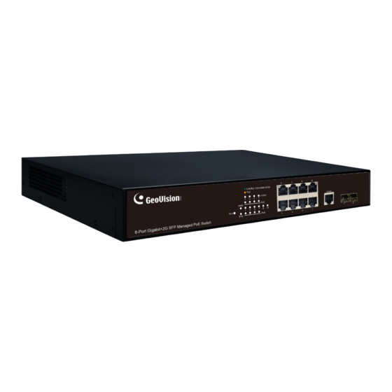
GV-APOE0811
PoE Switch
Packing List
1. GV-APOE0811 x 1
2. Power Cord x 1
3. Screw x 8
4. Rack Mount Kit
5. Rubber Feet x 4
Note: If any of these items is found missing or damaged, please contact your local supplier
for replacement.
Front Panel
March 8, 2021
8-Port Gigabit 802.3at Web Management
LED
Reset
Display
Button
6. GV-TA (1000Base-T Copper RJ-45 SFP
Transceiver) x 1
Gigabit
RJ-45
Functional
1
Gigabit
Not
SFP
Advertisement
Table of Contents

Related Manuals for GeoVision GV-APOE0811


Summary of Contents for GeoVision GV-APOE0811
- Page 1 GV-APOE0811 8-Port Gigabit 802.3at Web Management PoE Switch Packing List 1. GV-APOE0811 x 1 6. GV-TA (1000Base-T Copper RJ-45 SFP 2. Power Cord x 1 Transceiver) x 1 3. Screw x 8 4. Rack Mount Kit 5. Rubber Feet x 4 Note: If any of these items is found missing or damaged, please contact your local supplier for replacement.
- Page 2 LED Indicators on the switch Color/Status Description Green System powered on. Blinking Green System is working. Network through the corresponding port has been successfully established at 10/100 Mbps. Network through the corresponding port has been Link/Act Green successfully established at 1000 Mbps. Data currently being sent through the corresponding port Blinking Red / Green at 10/100 (orange) or 1000 (green) Mbps.
- Page 3 Mount Installation Desktop Rack March 8, 2021...
- Page 4 Connecting to GV-IP Cameras / Systems / Switches GV-APOE0811 can be connected to up to 8 GV-IP Cameras and 2 GV-NVR / DVR / VMS Systems or switches. You can also extend the connections by connecting to other switches. Note: The maximum cable length for: •...
- Page 5 Accessing Web Interface Users can log in the Web interface to manage and set up the switch. Follow the below steps to log in the Web interface. 1. To access the Web user interface, type the default IP 192.168.0.250 into your Web browser.
- Page 6 Web Interface 1. Management > Configuration > Save Configuration. 2. Click Restore Factory Default to restore the switch to the original configuration. Note: After loading default by pressing the Reset button or from the Web interface, you will need to configure IP address and Password again. Updating Firmware 1.
Need help?
Do you have a question about the GV-APOE0811 and is the answer not in the manual?
Questions and answers