
Related Manuals for Effekta TRITON M3


Summary of Contents for Effekta TRITON M3
- Page 1 Uninterruptible Power Supply TRITON M3, 100 200 kVA Operating Manual V 1.0 Article Numbers: ACX33TRS100Kxxxx ACX33TRS120Kxxxx ACX33TRS160Kxxxx ACX33TRS200Kxxxx...
-
Page 2: Table Of Contents
Contents 1.Safety ................................2 1.1 Safety notes ............................2 1.2 Symbols used in this guide ......................2 2.Main Features ............................. 3 2.1 Summarization ........................... 3 2.2 Functions and Features ........................3 3.Installation ..............................4 3.1 Unpack checking..........................4 3.2 The appearance of the product ..................... 4 3.3 LCD control panel ........................... -
Page 3: 1.Safety
1.Safety Important safety instructions – Save these instructions There exists dangerous voltage and high temperature inside the UPS. During the installation, operation and maintenance, please abide the local safety instructions and relative laws, otherwise it will result in personnel injury or equipment damage. Safety instructions in this manual act as a supplementary for the local safety instructions. -
Page 4: 2.Main Features
2.Main Features 2.1 Summarization This series UPS is a kind of three-in-three-out high frequency online UPS, it provides seven specifications: The 100~200kVA. The UPS can solve most of the power supply problems, such as blackout, over-voltage, under-voltage, voltage sudden drop, oscillating of decreasing extent, high voltage pulse, voltage fluctuation, surge, inrush current, harmonic distortion (THD), noise interference, frequency fluctuation, etc.. -
Page 5: 3.Installation
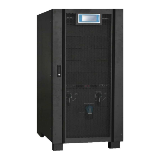
3.Installation 3.1 Unpack checking 1. Don’t lean the UPS when moving it out from the packaging 2. Check the appearance to see if the UPS is damaged or not during the transportation, do not switch on the UPS if any damage found. Please contact the dealer right away. 3. - Page 6 HIP33100-33120 Front View(internal) Rear View(internal)...
- Page 7 HIP33160 Front View(internal) Rear View(internal)...
- Page 8 HIP33200 Front View(internal) Rear View(internal) (1) LCD panel : LCD and LED display (2) Front lock (3) Lightning arrester cover plate : Remove cover plate to replace lightning arrester (4) Bypass switch cover plate : Remove cover to operate bypass switch (5) Dustproof net plate (6) Fuse Box : Input fuses and Battery fuses inbuilt, box 1 connected to module 1 (7) Communication panel...
- Page 9 (14) Parallel port 1/2 (15) The input filter capacitor switch : connect capacitor or not (16) Bypass Switch (17) Update RS485 port : use to update UPS software (18) LBS port Communication panel: (1) Communication panel fixed screw (2) Intelligent slot 1 : insert SNMP card or Dry contact card (3) Intelligent slot 2 : insert SNMP card or Dry contact card (4) RS485 port 1/2 (5) BAT_T port 1/2 : connect battery temperature sensor box...
- Page 10 1-6:Dustproof net plate fixed screw...
-
Page 11: Lcd Control Panel
3.3 LCD control panel LCD control panel introduction (1)LED(from top to bottom: “mains output”, “bypass output”、“battery output”、“alarm”) (2)LCD display (3)Founction button 3.4 Installation notes Note: Consider for the convenience of operation and maintenance, the space in front and back of the cabinet should be left at least 100cm and 80cm respectively when installing the cabinet. -
Page 12: External Protective Devices
◆The highest altitude that UPS may work normally with full load is 1500 meters. The load capacity should be reduced when this UPS is installed in place whose altitude is higher than 1500 meters, shown as the following table: (Load coefficient equals max load in high altitude place divided by nominal power of the UPS)... -
Page 13: Power Cable Connect
Cable Dimension AC Input AC Output DC Input Grounding cabinet CAUTION! Protective earth cable: Connect each cabinet to the main ground system. For Grounding connection, follow the shortest route possible。 WARNING! FAILURE TO FOLLOW ADEQUATE EARTHING PROCEDURES MAY RESULT IN ELECTROMAGNETIC INTERFERENCE OR IN HAZARDS INVOLVING ELECTRIC SHOCK AND FIRE 3.7 Power cable connect Once the equipment has been finally positioned and secured, connect the power cables as... -
Page 14: Battery Connection
WARNING! If the load equipment is not ready to accept power on the arrival of the commissioning engineer then ensure that the system output cables are safely isolated at their ends Connect the safety earth and any necessary bonding earth cables to the copper earth screw located on the floor of the equipment below the power connections. -
Page 15: Ups Multi-Module Installation
Note: The BAT+ of the UPS connect poles is connected to the anode of the positive battery, the BAT-N is connected to the cathode of the positive battery and the anode of the negative battery, the BAT- is connected to the cathode of the negative battery。 Factory setting of the long-run unit is battery quantity---32pcs, battery capacity---12V65AH. -
Page 16: Lbs Installation
Make sure each UPS input breaker is in “off” position and there is no any output from each UPS connected. Battery groups can be connected separately or in parallel, which means the system itself provides both separate battery and common battery. WARNING! Make sure the N、... - Page 17 3.10.1 LCD setting Set every UPS of the systems to be LBS Master or LBS Slave. For instance if the UPS belongs to LBS master system, its LBS setting must be set to Master. 3.10.2 LBS cable installation The two ports of one mesh wire should be plug into RJ45 interface of any one UPS of both master and slave system.
-
Page 18: 4.Operation
4.Operation 4.1 Operation Modes The UPS is a double-conversion on-line UPS that may operate in the following alternative modes: ◆Normal mode The rectifier/charger derives power from the AC Mains and supplies DC power to the inverter while floating and boosting charge the battery simultaneously. Then, the inverter converts the DC power to AC and supplies to the load. -
Page 19: Turn On/Off Ups
A manual bypass switch is available to ensure continuity of supply to the critical load when the UPS is out of order or in repair and this manual bypass switch bears for equivalent rated load. 4.2 Turn on/off UPS 4.2.1 Restart procedure CAUTION! MAKE SURE GROUNDING IS PROPERLY DONE! ◆... - Page 20 should feed the inverter without interruption. At this time, the LEDs of battery should be turned on. ◆ Switch on the MAINS to simulate utility recovery, the rectifier will restart automatically after 20 seconds and the inverter will supply to the load. It is suggested to use Dummy loads for testing.
- Page 21 ◆ Switch ON the output breaker. ◆ Switch ON the input breaker. The UPS powers from the static bypass instead of the maintenance bypass, then the bypass LED will light up. ◆ Switch OFF the maintenance bypass breaker, then the output is supplied by the bypass of the modules.
-
Page 22: The Display
UPS area, so a label should be posted to advise service personnel that the UPS circuit is under maintenance。 WARNING! Wait for about 5 minutes for the internal D.C. bus bar capacitors to be completely discharged 4.3 The Display 4.3.1 LCD display Introduction CAUTION! The display provides more functions than those described in this manual... - Page 23 TURN TO BYPASS CONFIRM TURN TO BYPASS BYPASS MODE TURNING OFF SELFTEST SELFTEST----UPS TESTING INQUIRE INQUIRE---- DETAIL INQUIRE---- OUTPUT INQUIRE---- INPUT...
- Page 24 INQUIRE----BATTERY INQUIRE----LOAD INQUIRE ----ALARM OFF INQUIRE ----ALARM ON INQUIRE----SERVICE USER SETUP PASSWORD USER SETUP TIME SET USER KEY SET LANGUAGE SET Alarm Information...
- Page 25 Event log UPS Alarm Warning Buzzer Rectifier Fault Beep continuously Fault LED lit Inverter fault(Including Inverter Beep continuously Fault LED lit bridge is shorted) Inverter Thyristor short Beep continuously Fault LED lit Inverter Thyristor broken Beep continuously Fault LED lit Bypass Thyristor short Beep continuously Fault LED lit...
-
Page 26: Options
Overload Once per second blinking No battery Once per second Battery LED blinking Battery under voltage Once per second Battery LED blinking Battery low pre-warning Once per second Battery LED blinking Internal Communication Error Once per second Fault LED blinking DC component over limit. -
Page 27: Appendix 1 Specifications
Appendix 1 Specifications Model 100kVA 120kVA 160kVA 200kVA Capacity 90kW 108kW 144kW 180kW Phase 3 Phase 4 Wires and Ground Rated Voltage 380/400/415Vac Voltage Range 208~478Vac Frequency Range 40Hz-70Hz ≥0.99 Power Factor Input ≤3%(100% nonlinear load) Current THDi Max.voltage:220V:+25%( optional +10%,+15%,+20%); 230V:+20%( optional +10%,+15%);... - Page 28 Battery (50/60±0.1)Hz Mode Crest Factor ≤2% with linear load ≤5% with non linear load ±192V/±204V/±216V/±228V/±240VDC Voltage (32 /34/36/38/40PCS) Battery Charge Current(A) Transfer Time Utility to Battery : 0ms; Utility to bypass: 0ms Load≤110%: last 60min, ≤125%: last 10min, ≤150%: last AC Mode 1min, ≥150% change to bypass.
-
Page 29: Appendix 2 Problems And Solution
Appendix 2 Problems and Solution In case the UPS can not work normally, it might be wrong in installation, wiring or operation. Please check these aspects first. If all these aspects are checked without any problem, please consult with local agent right away and provide below information. (1)... - Page 30 The UPS does not indicate any failure, Output cable does not well Make sure the output cable is well but output do not connected connected. have voltage Module does well inserted; The UPS module Pull out the module and insert again; The left coronal screw is not can not transfer to Tighten the screw;...
-
Page 31: Appendix 3 Rs232 Communication Port Definition
Appendix 3 RS232 communication port definition Definition of Male port : Connection between PC RS232 port and UPS RS232 port PC RS232 port UPS RS232 port ,PC Pin 2 Pin 2 send receive ,UPS Pin 3 Pin 3 send receive Pin 5 Pin 5 ground... -
Page 32: Appendix 4 Usb Communication Port Definition
◆ Timing off/on setting。 RS-232 communication data format Baud rate ---------- 2400bps Byte length ---------- 8bit End bit ---------- 1bit Parity check ---------none CAUTION! USB & RS232 & RS485 ports cannot be used at the same time. Appendix 4 USB communication port definition Definition of USB port :... - Page 33 ◆ Timing off/on setting。 USB communication data format Baud rate ---------- 2400bps Byte length ---------- 8bit End bit ---------- 1bit Parity check ---------none CAUTION! USB & RS232 & RS485 ports cannot be used at the same time.
- Page 34 Appendix 5 RS485 communication port definition Definition of port : Connection between the Device’s RS485 port and UPS RS485 port. Description device(RJ45) UPS(RJ45) 485+ “A“ Pin 1/5 Pin 1/5 Pin 2/4 Pin 2/4 485 -“B” Available function of RS485 ◆ Monitor UPS power status。 ◆...
-
Page 35: Appendix 6 Lbs Communication Port Definition
Appendix 6 LBS communication port definition Definition of port : Connection between the UPS1’s LBS1 port and UPS2’s LBS2 port. Description UPS1 LBS1(RJ45) UPS2 LBS2(RJ45) Pin 1/5 Pin 1/5 LBS_BPSIDE_BC Pin 2/4 Pin 2/4 LBS_TRACE_BC Pin 8 Pin 8 Available function of LBS ◆The output power of two or more UPS in non-parallel system should be synchronized with each other. -
Page 36: Appendix 7 Bat_T Communication Port Definition
Appendix 7 BAT_T communication port definition Definition of port : Connection between the BAT_T box port and UPS2’s BAT_T port. (RC77002) Temperature sensor(RJ45) UPS2 BAT_T(RJ45) Description Pin 1/5 Pin 1/5 Pin 2/4 Pin 2/4 Pin 7 Pin 7 Pin 8 Pin 8 Connection between the BAT_T box port and UPS2’s BAT_T port. -
Page 37: Appendix 8 Drycontact Port Definition
Appendix 8 Drycontact port definition Definition of port : Drycontact Description Pin 1 Pin 2 DRY_GENER Pin 3 DRY_BP_O Pin 4 DRY_BP_S... -
Page 38: Appendix 9 Repo Instruction
Appendix 9 REPO instruction Definition of port : Connection diagram: Connection between the button and UPS REPO port. Button UPS REPO Description Pin 1 Pin 1 Pin 2 Pin 2 ◆In addition to the local EPO push button on the front panel of the UPS (that stops operation of that module when pressed for more than 3 second), the UPS also supports a remote emergency stop (REPO).
Need help?
Do you have a question about the TRITON M3 and is the answer not in the manual?
Questions and answers