Table of Contents
Advertisement
Quick Links
Advertisement
Table of Contents

Related Manuals for Effekta MKD 6 kVA RT


Summary of Contents for Effekta MKD 6 kVA RT
- Page 1 MKD 6 – 10 kVA RT (XL) Operating Manual V 1.2 Device: Article number: MKD 6 kVA RT ACX11MKT6K000000 MKD 6 kVA RT XL ACX11MKT6K000RXL MKD 10 kVA RT ACX11MKT10K00000 MKD 10 kVA RT XL ACX11MKT10K00RXL Translation of the original operating manual...
- Page 2 UPS: MKD 6-10 kVA RT Legal Notice Legal Notice by EFFEKTA Regeltechnik GmbH This documentation is solely intended for the operator and his staff. The content of this documentation (texts, figures, drawings, graphics, plans, etc.) may not be copied or distributed in part or in full without our written consent, nor can it be used without authorization for competitive purposes or given made accessible to third parties.
-
Page 3: Table Of Contents
UPS: MKD 6-10 kVA RT Table of Contents Table of Contents Introduction ......................5 Preface ........................5 Validity ........................6 Storage ........................6 Abbreviations, terms and symbols ................6 Information obligation ....................9 Warranty conditions ....................10 Limitation of Liability ....................11 Safety Instructions .................... - Page 4 UPS: MKD 6-10 kVA RT Table of Contents Initial operation of the UPS ................... 74 Messages, error codes and corrective actions ............ 76 Messages for specific operation modes: ..............76 Error messages on the UPS: ................... 76 Error messages in the parallel system: ..............79 Troubleshooting ....................
-
Page 5: Introduction
Please read this operating manual carefully and take note particular note of the safety instructions! If you have questions about the device, the technical supervisor at your company or our employees will gladly assist you. Your EFFEKTA Regeltechnik GmbH MKD Series... -
Page 6: Validity
(UPS) defined in the technical data as a whole or as it refers to modules, components and individual parts that were developed and built by EFFEKTA Regeltechnik GmbH ( Chapter 13. Technical data). Read this documentation carefully and familiarize yourself with the product before you begin operating it. - Page 7 UPS: MKD 6-10 kVA RT Introduction Text marked with WARNING! provides a warning about hazards. If accident prevention measures are not taken, these hazards may result in serious (irreversible) injuries or even death! Text marked with CAUTION! provides a warning about hazards. If accident prevention measures are not taken, these dangerous situations can lead to slight or medium reversible injuries.
- Page 8 UPS: MKD 6-10 kVA RT Introduction Warning about proper handling of accumulators! Warning about handling explosive materials! Instruction symbols: Take note of the provided documentation and/or instructions! Disconnect before working! Environmental symbols: Identifies instructions for recycling. Identifies components that are subject to the Electronic Scrap Regulation. Identifies components or parts that must be disposed of properly.
-
Page 9: Information Obligation
This applies, in particular, to maintenance, operating and cleaning personnel including persons responsible for transportation and/or disposal. EFFEKTA Regeltechnik GmbH is not liable for damage incurred or caused by staff who have not been trained or who have been insufficiently trained! -
Page 10: Warranty Conditions
UPS: MKD 6-10 kVA RT Introduction Warranty conditions The receipt of delivery is considered as the record for the initial purchase and should be kept in a safe place. It will be necessary for making use of the warranty. If the product is passed on to another user, this user has the right to the warranty for the remainder of the warranty period. -
Page 11: Limitation Of Liability
We are not liable for damage or consequential damage, whether directly, unintentionally or caused by negligence. EFFEKTA Regeltechnik GmbH does not provide either explicit or implicit warranties related to this device and its quality, performance, salability or suitability for a certain purpose. In some countries, the exclusion of implicit warranties is not permitted by law. -
Page 12: Safety Instructions
UPS: MKD 6-10 kVA RT Introduction or other claims, even if EFFEKTA Regeltechnik GmbH was informed about the possibility of such damage in advance. This exemption also includes any liability that can result from the claims of third parties against the initial purchaser. -
Page 13: Prevention Of Personal Injury / Property Damage
Observe the required steps. Only use original replacement parts from EFFEKTA Regeltechnik GmbH. Environmental protection Send the product back to EFFEKTA Regeltechnik GmbH after the end of its service life. We will ensure its environmentally friendly disposal. Transport and storage The UPS may only be transported to the intended location in the original pack- aging. -
Page 14: Positioning
Due to the possibility of existing energy storage (accumulators) within a UPS, devices must generally be inspected by EFFEKTA Regeltechnik GmbH or a qualified service center after transportation damages. In the case of transportation damages, there is a high risk that the energy storage units and/or their electrical connections have been affected. -
Page 15: Connection
UPS: MKD 6-10 kVA RT Safety Instructions Connection Always use the connection terminals or blocks provided for the purpose of connecting the UPS. To avoid electrical hazards, the connection of the unit must only be made under de-energized conditions. The PE (protective earth) conductor must be connected without fail. The UPS- device, as well as the connected loads, must not be used without the PE conductor under any circumstances! The UPS output is supplied with power even in the event of a power outage;... -
Page 16: Operation
UPS: MKD 6-10 kVA RT Safety Instructions Should an emergency power-off circuit “EPO” or “REPO” (REMOTE EMERGENCY POWER OFF) be installed, this control circuit must unconditionally be separated from all other electrical circuits by reinforced insulation. The purpose of an EPO connection is for emergency power off and the release of the loads. -
Page 17: Maintanence, Service And Malfunctions
UPS: MKD 6-10 kVA RT Safety Instructions Never dispose of accumulators with regular household waste! Local disposal regulations must be observed! 2.10 Maintanence, service and malfunctions Attention – risk of electric shock. Even after switching off the supply with the power button or after disconnecting the accumulator feed, parts of the UPS can still carry high voltages. -
Page 18: Ups Device Description
UPS: MKD 6-10 kVA RT UPS Device Description UPS device description This UPS device is an ONLINE UPS after the double conversion principle. Based on the outstanding performance according to EN 62040-3, the UPS receives “Class 1” (VFI-SS-111) classification. This way subsequently connected appliances will be optimally provided for, irrespective of how a primary source of power (mains power supply) performs. - Page 19 UPS: MKD 6-10 kVA RT UPS Device Description Standard operation mode (INVERTER MODE) The standard operation mode is characterized here by a classic double conversion. The supply network is converted to the DC intermediate circuit which then feeds the UPS output through an inverter (DC/AC converter). The by-pass is inactive here.
- Page 20 UPS: MKD 6-10 kVA RT UPS Device Description Fig. 3-4 Operating mode: static by-pass. Never leave the UPS in the static by-pass mode, or the fault mode, for a long period of time. The loads will continue to be supplied yet without any support function from the UPS.
- Page 21 UPS: MKD 6-10 kVA RT UPS Device Description Converter mode (CVF MODE) In addition to the customary operating modes, the UPS can also be switched to the converter mode. In this, the UPS performance is functionally equivalent to the standard operating mode but the UPS output is not mapped to the power input.
-
Page 22: The Device Series, Format And Housing Sizes
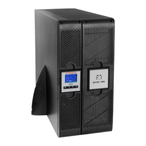
Description: Article number: Housing: Comment: [kVA] MKD 6 kVA RT 3 HE Standard ACX11MKT6K000000 External battery MKD 6 kVA RT XL 3 HE ACX11MKT6K000RXL bank MKD 10 kVA RT 5 HE Standard ACX11MKT6K000000 External battery MKD 10 kVA RT XL... - Page 23 UPS: MKD 6-10 kVA RT UPS Device Description Fig. 3-8 The MKD RT series can be used as a conventional RACK mounting unit (top) or as a TOWER standing unit (bottom). All devices can fundamentally be operated with an external battery bank whereby the entire capacity through the addition comes from the internal and external battery banks.
-
Page 24: The Device Components And Connection Areas
UPS: MKD 6-10 kVA RT UPS Device Description The device components and connection areas The MKD series is based on 19” rack housing. All device components for operation are arranged on the front of the device and those for the connection are on the back of the device. - Page 25 UPS: MKD 6-10 kVA RT UPS Device Description Fig. 3-12 Perspective view of the MKD 10 kVA series (Standard and XL Version). Fig. 3-13 View of the back side of the MKD 10 kVA series (Standard Version). Fig. 3-14 View of the back side of the MKD 10 kVA series (XL Version). MKD Series...
- Page 26 UPS: MKD 6-10 kVA RT UPS Device Description Front side: (A) Control panel for the UPS; (C) Detached front panel for the internal battery bank (10 kVA (B) Front panel of the UPS; version) Back side: ...
- Page 27 UPS: MKD 6-10 kVA RT UPS Device Description 3.3.1 Device label The following information can be found on the label for the UPS: the model name; the data for connection values; the article number; CE label; ...
- Page 28 UPS: MKD 6-10 kVA RT UPS Device Description Control panel keypad (1), (2), (3), (4) (Navigation): On/Off and start button (ON/OFF): The UPS can be switched on or off by activating the button. Also, the button facilitates starting and stopping the UPS. Up button (UP): By activating this button the parameters increase or the menu moves forward.
- Page 29 UPS: MKD 6-10 kVA RT UPS Device Description The standard page is not only generated by the UPS as output page when switching it on but, rather, the UPS also automatically returns to this page after longer pauses in input. The following presents the contents of the standard page in detail: Due to advancing improvements of the software, additional information could already exist that has not yet been addressed in detail here.
- Page 30 UPS: MKD 6-10 kVA RT UPS Device Description By-pass mode (BY-PASS MODE): The device is in by-pass mode, i.e. the UPS output (the load) is fed directly by the power supply. During this operation mode, the UPS scarcely carries out a protective or support function.
- Page 31 UPS: MKD 6-10 kVA RT UPS Device Description Overload mode (OVERLOAD MODE): The overload message belongs strictly to the warning messages. Depending on the current overload, the UPS will tolerate this overload for a short period. An acoustic signal is given during this operation mode (beep every second).
-
Page 32: Storage And Unpacking
UPS: MKD 6-10 kVA RT Storage and Unpacking Storage and unpacking Storage of the UPS If the UPS and/or the separate battery bank are to be stored after delivery, the following points must be observed: Always leave the UPS and the accessories in the original packaging; ... -
Page 33: Unpacking And Positioning The Ups
Pay attention to the following information (steps) when unpacking. Step 1: Open the outer box and remove the accessories and the padding surrounding it. Fig. 4-1 Accessories and padded parts of the MKD 6 kVA RT series. MKD Series... - Page 34 Step 2: Now lift the device out of the box and place it on a solid, flat base for further processing. Two persons should always lift the device together. The devices are equipped with accumulators and therefore too heavy for one person! Fig. 4-3 Removal process from the box, MKD 6 kVA RT series. MKD Series...
- Page 35 UPS: MKD 6-10 kVA RT Storage and Unpacking Use the handles on the box base when lifting a MKD 10 kVA device from the box. The handles are arranged on both sides here. Fig. 4-4 Removal process from the box, MKD 10 kVA RT series. When positioning the device, make sure it is standing securely with enough open space for further processing and installation.
-
Page 36: Installation And Connection Of The Ups
UPS: MKD 6-10 kVA RT Installation and Connection Installation and connection of the UPS All limit values listed in the technical data regarding the ambient and operation conditions are to be maintained in order to ensure the proper functioning of UPS. - Page 37 You can execute this procedure immediately on the UPS as well as one of the available external battery banks. Fig. 5-1 Front views with mounting bracket of the UPS devices MKD 6 kVA RT (A), MKD 10 kVA RT (B) and a corresponding external battery bank (C).
- Page 38 The detached front panel from the MKD 10 kVA and the external battery bank can be removed completely. Fig. 5-2 Front panel of the MKD 6 kVA RT, removed and set aside. Fig. 5-3 Detached front panel of the MKD 10 kVA RT. The same can be done with the external battery bank.
- Page 39 Step 4: Disengage the electrical connection to the battery bank (6 kVA) and remove the battery packs from the device. Again, place these on a secure base. Fig. 5-6 Removing the battery pack from the MKD 6 kVA RT. Fig. 5-7 Removing the battery packs from the MKD 10 kVA RT.
- Page 40 Also note that the external battery bank must always be installed under the UPS on account of the waste heat from the UPS. Fig. 5-9 Open representation of the guide rails on the MKD 6 kVA RT. MKD Series...
- Page 41 UPS: MKD 6-10 kVA RT Installation and Connection Fig. 5-10 Integration of the UPS or an external battery bank in the 19” cabinet, in this example of the MKD 10 kVA RT. Step 2 (only for MKD 10 kVA): Mount the safety brackets in the back on the connection box (rear side of the device) according to the following illustration.
-
Page 42: Installation As Standing Device (Tower)
UPS: MKD 6-10 kVA RT Installation and Connection Fig. 5-12 Securing all devices on the mounting bracket. Step 4: Equip the UPS (and the external battery bank) with the previously removed battery packs, contact these and reattach the safety covers and he front panels. - Page 43 UPS: MKD 6-10 kVA RT Installation and Connection – Make sure that the ventilation of the device is safeguarded. Because this UPS will be aired lengthwise, a minimum distance of 150 mm from adjacent equipment or walls in accordance with the airflow must be maintained;...
- Page 44 UPS: MKD 6-10 kVA RT Installation and Connection Step 3: To maintain the usual readability and ease of operation, turn the control panel 90°. Proceed according to the following figure. Fig. 5-15 Turning the control panel in compliance with the installation. Carefully remove the control panel from the front panel.
-
Page 45: Preparations For Connection
UPS: MKD 6-10 kVA RT Installation and Connection Preparations for connection The following ambient conditions and sanctions must be considered before the device can be connected. 5.3.1 Input protection for the UPS It is generally guarunteed that the UPS device is connceted to a suitable power supply network according to EN 62040. - Page 46 UPS: MKD 6-10 kVA RT Installation and Connection Fig. 5-16 Standard connection for the UPS with internally applied bridge for by- pass support (factory configuration). The circuit breaker (F1), for the input side fuse of the UPS, is to be selected in the “C”...
- Page 47 UPS: MKD 6-10 kVA RT Installation and Connection Fig. 5-17 “Increased safety” configuration of the UPS. Before connecting the by-pass feed, the internal supply bridge between the UPS input and the UPS by-pass must be removed. These are always assembled during the delivery state! In case of doubt, contact our service to receive current instructions or information concerning this.
- Page 48 Please find connection details in the respective operating manual (External By- pass). Further information can also be found here in chapter 15.3 External by-pass or from our Sales and Service Departments at EFFEKTA Regeltechnik GmbH. MKD Series...
- Page 49 UPS: MKD 6-10 kVA RT Installation and Connection 5.3.5 Output and load protection The operator is responsible for the general protection of the loads connected to the UPS output network. Therefore, we strongly recommend installing a residual current protective device (FI, RCD) and a circuit breaker before each load if required according to DIN VDE 0100-410 to guarantee full protection of persons and loads (see Fig.
- Page 50 Always make sure that the UPS and the battery bank are compatible. A corresponding product is inspected by EFFEKTA Regeltechnik GmbH and listed in 14 Scope of delivery / Accessories. MKD Series...
-
Page 51: Connecting The Ups Device
Contact our customer service about the necessary steps and procedures for this. Only EFFEKTA Regeltechnik GmbH service personnel is allowed to connect several UPS in parallel. This task requires substantial hardware, installation and parameter changes. - Page 52 Installation and Connection Fig. 5-20 Connection box with internal main terminal, MKD 6 kVA RT. Fig. 5-21 Connection box with internal main terminal, MKD 10 kVA RT. The connection of all AC wiring occurs under the pictured strain relief panel: the mains power supply, by-pass feed and load feed, as follows: Fig.
- Page 53 UPS: MKD 6-10 kVA RT Installation and Connection Fig. 5-23 “Increased safety” configuration of the UPS device. Fig. 5-24 „Converter mode“ configuration of the UPS. Mind that a by-pass feed does not exist within the converter mode (as well as no factory, internal by-pass bridge).
- Page 54 UPS: MKD 6-10 kVA RT Installation and Connection Fig. 5-25 Model representation of the power cord output on the UPS. It is implicit to connect the protective conductor here and to maintain the loop resistance all the way to the last load. It is likewise possible to secure the loads separately against over and fault currents and to directly ground them.
- Page 55 MKD devices (PLUG AND PLAY). Follow the preceding description for this. External battery bank connection, MKD 6 kVA RT (XL) In general, the battery bank connection can be executed on the front side of the device with the 6 kVA device: Step 1: Remove the front panel of both devices (UPS and battery bank);...
- Page 56 Installation and Connection Fig. 5-27 Closed coupling with a MKD 6 kVA RT XL USV (above). External battery bank connection MKD 10 kVA RT (XL) In contrast to the 6 kVA device, the battery bank connection on the 10 kVA USV...
- Page 57 UPS: MKD 6-10 kVA RT Installation and Connection 5.4.3 Connection for emergency shutdown, disconnection of the loads The function of the emergency shutdown EPO or REPO (REMOTE EMERGENCY POWER OFF) serves to immediately disconnect the connected loads from a distance of known dimensions. An external emergency power off button must be connected (potential-free contact) to the signal input REPO for this purpose.
- Page 58 UPS: MKD 6-10 kVA RT Installation and Connection Battery bank voltage low output (OPEN Pin 1 COLLECTOR against signal GND) Pin 2 Tx-UPS; Signal output Pin 3 Rx-UPS, Signal input Pin 5 Signal GND Network failure, output Pin 8 (OPEN COLLECTOR against signal GND) Pin 9 12 V for Signal GND...
- Page 59 UPS: MKD 6-10 kVA RT Installation and Connection 5.4.6 Connecting the SNMP adapter The SNMP adapter can likewise easily be slid into the adapter slot (INTELLIGENT SLOT) of the UPS and only needs to be connected with the network via a network cable (patch cable, category 5e or better). Further information for connection configuration is found in the respective adapter manual.
-
Page 60: Operation Of Device And Service
UPS: MKD 6-10 kVA RT Operation and Service Operation of device and service Due to the comprehensive protective functions which the device performs regarding the loads, the UPS runs completely automatically. This reduces the operation of the device to a few steps and this as well in the boundary of the power. - Page 61 UPS: MKD 6-10 kVA RT Operation and Service 6.1.1 Switching on and starting the UPS device with the mains power supply Starting the UPS device ensues through the following procedure. Observe the indicated sequence for this: The precondition is that a mains power supply does not exist. Switch the mains power supply on (circuit breaker).
- Page 62 UPS: MKD 6-10 kVA RT Operation and Service First, switch off all loads one at a time to ensure that these are switched off in a controlled manner; Now stop the UPS by pressing the On/Off button (1) for longer than 3 s.
- Page 63 UPS: MKD 6-10 kVA RT Operation and Service A switch to the autonomous mode is often intentionally applied to determine the autonomous period (support time) of the UPS device. 6.1.4 Direct switching on/off in the autonomous mode (COLD START) Also when there is not a mains power supply, the UPS device can be directly switched on in the autonomous mode.
-
Page 64: Menu Navigation, Settings And Commands
UPS: MKD 6-10 kVA RT Operation and Service Menu navigation, settings and commands In general, all settings are carried out, alarm data (LOGGING) and status data obtained and operation commands for the UPS executed via the UPS control panel. The following submenus are available in the main menu: Fig. - Page 65 UPS: MKD 6-10 kVA RT Operation and Service The arrow keys (2) , (3) can aid in navigating the menu accordingly whereby the page or parameter selection occurs by pressing the ENTER button By briefly pressing the arrow keys (< 1 s) during the standard mode, the status pages can be directly observed without navigating in the submenu via the main menu.
- Page 66 UPS: MKD 6-10 kVA RT Operation and Service Fig. 6-2 Model navigation in the “EVENT LOG” submenu. A complete list of the messages represented can be seen in chapter 8 Messages, error codes and corrective actions. 6.2.3 UPS monitor ) on the “MEASUREMENTS”...
- Page 67 UPS: MKD 6-10 kVA RT Operation and Service Fig. 6-3 Model navigation in the “MEASUREMENTS” submenu. 6.2.4 UPS control center ) on the “CONTROL” submenu, you arrive in By pressing the ENTER button ( the UPS control center. Here tasks can be initiated or basic settings carried out. These include: ...
- Page 68 UPS: MKD 6-10 kVA RT Operation and Service Resetting the error status: In the event, a correlated alarm or error arises in the UPS, the device pauses in error status until the error has been eradicated and the error status reset. Then the UPS switches again to the bypass made and can be started again.
- Page 69 UPS: MKD 6-10 kVA RT Operation and Service 6.2.5 UPS identification ) on the “IDENTIFICATION” submenu, you By pressing the ENTER button ( arrive at UPS identification. Data about the type of UPS, the device serial number and the current firmware (device software) is listed here. By pressing the up button ( >...
- Page 70 UPS: MKD 6-10 kVA RT Operation and Service MKD Series...
- Page 71 UPS: MKD 6-10 kVA RT Operation and Service Fig. 6-6 Model navigation in the “SETTINGS” submenu. Most settings can be and are permitted to be performed only when the device is in standby mode. Navigate to the desired menu page (parameter) here only with the arrow keys ( ) as well.
- Page 72 UPS: MKD 6-10 kVA RT Operation and Service Possible settings and ranges of the different parameters Parameter Setting options / Default (Display) Value ranges User password disable [<enable><disable>] If <enable> is set, a password must also be entered. Audio alarm enable [<enable><disable>] If <disable>...
- Page 73 UPS: MKD 6-10 kVA RT Operation and Service Parameter Setting options / Default (Display) Value ranges If <enable> is set, the UPS switches directly to the by- pass mode after being switched on. If <disable> is set, The UPS does not switch to the by- pass mode after being switched on but switches to the by-pass mode when an error or overload occurs.
- Page 74 UPS: MKD 6-10 kVA RT Operation and Service 6.2.7 Alarm mode of the UPS The UPS switches the output off provided the UPS switches to the error mode due to an internal problem. The loads will no longer be supplied; the display pictured here appears (for example).
-
Page 75: Initial Operation Of The Ups
UPS: MKD 6-10 kVA RT Initial Operation Initial operation of the UPS The initial operation generally requires that all previous chapters of this manual have already been successfully read or processed. Additionally, check that all connected loads are switched off. The initial operation of UPS devices is exclusively reserved for accredited personnel. - Page 76 UPS: MKD 6-10 kVA RT Initial Operation In the event that errors occur during the initial operation, these must first be analyzed and removed before the initial operation can be continued. MKD Series...
-
Page 77: Messages, Error Codes And Corrective Actions
UPS: MKD 6-10 kVA RT Error Messages Messages, error codes and corrective actions The following table contain the possible alarm, warning or status messages and their code numbers (ALARM CODES). The messages can be called up either on the standard display or on the “event ... - Page 78 UPS: MKD 6-10 kVA RT Error Messages Switch the UPS off, supply the The static by-pass is Feedback mode, loads from the manual or defective (energetic Alarm code: 93 external by-pass; report this to recovery system). customer service. The battery bank voltage is Battery bank connection very low, the battery bank Check the battery bank, its...
- Page 79 UPS: MKD 6-10 kVA RT Error Messages Alarm/Status Procedure/Corrective Reason: action: CODES The UPS detects an Switch the UPS off in a Intermediate circuit intermediate circuit with controlled manner or activate overvoltage (DC), voltage that is too high and the manual / external by-pass. Alarm code: 21 immediately switches to Report this to the customer...
-
Page 80: Error Messages In The Parallel System
UPS: MKD 6-10 kVA RT Error Messages The UPS detects an overvoltage in the battery Battery bank bank and switches the Report this to the customer overvoltage, charging unit off until the service. Alarm code: 16 battery bank voltage is within the operation limits again. -
Page 81: Troubleshooting
0049 / (0) 741 – 17451-52 Phone: 0049 / (0) 741 – 17451-29 Fax: You can also reach us via email at: kundendienst@effekta.com In addition, you can contact the relevant department or branch office directly as listed on our website: http://www.effekta.com MKD Series... -
Page 82: Software
UPS: MKD 6-10 kVA RT Software Software The UPS management software runs as a client / server application for heterogeneous networks or on a local computer. It works on any common platform (Win, Linux, UNIX). Remote access to the UPS and its data is possible and recordable. The software shows all relevant UPS data such as the accumulator condition, temperature, condition of the mains power supply, etc. -
Page 83: Maintenance And Service
UPS: MKD 6-10 kVA RT Maintenance and Service Maintenance and Service You can expect a long service life and interference-free operation from this product. The service life and reliability of the UPS is greatly dependent on the conditions of its environment. The ambient temperature and humidity in the vicinity of the device must remain within the specified range. - Page 84 UPS: MKD 6-10 kVA RT Maintenance and Service If the support time is not measured due to local conditions or regulations, we recommend the prophylactic replacement of the accumulators every other year to avoid any risk of an insufficient autonomous period (support time) caused by degenerated accumulators.
-
Page 85: Replacing Components / Accumulators
12.2 Replacing components / accumulators Replacing the accumulators and other UPS components must only be performed by personnel from EFFEKTA Regeltechnik GmbH or an accredited service center. During the replacement of the accumulators and other UPS components, the loads are directly connected to the mains power supply via an external by-pass whereby a support function cannot occur at this time. -
Page 86: Service Log
UPS: MKD 6-10 kVA RT Maintenance and Service Proper disposal of defective or degenerate components. Environmentally sound disposal of accumulators. Please contact our service hotline listed above for a complete list of our services or send us an email request. 12.4 Service log Please always enter all maintenance and service work performed on the UPS... - Page 87 UPS: MKD 6-10 kVA RT Maintenance and Service Date Tasks performed Performed by MKD Series...
-
Page 88: Technical Data
UPS: MKD 6-10 kVA RT Technical Data Technical data MKD 6 kVA RT (XL) MKD 10 kVA RT (XL) Model: 5.4 kW 9 kW Network 1 Phase, neutral conductor and PE conductor Nominal voltage 208 / 220 / 230 / 240 VAC... - Page 89 UPS: MKD 6-10 kVA RT Technical Data MKD 6 kVA RT (XL) MKD 10 kVA RT (XL) Model: 5.4 kW 9 kW Device class (XL) C2 (C2) C2 (C3) Communication Intelligent adapter slot (for AS400, SNMP) Safety: EN 62040-1 EMV:...
-
Page 90: Scope Of Delivery / Accessories
Description: Article No. MKD series, according to your order: MKD 6 kVA RT, MKD 10 kVA RT; MKD 6 kVA RT XL, MKD 10 kVA RT XL Base for the MKD series (6- Mounting 10 kVA), material, Mounting bracket as per... -
Page 91: Optional Accessories
UPS: MKD 6-10 kVA RT Accessories Optional accessories The components, devices and/or equipment listed below are accessories that fit the MKD series and that have been tested and approved by EFFEKTA Regeltechnik GmbH. 15.1 Communications adapter: Relay card (AS400) The relay card also belongs to the intelligent extension card and is used for the direct and potential-free contact with external controls and/or machines. -
Page 92: Communication Adapter: Snmp
UPS: MKD 6-10 kVA RT Accessories card is also configurable so that the configuration and switching performance can essentially be defined. Details about the card and the connection can be found in the operating manual for the relay card. 15.2 Communication adapter: SNMP The SNMP adapter integrates the UPS into a network and communicates via TCP/IP, Telnet or FTP. -
Page 93: External Battery Bank
The following battery banks are available as standard units: UPS: MKD 6 kVA RT XL MKD 10 kVA RT XL Article number ABC6X115009XX30E... - Page 94 UPS: MKD 6-10 kVA RT Accessories These battery banks (same type) can be switched on parallel without difficulty to, in turn, meet the requirements (load, autonomous time). Please contact our sales and service center to develop a suitable accumulator bank concept for your needs. Always keep in mind that, for connecting the UPS to an external battery bank, only the MKD XL Variant is suitable because this device commands a powerful charging unit.
-
Page 95: Wear Parts
All units labeled with a CE sign fulfill the EU harmonized standards and regulations. The EU-declaration of conformity for this product is available upon request. Please contact our 10 Service hotline. You can also find the declaration of conformity for this product on our website: http://www.effekta.com MKD Series... - Page 96 UPS: MKD 6-10 kVA RT Conformity EFFEKTA Regeltechnik GmbH Rheinwaldstraße 34 D – 78628 Rottweil MKD Series...
Need help?
Do you have a question about the MKD 6 kVA RT and is the answer not in the manual?
Questions and answers