Table of Contents
Advertisement
Quick Links
Advertisement
Table of Contents

Related Manuals for Eaton US-S ESF30 Series


Summary of Contents for Eaton US-S ESF30 Series
- Page 1 Mounting and Operating Instructions US-S ESF30 Mounting and Operating Instructions Fire-Resistant Cabinet Type US-S ESF30 Target group: qualified electricians according to DIN VDE 0105 Part 1 Target group. part 2: Electrical instucted persons...
-
Page 2: Table Of Contents
Content Content 5 Transport . . . . . . . . . . . . . . . . . . . . . . . . . . . . . 10 1 Important information . -
Page 3: Important Information
1 Important information 1 Important information ATTENTION! 1.1 General Calls attention to hazards that can cause damage to equip- Mounting work must always be performed by qualified ment or plant components, or can result in environmental electricians (also refer to DIN VDE 0105 Part 1, the German damage. -
Page 4: Copyright
2 Safety ised in consultation with CEAG. The approval / warranty is 2 Safety otherwise null and void. • The installation contractor shall supply the warranty for At the time of its development and production, the device the assembly work. was manufactured in accordance with the recognised techni- •... -
Page 5: Changes And Alterations To The Equipment
2 Safety instructions before commencing work on the equipment. been trained in possible hazards that may occur. A qualified This also applies if the person concerned has worked with person is anyone who, based on his/her training, expertise the same or similar equipment in the past or was trained by and experience as well as his/her knowledge of the relevant the manufacturer. -
Page 6: Layout
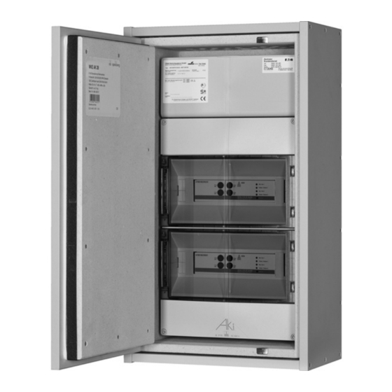
4 Layout 4 Layout 4.1.2 Dimensioned drawings US-S ESF30 28-P 4.1 US-S ESF30 28-P 4.1.1 Components US-S ESF30 28-P 918 36,14 918 36,14 4.1.3 Detail drawings for ventilation equipment US-S ESF30 28-P Terminal block Thermostatic control / temperature exceeded Thermostatic control of internal temperature Control module CU CG-S Thermostatic control of... -
Page 7: S Esf30 13-P
4 Layout 4.2 US-S ESF30 13-P 4.2.2 Dimensioned drawings US-S ESF30 13-P 4.2.1 Components US-S ESF30 13-P Terminal block Thermostatic control / temperature exceeded Thermostatic control of internal temperature Control module CU CG-S Thermostatic control of DC module external temperature Circuit switch-overs SKU CG-S Web module... -
Page 8: S Esf30 Sou5
4 Layout 4.3 US-S ESF30 SOU5 4.4 US-S ESF30 SOU3 4.3.1 Components US-S ESF30 SOU5 4.4.1 Components US-S ESF30 SOU3 Enclosure Circuit modules SOU CG-S 2 x 4 A Enclosure Circuit modules SOU CG-S 2 x 4 A 4.3.2 Dimensioned drawings US-S ESF30 4.4.2 Dimensioned drawings US-S ESF30 SOU5 SOU3... -
Page 9: S Esf30 Sou2
4 Layout 4.5 US-S ESF30 SOU2 4.6 US-S ESF30 SOU1 4.5.1 Components US-S ESF30 SOU2 4.6.1 Components US-S ESF30 SOU1 Enclosure Circuit module SOU CG-S 2 x 4 A Enclosure Circuit modules SOU CG-S 2 x 4 A 4.5.2 Dimensioned drawings US-S ESF30 4.6.2 Dimensioned drawings US-S ESF30 SOU2 SOU1... -
Page 10: Transport
5 Transport 5 Transport ATTENTION! Any damage to the equipment must be immediately reported to us in writing! 5.1 Brief notes about important transport considerations The recipient is responsible for the receiving inspection The shipped product and its packaging must be promptly inspected for damage, completeness, and other anomalies. -
Page 11: Assembly/Installation Us-S Esf30 28-P Und 13-P
6 Assembly/installation US-S ESF30 28-P und 13-P 6.3 Instructions for unhinging the doors 6.6 EHL/ESL wall fixing The doors are unhinged by pushing the pins from the leafs. For safety reasons, the door panels should always be un- hinged by at least 2 persons. 6.4 Fixing the hanging brackets onto the rear of the enclosure •... -
Page 12: Switching The Door Swing Us-S Esf30
6 Assembly/installation US-S ESF30 28-P und 13-P 6.7 Switching the door swing 6.10 Delivered scope US-S ESF30 28-P and 13-P • Our products are shipped complete with everything nee- ded and appropriate for installation. • The fire protection enclosures are shipped as described ATTENTION: in the prospectus. -
Page 13: Cable Routing In The Distribution Cabinet
6 Assembly/installation US-S ESF30 28-P und 13-P 6.12 Cable routing in the distribution cabinet • Pre-drill the point where the cable is to be inserted accor- ding to the cable diameter. Observe internal insulation, mounting plates and fan! • Insert existing cables through the cable bulkhead of the housing. -
Page 14: Pedestal Installation
7 Dismantling of the fan unit 6.13 Pedestal installation Install the pedestal of the ES enclosure in a manner that locates the ventilation gap above the pedestal rail (Figure 6). 2. Disconnect and remove the temperature sensor. Loosen the cable connection at the contacts of the termi- nal block. -
Page 15: Ventilation Diagram
8 Ventilation diagram 8 Ventilation diagram ATTENTION! The black compriband is part of the ventilation system and ensures, among other things, that only the „fresh“ supply air comes from below at the lower/rear side. This band must not be removed. EXHAUST AIR SUPPLY AIR Schematic diagram of the ventilation... -
Page 16: Ventilation Unit: Technical Data
10 Ventilation unit: technical data 10 Ventilation unit: technical data Power supply 185…230…245V/AC Operating voltage 50Hz Electricity consumption 0.15A Power Speed 2850 min-1 Air flow 164m³/h Static pressure 8.64mmH2O Noise level 45 dB(A) Operating temperature -10…70°C Thermal fuse Protection level 77°C Smoke detector Light alarm... -
Page 17: Connection Plan
11 Connection plan 11 Connection plan WARNING 230V AC ATTENTION Dangerous Voltage. May cause death heavy body injuries Danger caused by electrical voltage and property damage. Disconnect all poles of the device before starting to dismantle or changing the composition. Follow the instructions of VDE 0100 for 230 V main supply. -
Page 18: Setup And Installation Us-S Esf30 Sou5
9 Setup and installation US-S ESF30 SOU5, SOU3, SOU2, SOU1 9 Setup and installation US-S ESF30 SOU5, SOU3, SOU2, SOU1 9.1 Wall-mounted installation The unit is mounted with the included anchor screws, rated Only the dowels or anchor screws described in the "General for concrete walls at strength class C20/25 to C50/60 or ma- construction code approval"... - Page 19 Notes Notes Mounting and Operating Instructions Fire-Resistant Cabinet Type US-S ESF30 40071860245 (B) February 2020 www.ceag.de...
- Page 20 The aim of Eaton is to provide a reliable, efficient and safe power supply where it is needed most. Eaton's experts have comprehensive in-depth specialist knowledge in the area of energy management in the most diverse of sectors and therefore they are able to provide customer-specific, inte- grated solutions to meet the most challenging demands of its customers.
Need help?
Do you have a question about the US-S ESF30 Series and is the answer not in the manual?
Questions and answers