
Related Manuals for Eaton MTL CROUSE-HINDS Series


Summary of Contents for Eaton MTL CROUSE-HINDS Series
- Page 1 Instruction manual November 2016 MTL fieldbus networks INM 937x-FB2-Px SS Rev 1 937x-FB2-Px-SS Fieldbus Barrier System 6-spur & 12-spur, Stainless Steel enclosures...
-
Page 2: Declaration Of Conformity
DECLARATION OF CONFORMITY A printed version of the Declaration of Conformity has been provided separately within the original shipment of goods. However, you can find a copy of the latest version at http://www.mtl-inst.com/certificates INM 937x-FB2-Px-SS Rev 1... -
Page 3: Table Of Contents
CONTENTS DECLARATION OF CONFORMITY . . . . . . . . . . . . . . . . . . . . . . . . . . . . . . . . . . . . . . . . . . . . . . . . . . . . . . II GENERAL SAFETY INFORMATION . -
Page 4: General Safety Information
No changes to any of the components that might impair their explosion protection are permitted. If any information provided here is not clear: Contact Eaton’s MTL product line or one of its representatives. CAUTION! These enclosures are supplied with the latest type of fieldbus barrier, the 9377-FB-R. -
Page 5: Overview
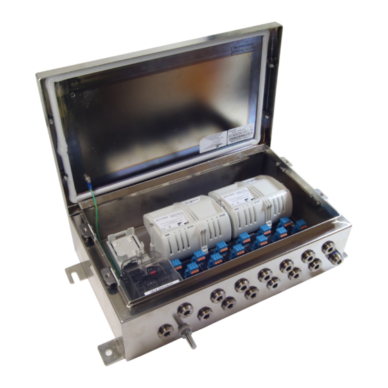
937x-FB2-Px-SS Fieldbus Barrier System 6-spur & 12-spur, Stainless Steel enclosures Figure 1 . 1 - Enclosure example showing model 9373-FB2-PC-SS Note: 9376-SP trunk surge protection module is optional and not supplied as standard OVERVIEW This manual explains the installation and maintenance procedures for the 937x-FB2-Px-SS Fieldbus Barrier range of enclosures and must be read in association with the product datasheets that contain the electrical data. -
Page 6: Description
DESCRIPTION The model numbers shown above comprise SS, increased safety, Ex e enclosures containing either one (9371 models) or two (9373 models) carrier-mounted 9377- FB-R fieldbus barrier modules. Each fieldbus barrier module converts a single, non- intrinsically safe fieldbus trunk into six intrinsically safe (IS) spur connections for connection to Foundation™... -
Page 7: Permitted Enclosure Combinations
Model type Nominal weight 9371-FB2-Px-SS 5.7 kg 9373-FB2-Px-SS 8.5 kg e) Adequate security should be provided against unauthorised interference. f ) All the necessary gland holes have been prepared in the enclosure. WARNING ! It is not permitted to create additional holes in the enclosure as this would violate the certification. - Page 8 138.5 9373-FB2 Fieldbus Barrier System, 12 Spur SS Enclosure TYP. 4 PLACES. TRUNK OUT SPUR 2 SPUR 4 SPUR 6 SPUR 8 SPUR 10 SPUR 12 TRUNK IN SPUR 5 SPUR 7 SPUR 9 SPUR 11 BREATHER SPUR 1 SPUR 3 Figure 3 .2 –...
- Page 9 Non- intrinsically safe trunk 9371-FB2 6-spur enclosure Host Control System 9377-FB-R Fieldbus Fieldbus Barrier module Power (6-spur) Supply Intrinsically safe spur Fieldbus instruments Non- intrinsically 9371-FB2 9371-FB2 safe trunk 6-spur enclosure 6-spur enclosure Host Control System 9377-FB-R 9377-FB-R Fieldbus Fieldbus Barrier module Fieldbus Barrier module Power (6-spur)
-
Page 10: 3 .3 Preparation
3 .3 Preparation a) Remove any temporary protection or packing materials. b) The enclosure can be mounted on any suitable structure using the enclosure’s integral mounting facilities. c) The fixing bolts must be suitable for the mounting surface and the environmental conditions. -
Page 11: Initial Electrical Installation
INITIAL ELECTRICAL INSTALLATION WARNING ! Before starting any electrical installation work, ensure that the incoming trunk connection is isolated from any source of power. CAUTION! The temperature inside the enclosure could rise to 75°C.Ensure that all cables and cable glands fitted are rated to withstand these temperatures. 4 .1 Preparation Loosen the captive screws of the enclosure lid and then remove it to obtain access... -
Page 12: Cable Shield Ground
Note: It is important to prevent this connection from loosening and also to protect it from corrosion. Where the trunk and spur cables are protected by steel wire armour, this should be treated as part of the “protective” ground. Normal practice is to bond the armour to the plant structure at both ends of each cable. -
Page 13: Trunk Shield Grounded At Host; Spur Cable Shields Grounded At Barrier
IMPORTANT NOTE 937x-FB2 enclosures are factory-supplied with Option 1 grounding. If power is applied locally, for example during commissioning, when the trunk cable shield is NOT providing a ground connection, the spur cable shields must (temporarily) be grounded according to Option 2. When the trunk cable shield ground has been fully instated (or restored), the grounding method should be returned to Option 1. - Page 14 F93-XE Grounding Fieldbus link terminator terminals Trunk (+) Trunk (-) terminals terminals Trunk screen Local terminals ground connection Image to be updated Figure 4 .3 – Trunk Terminal Area connector details Trunk cables pass through the enclosure wall via cable glands into the Trunk Terminal Area.
-
Page 15: Trunk Wiring
4 .3 .2 Trunk wiring Connect the trunk cable(s) in the following way. • Remove the cover that protects the Trunk Terminal Area by applying gentle pressure to the textured finger grips on each side of it: this releases the catches from the recesses in the carrier housing, so that the cover may be lifted away to reveal the trunk terminals. -
Page 16: Trunk Surge Module 9376-Sp
4 .5 Trunk Surge protection module 9376-SP The 9376-SP Trunk Surge protection module can be fitted to the TTA to prevent damage to the equipment from voltage and current surges that could occur on the trunk wiring. The 9376-SP is a four pin module that plugs into the upper end face of the Trunk Terminator Assembly. -
Page 17: Blanking Plugs
4 .7 Blanking Plugs . Blanking plugs of factory-supplied Fieldbus Barriers are lightly tightened for ease of removal. Any blanking plugs that are not removed from the fieldbus barrier must be tightened to the required torque to meet the IP rating. Two types of blanking plug are supplied with the Fieldbus Barrier as shown in figures 4.8 and 4.9 below and should be tightened to a torque rating as shown in the table below. -
Page 18: Maintenance
5 MAINTENANCE When the enclosure is installed in a hazardous area it is important for personnel to understand what activities are permissible when fieldbus power is present and what are not. WARNING ! Read and understand what work is permitted inside the enclosure. Failure to comply with these instructions can endanger the lives or health of personnel and risk damage to the plant and the environment. -
Page 19: Removing A Fieldbus Barrier Module (Refer To Figure 5 .1)
5 .2 .1 Removing a Fieldbus Barrier module (refer to Figure 5 .1) a) Loosen the three captive fixing screws (C & D) on the module to release it. The screws are all spring-loaded and should retract when the thread has disengaged. -
Page 20: Mounting A Module
5 .3 .1 .1 Mounting a module Refer to Figure 5.3. Orientate the module so that the smaller front clip is facing the trunk terminals, then: • push the module so that the safety retaining clip on the carrier housing fits into the loop on the module •... -
Page 21: Trunk Connections
a) Loosen the two screws securing the pluggable, spur-wiring connector to the carrier and unplug it. b) Plug the Spur Surge module into the vacant socket on the carrier and tighten the two fixing screws and its grounding screw, all to a recommended torque of 0.4 Nm. -
Page 22: Troubleshooting
TROUBLESHOOTING The Fieldbus Barriers inside the enclosure are fitted with LED indicators to assist the user in fault identification. Consult the following tables to understand the meaning of the LED states. Power LED (Green) Trunk power applied Insufficient or no trunk power CAUTION! THE POWER LED WILL NOT LIGHT UNTIL THE VOLTAGE AT THE BARRIER HAS RISEN TO A VALUE OF AT LEAST 15.7V, BUT COULD REMAIN LIT EVEN AFTER THE... -
Page 23: Atex Information
ATEX information The Essential Health and Safety Requirements (Annex II) of the EU Directive 2014/34/ EU [the ATEX Directive - safety of apparatus] requires that the installation manual of all equipment used in hazardous areas shall contain certain information. This annex is included to ensure that this requirement is met. -
Page 24: Inspection And Maintenance
Read also the Special Conditions for Safe Use (below) for any additional or more specific information. Special Conditions for Safe Use 1. The equipment shall only be powered from supplies conforming to IEC 61158 2. When a Trunk Surge Module is fitted, the power input circuit will not withstand a 500V a.c. - Page 25 Enclosure marking (Made in India) Module carrier Barrier marking Trunk surge protector marking Terminator marking INM 937x-FB2-Px-SS Rev 1...
- Page 26 THIS PAGE IS LEFT INTENTIONALLY BLANK INM 937x-FB2-Px-SS Rev 1...
- Page 27 THIS PAGE IS LEFT INTENTIONALLY BLANK INM 937x-FB2-Px-SS Rev 1...
- Page 28 MTL Instruments GmbH, Heinrich-Hertz-Str. 12, 50170 Kerpen, Germany UNITED ARAB EMIRATES Cooper Industries/Eaton Corporation Tel: +49 (0)22 73 98 12 - 0 Fax: +49 (0)22 73 98 12 - 2 00 Office 205/206, 2nd Floor SJ Towers, off. Old Airport Road, E-mail: csckerpen@eaton.com...
Need help?
Do you have a question about the MTL CROUSE-HINDS Series and is the answer not in the manual?
Questions and answers