Advertisement
Quick Links
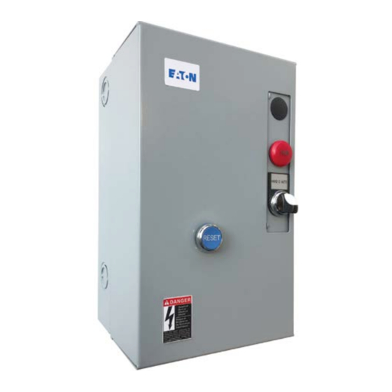
Instructions and Operation P52899
Box 1 and Box 2 non-combination enclosed
control and C600M cover control kit wiring
Contents
Description
General information . . . . . . . . . . . . . . . . . . . . . . . . . . . . . . . . . . . . . . . . . . . . . . . . . . . . . . . . . . . . . . . 2
Cover control installation . . . . . . . . . . . . . . . . . . . . . . . . . . . . . . . . . . . . . . . . . . . . . . . . . . . . . . . . . . . 2
Wiring diagrams . . . . . . . . . . . . . . . . . . . . . . . . . . . . . . . . . . . . . . . . . . . . . . . . . . . . . . . . . . . . . . . . . . 3
Box 1 starter/contactor mounting locations . . . . . . . . . . . . . . . . . . . . . . . . . . . . . . . . . . . . . . . . . . . . 14
Box 2 starter/contactor mounting locations . . . . . . . . . . . . . . . . . . . . . . . . . . . . . . . . . . . . . . . . . . . . 15
Enclosures . . . . . . . . . . . . . . . . . . . . . . . . . . . . . . . . . . . . . . . . . . . . . . . . . . . . . . . . . . . . . . . . . . . . . 16
Reset rods . . . . . . . . . . . . . . . . . . . . . . . . . . . . . . . . . . . . . . . . . . . . . . . . . . . . . . . . . . . . . . . . . . . . . 16
Reset rod installation . . . . . . . . . . . . . . . . . . . . . . . . . . . . . . . . . . . . . . . . . . . . . . . . . . . . . . . . . . . . . 17
Box 1
Effective July 2019
Supersedes May 2015
Box 2
Page
Advertisement

Related Manuals for Eaton Box 1


Summary of Contents for Eaton Box 1
-
Page 1: Table Of Contents
Effective July 2019 Instructions and Operation P52899 Supersedes May 2015 Box 1 and Box 2 non-combination enclosed control and C600M cover control kit wiring Contents Description Page General information . . . . . . . . . . . . . . . . . . . . . . . . . . . . . . . . . . . . . . . . . . . . . . . . . . . . . . . . . . . . . . . 2 Cover control installation . -
Page 2: General Information
Effective July 2019 General information Box 1 enclosure This publication is to be used for Eaton non-combination enclosures designed to accept the M22 series 22 mm cover control devices . If the enclosure catalog number already has cover control devices mounted, the existing reverse “c”... -
Page 3: Wiring Diagrams
Instructions and Operation P52899 Box 1 and Box 2 non-combination enclosed control and C600M cover control kit wiring Effective July 2019 Wiring diagrams Wiring diagrams: NEMA and IEC starters and contactor ® CONNECTIONS FOR NON-REVERSING STARTER CONNECTIONS FOR REVERSING STARTER "C2"... - Page 4 Instructions and Operation P52899 Box 1 and Box 2 non-combination enclosed control and C600M cover control kit wiring Effective July 2019 Wiring diagrams: Lighting—electrically held, CN35 CONNECTIONS FOR 2, 3, 4, 5, AND 6 POLE CONTACTOR CONFIGURATIONS CN35A 10 AMP...
- Page 5 Instructions and Operation P52899 Box 1 and Box 2 non-combination enclosed control and C600M cover control kit wiring Effective July 2019 Wiring diagrams: Lighting—mechanically held, C30CN CONNECTIONS FOR C30CN SERIES UPTO 12 POLE CONTACTOR CONFIGURATIONS "C2" C30CNM MECHANICALLY HELD 3/L2...
- Page 6 Box 1 and Box 2 non-combination enclosed control and C600M cover control kit wiring Effective July 2019 C600M wiring kit diagrams—Box 1 and Box 2 STOP/START OR OFF/ON OVAL. OPTIONS SHOWN: RUN LIGHT AND OFF LIGHT DASHED COMPONENTS ARE OPTIONAL...
- Page 7 Box 1 and Box 2 non-combination enclosed control and C600M cover control kit wiring Effective July 2019 C600M wiring kit diagrams—Box 1 and Box 2 HAND/OFF/AUTO OR TEST/OFF/AUTO 3-POSITION SELECTOR SWITCH OPTIONS SHOWN: RUN LIGHT, AND OFF LIGHT DASHED COMPONENTS ARE OPTIONAL...
- Page 8 Box 1 and Box 2 non-combination enclosed control and C600M cover control kit wiring Effective July 2019 C600M wiring kit diagrams—Box 1 and Box 2 REV/OFF/FWD OR DWN/OFF/UP 3-POSITION SELECTOR SWITCH OPTIONS SHOWN: REV/DWN LIGHT AND FWD/UP LIGHT DASHED COMPONENTS ARE OPTIONAL...
- Page 9 Box 1 and Box 2 non-combination enclosed control and C600M cover control kit wiring Effective July 2019 C600M wiring kit diagrams—Box 1 and Box 2 REV/FWD OR DWN/UP CUSTOMER CONTROL OPTIONS SHOWN: REV/DWN LIGHT AND FWD/UP LIGHT, OFF LIGHT DASHED COMPONENTS ARE OPTIONAL...
- Page 10 Instructions and Operation P52899 Box 1 and Box 2 non-combination enclosed control and C600M cover control kit wiring Effective July 2019 C600M wiring kit diagrams—Box 2 LIGHTING CONTACTOR C30CN_ ELECTRICALLY HELD. REF.: OFF/ON OVAL PUSHBUTTON RED RUN GRN OFF DASHED COMPONENTS ARE OPTIONAL...
- Page 11 Instructions and Operation P52899 Box 1 and Box 2 non-combination enclosed control and C600M cover control kit wiring Effective July 2019 C600M wiring kit diagrams—Box 2 LIGHTING CONTACTOR C30CN_ MECHANICALLY HELD 2-WIRE CONTROL. REF.: OFF/ON 2-POSITION SELECTOR SWITCH RED RUN GRN OFF REF:-COMBINATION OF COIL VOLTAGE(B) 240VAC TO CONTROL MODULE VOLTAGE 200-277V AC (H0) DASHED COMPONENTS ARE OPTIONAL.
- Page 12 Instructions and Operation P52899 Box 1 and Box 2 non-combination enclosed control and C600M cover control kit wiring Effective July 2019 C600M wiring kit diagrams—Box 2 LIGHTING CONTACTOR C30CN_ MECHANICALLY HELD 2-WIRE CONTROL. REF.: HAND/OFF/AUTO OR TEST/OFF/AUTO 3-POSITION SELECTOR SWITCH RED RUN GRN OFF REF:-COMBINATION OF COIL VOLTAGE(B) 240VAC TO CONTROL MODULE VOLTAGE 200-277V AC (H0) DASHED COMPONENTS ARE OPTIONAL.
- Page 13 Instructions and Operation P52899 Box 1 and Box 2 non-combination enclosed control and C600M cover control kit wiring Effective July 2019 C600M wiring kit diagrams—Box 2 LIGHTING CONTACTOR MAGNETICALLY HELD. REF.: OFF/ON 2-POSITION SELECTOR SWITCH RED RUN GRN OFF DASHED COMPONENTS ARE OPTIONAL...
-
Page 14: Box 1 Starter/Contactor Mounting Locations
Instructions and Operation P52899 Box 1 and Box 2 non-combination enclosed control and C600M cover control kit wiring Effective July 2019 Box 1 starter/contactor mounting locations Box 1 mounting locations Table 1. Box 1 mounting locations Family Starter/contactor Size Top location... -
Page 15: Box 2 Starter/Contactor Mounting Locations
Instructions and Operation P52899 Box 1 and Box 2 non-combination enclosed control and C600M cover control kit wiring Effective July 2019 Box 2 starter/contactor mounting locations Box 2 mounting locations Table 2. Box 2 mounting locations Family Starter/contactor Size Top location... -
Page 16: Enclosures
Catalog number Starter size Description C899B001 None Empty Box 1 enclosure without reset (includes blank cover on reset hole) C899B2001 Empty Box 2 enclosure without reset (includes blank cover on reset hole) C899B043 0.43 ECN05 SSOL Size 00–2 Empty Box 1 enclosure with 0.43 inch reset rod length C899B2043 ECN06 SSOL Size 00–0 w/CC, 1–2 w/out CC... -
Page 17: Reset Rod Installation
Instructions and Operation P52899 Box 1 and Box 2 non-combination enclosed control and C600M cover control kit wiring Effective July 2019 Reset rod installation 1 . From the top of the box cover, insert the M22 button into the box cover . - Page 18 Instructions and Operation P52899 Box 1 and Box 2 non-combination enclosed control and C600M cover control kit wiring Effective July 2019 EATON www.eaton.com...
- Page 19 Instructions and Operation P52899 Box 1 and Box 2 non-combination enclosed control and C600M cover control kit wiring Effective July 2019 EATON www.eaton.com...
- Page 20 Instructions and Operation P52899 Box 1 and Box 2 non-combination enclosed control and C600M cover control kit wiring Effective July 2019 Eaton 1000 Eaton Boulevard Cleveland, OH 44122 United States Eaton .com © 2019 Eaton All Rights Reserved Eaton is a registered trademark.
Need help?
Do you have a question about the Box 1 and is the answer not in the manual?
Questions and answers