Table of Contents
Advertisement
Quick Links
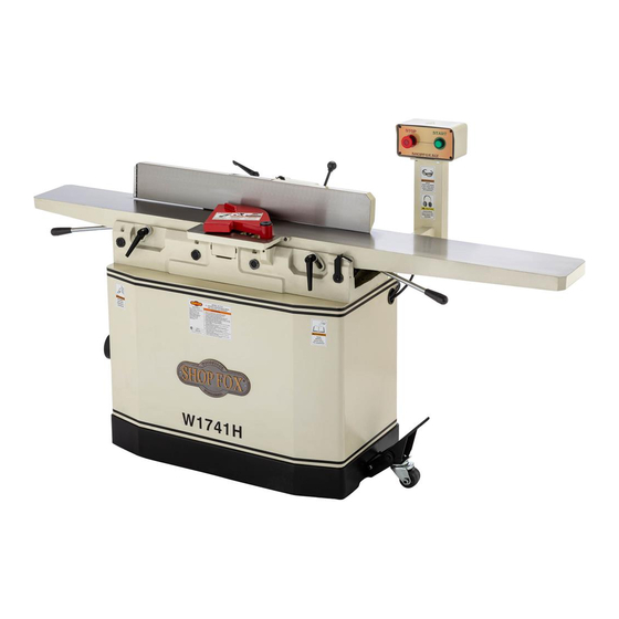
Model W1741H
8" Jointer w/Adjustable Beds
and Helical Cutterhead
Manual Insert
Phone #: (360) 734-3482 • Tech Support: techsupport@woodstockint.com • Web: www.woodstockint.com
The Model W1741H is the same as the Model W1741, except it has a helical cutterhead. Besides the data
sheet and parts in this insert, the content in the Model W1741 owner's manual is the same for both
machines. Before operating your new mach1ine, you MUST read and understand this insert and the entire
Model W1741 manual to reduce the risk of injury from improper use or setup.
If you have any further questions about this manual insert or the differences between the
Model W1741H and the Model W1741, contact our Technical Support at (360) 734-3482 or email
techsupport@woodstockint.com.
COPYRIGHT © FEBRUARY, 2020 BY WOODSTOCK INTERNATIONAL, INC.
WARNING: NO PORTION OF THIS PUBLICATION MAY BE REPRODUCED IN ANY SHAPE OR FORM WITHOUT
THE WRITTEN APPROVAL OF WOODSTOCK INTERNATIONAL, INC.
#20639JL
Printed in China
Advertisement
Table of Contents

Related Manuals for Shop fox W1741H


Summary of Contents for Shop fox W1741H
- Page 1 Phone #: (360) 734-3482 • Tech Support: techsupport@woodstockint.com • Web: www.woodstockint.com The Model W1741H is the same as the Model W1741, except it has a helical cutterhead. Besides the data sheet and parts in this insert, the content in the Model W1741 owner's manual is the same for both machines.
- Page 2 W1741H 8" Jointer with Adjustable Beds and Helical Cutterhead MODEL W1741H 8" JOINTER WITH ADJUSTABLE BEDS AND HELICAL CUTTERHEAD Product Dimensions Weight......................508 lbs. Width (side‐to‐side) x Depth (front‐to‐back) x Height......76‐1/2 x 23‐1/2 x 33 in. Footprint (Length x Width)..............44‐1/2 x 16‐1/2 in.
- Page 3 W1741H 8" Jointer with Adjustable Beds and Helical Cutterhead Main Specifications Main Specifications Bevel Jointing................. 0 – 45 deg. L/R Maximum Width of Cut................... 8 in. Maximum Depth of Cut................1/8 in. Minimum Workpiece Length................10 in. Minimum Workpiece Thickness............... 1/2 in.
-
Page 4: Standard Machinery Safety Instructions
W1741H 8" Jointer with Adjustable Beds and Helical Cutterhead SAFETY SAFETY For Your Own Safety, Read Manual Before Operating Machine The purpose of safety symbols is to attract your attention to possible hazardous conditions. This manual uses a series of symbols and signal words intended to convey the level of importance of the safety messages. - Page 5 W1741H 8" Jointer with Adjustable Beds and Helical Cutterhead WEARING PROPER APPAREL. Do not wear FORCING MACHINERY. Do not force machine. It clothing, apparel, or jewelry that can become will do the job safer and better at the rate for entangled in moving parts.
-
Page 6: Additional Safety For Jointers
W1741H 8" Jointer with Adjustable Beds and Helical Cutterhead Additional Safety for Jointers Serious cuts, amputation, entanglement, or death can occur from contact with rotating cutterhead or other moving components! Flying chips from cutting operations can cause eye injuries or blindness. -
Page 7: Circuit Requirements
W1741H 8" Jointer with Adjustable Beds and Helical Cutterhead ELECTRICAL Circuit Requirements This machine must be connected to the correct size and The machine must be properly set up type of power supply circuit, or fire or electrical damage before it is safe to operate. DO NOT may occur. -
Page 8: Grounding Requirements
W1741H 8" Jointer with Adjustable Beds and Helical Cutterhead Grounding Requirements This machine MUST be grounded. In the event of certain The machine must be properly set up types of malfunctions or breakdowns, grounding provides before it is safe to operate. DO NOT a path of least resistance for electric current to travel—in... - Page 9 W1741H 8" Jointer with Adjustable Beds and Helical Cutterhead Inventory The following is a list of items shipped with your machine. Before beginning setup, lay these items out and inventory them. Note: If you cannot find an item on this list, carefully check around/inside the machine and packaging materials.
- Page 10 W1741H 8" Jointer with Adjustable Beds and Helical Cutterhead Assembly Follow the instructions below before performing any steps in the Assembly section, starting on Page 14 of the W1741 Owner's Manual. Motor Mount Brackets Before beginning the assembly process, refer to Items Needed for Setup and gather everything you need.
- Page 11 W1741H 8" Jointer with Adjustable Beds and Helical Cutterhead Rotating/Replacing Cutterhead Inserts (W1741H) This spiral cutterhead is equipped with indexable carbide Reference inserts. Each insert can be rotated to reveal any one of its four cutting edges. Therefore, if one cutting edge becomes dull or damaged, simply rotate it 90˚, as shown,...
- Page 12 W1741H 8" Jointer with Adjustable Beds and Helical Cutterhead 7. Remove Torx screw and insert, then clean all dust and debris from both parts and pocket they were removed from. Proper cleaning of insert(s), Torx screw, and cutterhead pocket is critical to Tip: Use low-pressure compressed air or vacuum achieving a smooth finish.
-
Page 13: Wiring Diagram
W1741H 8" Jointer with Adjustable Beds and Helical Cutterhead Wiring Diagram Ground 6-20 PLUG 240 VAC CONTROL Ground PANEL 13no (from behind) Contactor 14no Thermal Overload Ground MAGNETIC SWITCH ASSEMBLY Start Capacitor Ground 200MFD 250VAC 240V Capacitor 30MFD MOTOR 450VAC... - Page 14 W1741H 8" Jointer with Adjustable Beds and Helical Cutterhead Stand 35-4 35-2 35-1 35-3 35-6 16 17 28-6 28-8 28-9 28-1 28-3 28-4 28-7 28-10 28-11 28-2 28-5 -14-...
-
Page 15: Stand Parts List
W1741H 8" Jointer with Adjustable Beds and Helical Cutterhead Stand Parts List PART # DESCRIPTION PART # DESCRIPTION X1741H001 FLAT WASHER 5MM 28-11 X1741H028-11 CONTACT PLATE 16MM X1741H002 PANEL X1741H029 CAP SCREW M8-1.25 X 25 X1741H003 FLANGE SCREW M6-1 X 12... - Page 16 W1741H 8" Jointer with Adjustable Beds and Helical Cutterhead Jointer 134 135 -16-...
-
Page 17: Jointer Parts List
W1741H 8" Jointer with Adjustable Beds and Helical Cutterhead Jointer Parts List PART # DESCRIPTION PART # DESCRIPTION X1741H101 KNOB M10-1.5 X1741H155 CAP SCREW M6-1 X 12 X1741H102 STANDOFF STUD X1741H156 CAP SCREW M8-1.25 X 80 X1741H103 BUSHING X1741H157 LOCK WASHER 8MM... -
Page 18: Labels & Cosmetics
W1741H 8" Jointer with Adjustable Beds and Helical Cutterhead Jointer Parts List PART # DESCRIPTION PART # DESCRIPTION X1741H211 ADJUSTING BLOCK X1741H225 HEX WRENCH 8MM X1741H212 HEX NUT M12-1.75 X1741H227 DRIVER BIT TORX T20 X1741H213 LEVER X1741H228 L-WRENCH TORX T20 X1741H214 HANDLE KNOB M12-1.75... -
Page 19: Warranty
Woodstock International, Inc. will repair, replace, or arrange for a dealer refund, at its expense and option, the Shop Fox machine or machine part proven to be defective for its designed and intended use, provided that the original owner returns the product prepaid to an authorized warranty or repair facility as designated by our Bellingham, Washington office with proof of their purchase of the product within two years, and provides Woodstock International, Inc. -
Page 21: Read This First
READ THIS FIRST Model W1741/W1741S ***IMPORTANT UPDATE*** Applies to Models Mfd. Since 4/14 and Owner's Manual February, 2006 Phone #: (360) 734-3482 • Tech Support: tech-support@shopfox.biz • Web: www.shopfox.biz The following changes were made to these machines since the owner's manual was printed: •... -
Page 22: Motor Installation
Model W1741/W1741S (Mfd. Since 4/14) Motor Installation Follow the instructions below before performing any steps in the Assembly section, starting on Page 14 of the W1741 Owner's Manual. To install the motor, do these steps: 1. With the help of another person, tip the stand ship- ping box upside down, then open the bottom of the box to expose the top of the stand. -
Page 23: Standard Machinery Safety Instructions
Model W1741/W1741S (Mfd. Since 4/14) SAFETY SAFETY For Your Own Safety, Read Manual Before Operating Machine The purpose of safety symbols is to attract your attention to possible hazardous conditions. This manual uses a series of symbols and signal words intended to convey the level of importance of the safety messages. - Page 24 Model W1741/W1741S (Mfd. Since 4/14) WEARING PROPER APPAREL. Do not wear FORCING MACHINERY. Do not force machine. It clothing, apparel, or jewelry that can become will do the job safer and better at the rate for entangled in moving parts. Always tie back which it was designed.
-
Page 25: Additional Safety For Jointers
Model W1741/W1741S (Mfd. Since 4/14) Additional Safety for Jointers JOINTER INJURY RISKS. Familiarize yourself with INSPECTING STOCK. To reduce the risk of the main injury risks associated with jointers— kickback injuries or machine damage, always use common sense and good judgement thoroughly inspect and prepare the workpiece to reduce your risk of injury. -
Page 26: Circuit Requirements
Model W1741/W1741S (Mfd. Since 4/14) ELECTRICAL Circuit Requirements This machine must be connected to the correct size and The machine must be properly set up type of power supply circuit, or fire or electrical damage before it is safe to operate. DO NOT may occur. -
Page 27: Grounding Requirements
Model W1741/W1741S (Mfd. Since 4/14) Grounding Requirements This machine MUST be grounded. In the event of certain The machine must be properly set up types of malfunctions or breakdowns, grounding provides before it is safe to operate. DO NOT a path of least resistance for electric current to travel—in connect this machine to the power order to reduce the risk of electric shock. -
Page 28: Wiring Diagram
Model W1741/W1741S (Mfd. Since 4/14) Wiring Diagram Ground 240 VAC 6-20 PLUG CONTROL Ground PANEL 13no (from behind) Contactor 14no Thermal Overload Ground MAGNETIC SWITCH ASSEMBLY Start Capacitor Ground 200MFD 250VAC 240V Capacitor 30MFD MOTOR 450VAC... - Page 29 READ THIS FIRST Model W1741/W1741S ***IMPORTANT UPDATE*** Applies to Models Mfg. Since 7/12 and Owner's Manual February, 2006 Phone #: (360) 734-3482 • Tech Support: tech-support@shopfox.biz • Web: www.shopfox.biz The following changes were recently made to these machines since the owner's manual was printed: •...
- Page 30 Model W1741/W1741S (Mfg. Since 7/12) Motor Installation Follow the instructions below before performing any steps in the Assembly section, starting on Page 14 of the W1741 Owner's Manual. To install the motor, do these steps: 1. With the help of another person, tip the stand ship- ping box upside down, then open the bottom of the box to expose the top of the stand.
- Page 31 Model W1741/W1741S (Mfg. Since 7/12) SAFETY SAFETY For Your Own Safety, Read Manual Before Operating Machine The purpose of safety symbols is to attract your attention to possible hazardous conditions. This manual uses a series of symbols and signal words intended to convey the level of importance of the safety messages.
- Page 32 Model W1741/W1741S (Mfg. Since 7/12) WEARING PROPER APPAREL. Do not wear FORCING MACHINERY. Do not force machine. It clothing, apparel, or jewelry that can become will do the job safer and better at the rate for entangled in moving parts. Always tie back which it was designed.
- Page 33 Model W1741/W1741S (Mfg. Since 7/12) Additional Safety for Jointers JOINTER INJURY RISKS. Familiarize yourself with INSPECTING STOCK. To reduce the risk of the main injury risks associated with jointers— kickback injuries or machine damage, always use common sense and good judgement thoroughly inspect and prepare the workpiece to reduce your risk of injury.
- Page 34 Model W1741/W1741S (Mfg. Since 7/12) ELECTRICAL Circuit Requirements This machine must be connected to the correct size and The machine must be properly set up type of power supply circuit, or fire or electrical damage before it is safe to operate. DO NOT may occur.
- Page 35 Model W1741/W1741S (Mfg. Since 7/12) Grounding Requirements This machine MUST be grounded. In the event of certain The machine must be properly set up types of malfunctions or breakdowns, grounding provides before it is safe to operate. DO NOT a path of least resistance for electric current to travel—in connect this machine to the power order to reduce the risk of electric shock.
- Page 36 Model W1741/W1741S (Mfg. Since 7/12) Wiring Diagram 240 VAC 6-20 PLUG CONTROL PANEL (from behind) MAGNETIC SWITCH ASSEMBLY 240V MOTOR...
-
Page 37: Magnetic Switch
Model W1741 LIGHTED CONTROLS MANUAL UPDATE Improvements to this machine were made since the manual was originally printed, and this update covers those changes. Keep this update with your owner's manual in case you ever need to refer to it. If you have questions, contact Tech Support at (360) 734-3482 or by email at tech_support@shopfox.biz. - Page 38 W1741 Wiring Diagram — February, 2007 ������ ��� ��� ��� ����� ���� ��� ��� ������������ �� ������� ������ ����� ���� ��� ��� ��� ����� ������� ��������� �� ��� ��� ��� ���� � � � � � � � � � �...
- Page 39 Dear Valued Customer, Your new Shop Fox Model W1741 8" Jointer may or may not have switch buttons with light bulbs inside. If your machine does have these type of switch buttons, the light bulb inside is not intended to be functional with your machine and is not wired as such, or displayed in the wiring diagram in your owner's manual.
-
Page 40: Manual Update
Model W1741 8" Jointer Manual Update Why the Update? The motor is now securely bolted to the inside of the stand for shipping purposes. This update covers the setup needed to install the motor in the stand. Use these instructions first, then proceed with the setup as described in the owner's manual. - Page 41 2. Remove the screws that hold the two boards in place, then remove the boards. Your machine is now ready for assembly. Sincerely, The Shop Fox Quality Control Team Woodstock International, Inc. Phone: (800) 840-8420 P.O. Box 2309 FAX: (360) 676-1075 Bellingham, WA 98227 www.woodstockinternational.com...
Need help?
Do you have a question about the W1741H and is the answer not in the manual?
Questions and answers
Where could I buy the motor pulley replacement. ( shop fox W1741)