Table of Contents
Advertisement
Quick Links
For questions on assembly or for general inquiries, you may contact us in the following ways:
Call a Recruiter Today! 734-365-7000
Flexible schedule
*based on number of completed installations
Call Us First!
DO NOT RETURN TO STORE.
Call customer service: 1-877-743-3400
AVOID THE WAIT!
visit us online at
help.backyardproducts.com
Submit a help request
Answers to frequently asked questions
Live chat with an agent
Did you enjoy building your shed?
JOIN OUR TEAM
AND MAKE UP TO $1,500/WEEK*
No selling,
just building
Bonus incentives
available
16572-A
Advertisement
Table of Contents

Related Manuals for Backyard Products 16572-A


Summary of Contents for Backyard Products 16572-A
- Page 1 16572-A Call Us First! DO NOT RETURN TO STORE. For questions on assembly or for general inquiries, you may contact us in the following ways: Call customer service: 1-877-743-3400 AVOID THE WAIT! visit us online at help.backyardproducts.com Submit a help request...
- Page 2 (This page intentionally left blank.)
-
Page 3: Assembly Manual
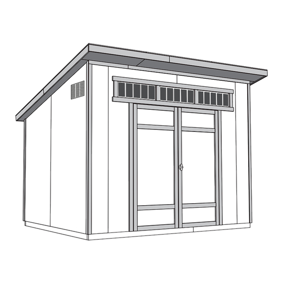
16572-A 09-22-2022 ASSEMBLY MANUAL STUDIO SHED 10' x 7'-6" (304,8 x 228,6 cm) ACTUAL FLOOR SIZE IS 120" x 90" (304,8 x 228,6 cm) KEEP THIS MANUAL FOR FUTURE REFERENCE Two options for door trim. I MPORTA NT ! READ INSTRUCTIONS THOROUGHLY PRIOR TO BEGINNING ASSEMBLY. - Page 4 TOOLS Required Optional Phillips Tool Belt/ Utility Knife Screwdriver Nail Pouch Shingle Blades Drill / Driver 1/4" Drill Bit Tin Snips Caulk Gun (for drip edge) 3/8" Drill Bit 1/2" Drill Bit #2 Philips Drive Bit Chalk Line Paint Tools Hammer Nail Gun •...
-
Page 5: Additional Materials
ADDITIONAL MATERIALS FOUNDATION OR FLOOR MATERIALS • This shed kit includes a complete wood floor system. • This shed kit does not include ANY leveling materials. • See the FLOOR LEVELING section on page 7 for recommended methods and suggested materials to properly level your foor, as this will vary depending on your specific site. -
Page 6: Parts List
PARTS IDENTIFICATION AND SIZES Part identification WOOD SIZE CONVERSION CHART letters are stamped on some parts. Treated lumber is stamped: Nominal Board Size Actual Size 2 x 4....1-1/2" x 3-1/2" (3,8 x 8,9 cm) 1 x 4....3/4" x 3-1/2" (1,9 x 8,9 cm) 2 x 3....1-1/2"... - Page 7 PARTS LIST continued... 2 x 3 x 72" (5,1 x 7,6 x 182,8 cm) 19/32 x 3-1/2 x 80" (1,5 x 8,8 x 203,2 cm) 19/32 x 2-1/2 x 91" (1,5 x 6,3 x 231,1 cm) 2 x 3 x 96" (5,1 x 7,6 x 243,8 cm) 19/32 x 3-1/2 x 96"...
- Page 8 WALL PANEL & DOORS PARTS LIST 3/8 x 23-7/8 x 72" 3/8 x 48 x 72" 3/8 x 11-7/8 x 96" 3/8 x 42 x 83-1/8" 3/8 x 42 x 83-1/8" (1 x 60,6 x 182,9 cm) (1 x 113,3 x 121,9 cm) (1 x 30,1 x 243,8 cm) (1 x 106,6x 211,1 cm) (1 x 106,6x 211,1 cm)
- Page 9 FLOOR LEVELING OPTIONS There are multiple ways to level your floor frame. Our recommended leveling method is shown below. Leveling materials are not included in this kit. PREFERRED METHOD - 4x4 TREATED RUNNERS • 3" Screws angled into 4x4. • (2) at each point frame •...
- Page 10 CONCRETE FOUNDATION Your kit contains all materials to construct a wooden floor. If you choose to install your kit on a concrete slab refer to the diagram below. Treated Sill Plate Caulk between sill plate and concrete. 3-1/2" (8,9 cm) 4"...
-
Page 11: Parts Required
FLOOR FRAME PARTS REQUIRED: 3" (7,6 cm) 2 x 4 x 87" (5,1 x 10,2 x 221 cm) Look for TREATED 2 x 4 x 72" (5,1 x 10,2 x 182,9 cm) Stamp 2 x 4 x 48" (5,1 x 10,2 x 121,9 cm) BEGIN Arrange parts as shown on fl at surface. - Page 12 LEVEL AND SQUARE FLOOR FRAME Before attaching fl oor decking, it is important to level and square the fl oor frame. A level and square fl oor frame is required to correctly construct your shed. BEGIN See page 7 for the preferred fl oor leveling method. Use level and check the frame is level before applying fl oor panels.
- Page 13 FLOOR PANELS PARTS REQUIRED: 2" (5,1 cm) 5/8 x 48 x 96" (1,6 x 121,9 x 243,8 cm) Ensure your floor frame is square by installing one panel and squaring frame. BEGIN Install the 48" x 96" panel with the rough side up (painted-grid lines side) with the 48" edge and corner flush to the floor frame (Fig A).
- Page 14 FLOOR PANELS PARTS REQUIRED: 2" (5,1 cm) 5/8 x 42 x 96" 5/8 x 23-7/8 x 90" (1,6 x 106,7 x 243,8 cm) (1,6 x 60,6 x 228,6 cm) Continue installing panels with rough side up (painted grid lines). Use grid lines on panel during installation. Secure with 2"...
- Page 15 IMPORTANT! Check the foor frame is level after installing foor panels. Re-level if needed. • The foor should be used as a stable work surface for wall construction. • Organize your assembly procedure during the build process HINT: to avoid over-handling of the walls. Back wall Front wall...
- Page 16 BACK WALL FRAME PARTS REQUIRED: 3" (7,6 cm) 2 x 4 x 48" (5,1 x 10,2 x 121,9 cm) 2 x 4 x 64" (5,1 x 10,2 x 162,5 cm) 2 x 4 x 72" (5,1 x 10,2 x 182,9 cm) BEGIN Arrange parts on edge on floor.
- Page 17 BACK WALL PANELS PARTS REQUIRED: 2" (5,1 cm) 3/4" GAUGE 48 x 72" BLOCK (121,9 x 213,4 cm) Install all wall panels with the primed side facing up. Ensure your wall frame is square by installing one panel and squaring frame. Install 48 x 72"...
- Page 18 BACK WALL PANELS PARTS REQUIRED: 2" (5,1 cm) 3/4" GAUGE BLOCK 48 x 72" 23-7/8 x 72" (121,9 x 213,4 cm) (60,6 x 213,4 cm) For squareness maintain 3/4" measurement along panel edges. Flush Install center 48" x 72" panel on frame 4"...
- Page 19 FRONT WALL FRAME PARTS REQUIRED: 3" (7,6 cm) 2 x 4 x 16-1/2" (5,1 x 10,2 x 42 cm) 2 x 4 x 28" (5,1 x 10,2 x 71,2 cm) 2 x 4 x 45-5/8" (5,1 x 10,2 x 115,8 cm) 2 x 4 x 68"...
- Page 20 FRONT WALL FRAME PARTS REQUIRED: 3" (7,6 cm) 2 x 4 x 16" (5,1 x 10,2 x 42 cm) Install parts RD on edge as shown. Measure and mark. HINT: Secure with (2) 3" nails at each mark. For easier nailing stand on frame.
- Page 21 FRONT WALL PANELS PARTS REQUIRED: 2" (5,1 cm) 3/8 x 48 x 96" 3/4" GAUGE (1 x 121,9 x 243,8 cm) BLOCK Install all wall panels with the primed side facing up. Handle panels with care to avoid breakage. Install 48" x 96" left panel primed side up onto wall frame centered in door opening, as shown.
- Page 22 FRONT WALL PANELS PARTS REQUIRED: 2" (5,1 cm) 3/4" GAUGE 3/8 x 48 x 96" BLOCK (1 x 121,9 x 243,8 cm) 3" (7,6 cm) 69" Door Stiffener (175,3 cm) TEMPORARY SUPPORT Install 48 x 96" right panel flush to left panel. Hold the 3/4"...
- Page 23 FRONT WALL PANELS PARTS REQUIRED: 2" (5,1 cm) 3/8 x 11-7/8 x 96" (1 x 30,5 x 243,8 cm) Install 11-7/8 x 96" panel onto wall frame fl ush to installed panel. • Ensure top of panel is overhanging the top of frame by 5-1/2". Secure the panel with 2"...
-
Page 24: Back Wall Installation
BACK WALL INSTALLATION PARTS REQUIRED: 3" (7,6 cm) 2" (5,1 cm) BEGIN Center back wall assembly on the 120" fl oor dimension. 4" (10,2 cm) Secure lower edge of panel to fl oor frame with 2" nails spaced 6" apart. Angle nail into fl oor frame (Fig. - Page 25 FRONT WALL INSTALLATION PARTS REQUIRED (TEMPORARY): 3" (7,6 cm) 2 x 4 x 93-3/16" (5,1 x 10,2 x 236,7 cm) 3" (7,6 cm) 2" (5,1 cm) BEGIN Center front wall assembly on the 120" front fl oor dimension. Use (2) BOA as temporary braces. Level wall and secure BOA with (2) 3"...
- Page 26 WALL DOUBLERS PARTS REQUIRED: 3" (7,6 cm) 2 x 4 x 45-5/8" (5,1 x 10,2 x 115,8 cm) 2 x 4 x 48" (5,1 x 10,2 x 122 cm) 2 x 4 x 72" (5,1 x 10,2 x 182,9 cm) 2 x 4 x 74-1/4"...
- Page 27 OUTER RAFTER INSTALLATION PARTS REQUIRED: 3" (7,6 cm) 2 x 4 x 93-3/16" (5,1 x 10,2 x 236,7 cm) BEGIN Rest one outer rafter on front and back wall doublers. Ensure rafter is fl ush to back wall panel (Fig. A) and fl ush to end of back wall doubler (Fig. B). Secure back of outer rafter with (1) 3"...
- Page 28 RAFTERS PARTS REQUIRED: 3" (7,6 cm) 2 x 4 x 93-3/16" (5,1 x 10,2 x 236,7 cm) BEGIN Measure and mark location of each rafter. Place rafter on front and back wall doublers. Line up rafter centered with marks. Ensure rafter is fl ush to back wall panel (Fig.
-
Page 29: Top View
RAFTER EXTENSIONS PARTS REQUIRED: 3" (7,6 cm) 2 x 3 x 10-1/2" (5,1 x 7,6 x 26,7 cm) BEGIN Locate rafter extension above top of front wall panels (Fig B). Use another rafter extension (BRA) as a guide to line-up rafter extension with top of main rafter (Fig A). Secure rafter extension with (2) 3"... - Page 30 SIDE WALL PANELS PARTS REQUIRED: 2" (5,1 cm) 1-1/2" (3,2 cm) 3/8 x 48 x 96" 3/8 x 48 x 96" 3/8 x 42 x 83" 3/8 x 42 x 83" (1 x 121,9 x 243,8 cm) (1 x 121,9 x 243,8 cm) (1 x 106,7 x 210,9 cm) (1 x 106,7 x 210,9 cm) Install all wall panels with the primed side facing out.
- Page 31 SIDE WALL PANELS (continued) PARTS REQUIRED: 1-1/2" (3,2 cm) 2" (5,1 cm) Secure lower edge of panel to floor with 2" nails spaced 6" apart. Angle nails into floor frame (Fig. A). Secure side wall panels to rafter and wall studs with 1-1/2" nails spaced 6" apart. 6"...
- Page 32 SIDE WALL STUDS PARTS REQUIRED: 3" (7,6 cm) 2 x 4 x 72-5/8" (5,1 x 10,2 x 184,5 cm) 2 x 4 x 79-1/8" (5,1 x 10,2 x 201,3 cm) 2 x 4 x 85-1/2" (5,1 x 10,2 x 217,2 cm) BEGIN Install BJA centered at seam of side wall panels (Fig A).
- Page 33 SIDE WALL PANELS (continued) PARTS REQUIRED: 1-1/2" (3,2 cm) Measure, align and mark side wall studs 24" from center of panel seam, and as shown. Secure side wall panels to inside wall studs with 1-1/2" nails spaced 6" apart along panel seam and 12" apart in middle of panels as shown. 24"...
- Page 34 ROOF PANELS PARTS REQUIRED: 2" (5,1 cm) 3/4" GAUGE BLOCK 7/16 x 48 x 96" (1,1 x 121,9 x 244 cm) Install all roof panels with the rough side up (painted grid lines). Roof panels may cause serious injury until securely fastened. You must square the roof by attaching one panel first.
- Page 35 ROOF PANELS PARTS REQUIRED: x120 2" (5,1 cm) 7/16 x 11-7/8 36-3/8 30,2 92,4 (1,1 x 7/16 x 48 x 96" 7/16 x 36-3/8 x 96" 7/16 x 11-7/8 x 96" (1,1 x 121,9 x 244 cm) (1,1 x 92,4 x 244 cm) (1,1 x 30,2 x 244 cm) Secure the first 48 x 96"...
- Page 36 ROOF PANELS PARTS REQUIRED: 2" (5,1 cm) Line up each rafter extension 90 degrees square with roof rafters as shown. Secure rafter extensions with screws through roof panels (Fig. A). Use 4 screws at roof panel seams (Fig. B). Fig. B Fig.
- Page 37 GABLE RAKE FRAMING PARTS REQUIRED: 2" (5,1 cm) 1 x 3 x 33 - 1/8" (2,5 x 7,6 x 84,1 cm) 1 x 3 x 72" (2,5 x 7,6 x 182,8 cm) Install all trim with the primed side facing out. BEGIN Align BPA edge fl ush with BRA (Fig A).
- Page 38 FRONT EAVE FASCIA TRIM PARTS REQUIRED: 2" (5,1 cm) 19/32 x 3-1/2 x 52 - 3/8" (1,5 x 8,8 x 133 cm) 19/32 x 3-1/2 x 80" (1,5 x 8,8 x 203,2 cm) Install all trim with the primed side facing out. BEGIN Fasten BUA to BRA (Fig.
- Page 39 SIDE FASCIA TRIM ASSEMBLY PARTS REQUIRED: 2" (5,1 cm) 2 x 3 x 33-1/8" (5,1 x 7,6 x 84,1 cm) 19/32 x 3-1/2 x 48" (1,5 x 8,8 x 121,9 cm) 19/32 x 3 - 1/2 x 59 - 1/4" (1,5 x 8,8 x 150,4 cm) 19/32 x 3 - 1/2 x 59 - 1/4"...
- Page 40 SIDE FASCIA TRIM INSTALL PARTS REQUIRED: 2" (5,1 cm) 2" (5,1 cm) Install all trim with the primed side facing out. BEGIN Hold the side fascia assembly fl ush with roof sheathing and front fascia trim (Fig. B). Fig. A Install side fascia assembly underneath roof panels, fl ush with front fascia board.
- Page 41 REAR FASCIA TRIM PARTS REQUIRED: 3" (7,6 cm) 2 x 3 x 35-1/4" (5,1 x 7,6 x 89,5 cm) 2" (5,1 cm) 2" (5,1 cm) 19/32 x 3-1/2 x 35-1/4" (1,5 x 8,8 x 89,5 cm) 2 x 3 x 96" (5,1 x 7,6 x 243,8 cm) 19/32 x 3-1/2 x 96"...
- Page 42 SOFFIT PARTS REQUIRED: 2" (5,1 cm) 35-3/4 x 10-3/8 x 3/8" (90,8 x 26,3 x 1 cm) 95-3/8 x 10-3/8 x 3/8" (242,2 x 26,3 x 1 cm) Install all trim with the primed side facing out. 95-1/2" (242,5 cm) 95-3/8"...
- Page 43 SOFFIT continued..PARTS REQUIRED: 2" (5,1 cm) 95-1/2 x 5-1/4 x 3/8" (242,5 x 13,3 x 1 cm) Install 95-1/2" soffi t board under fascia backer and side rake framing (Fig. C, D). Secure with (14) 2" nails. 2" Finish Flush Flush Nails...
- Page 44 DOORS PARTS REQUIRED: 3" (7,6 cm) 2 x 3 x 69" (5,1 x 7,6 x 175,3 cm) 1-1/4" (3,2 cm) HINT: Look for 3/8" SPACER attached to doors. x1 GAA 1 x 3 x 5" (2,5 x 7,6 x 12,7 cm) Left Door Right Door ¸...
- Page 45 DOORS PARTS REQUIRED: 3" (7,6 cm) 69" Door Stiffener (175,3 cm) Install temporary support OO fl ush under wall panels. Secure with 3" screws (Fig. A). Flush against wall panels Fig. A Center doors on panel seam as shown (Fig. B). Check ledger board is still f ush under panels.
- Page 46 DOOR RAILS - OPTION 1 PARTS REQUIRED: 3/4" (1,9 cm) 19/32" x 3-1/2" x 11-3/8" 19/32 x 2-1/2 x 26-5/8" (1,5 x 6,3 x 67,6 cm) (1,5 x 8,9 x 28,9 cm) See next page for door rails Option 2. BEGIN Secure (2) horizontal door rails AH at measurements shown.
- Page 47 DOOR RAILS - OPTION 2 PARTS REQUIRED: 3/4" (1,9 cm) 19/32" x 3-1/2" x 11-3/8" 19/32 x 2-1/2 x 26-5/8" (1,5 x 6,3 x 67,6 cm) (1,5 x 8,9 x 28,9 cm) BEGIN Secure (4) horizontal door rails AH at measurements shown. Use EHT as a spacer.
- Page 48 DOOR WEATHERSTRIPPING PARTS REQUIRED: 2" (5,1 cm) 69" Door Stiffener (175,3 cm) BEGIN With left door closed, center a weatherstrip OO vertically on the left door in the door opening (Fig. A). OO will offset the left door 1" OUT past the door trim 1" (Fig. B). Secure OO with (5) 3"...
-
Page 49: Door Hardware
DOOR HARDWARE PARTS REQUIRED: 1" (2,5 cm) 5/16" (0,8 cm) Drill Bit BEGIN Install upper spring bolt onto OO in open position with bolt end 3/8" down from frame. Bolt is open when loop is contacting base (Fig A). Mark and pre-drill holes for screws. Secure bolt with screws supplied. -
Page 50: Right Door
DOOR HARDWARE PARTS REQUIRED: 1-1/2" (3,8 cm) 1/2" (1,3 cm) Drill Bit 1/4" (0,6 cm) Drill Bit BEGIN Measure and mark location of hole on outside of right door (Fig. A). Pre-drill hole with 1/4" drill. Re-drill hole with 1/2" drill. Keep drilled hole square to trim to avoid breaking edge of 2x3". - Page 51 WINDOWS PARTS REQUIRED: 3/4" (1,9 cm) 9" x 27" (22,8 x 68,5 cm) ¸ BEGIN Apply high quality exterior-grade caulk behind frame near edge before installing to seal window. From outside of shed, install window in center of opening and level. Secure with (2) screws at top of windows.
- Page 52 WINDOWS TRIM PARTS REQUIRED: 2" (5,1 cm) 19/32 x 2-1/2 x 91" (1,5 x 6,3 x 231,1 cm) 19/32 x 2-1/2 x 9" (1,5 x 6,4 x 22,9 cm) Install all trim with the primed side facing out. Center BSA over door. Secure with (7) 2" finishing nails, as shown. Do not nail into window flange.
- Page 53 WINDOWS PARTS REQUIRED: 3/4" (1,9 cm) Working inside, secure trim with(12) 3/4" screws, as shown. Do not screw into window fl ange. Install 3/4" (1,9 cm) screws from inside. INSIDE FRAMING INSIDE OF SHED Install 3/4" (1,9 cm) screws from inside. You must caulk completely around window frame and all exposed door panel edges and trim to validate your warranty.
- Page 54 BACK CORNER TRIM PARTS REQUIRED: 2" (5,1 cm) 3/8 x 2 x 68-3/4" (0,9 x 5,1 x 174,6 cm) 3/8 x 2 x 69-1/4" (0,9 x 5,1 x 175,8 cm) 3/8 x 2 x 69-1/4" (0,9 x 5,1 x 175,8 cm) Install all trim with the primed side facing out.
- Page 55 FRONT FRIEZE TRIM PARTS REQUIRED: 2" (5,1 cm) 3/8 x 2 x 25-3/8" (0,9 x 5,1 x 64,4 cm) 3/8 x 2 x 96" (0,9 x 5,1 x 243,8 cm) ¸ BEGIN Install 25-3/8" and 96" front horizontal frieze boards. Leave 3/8"...
- Page 56 FRONT CORNER TRIM PARTS REQUIRED: 2" (5,1 cm) 3/8 x 2 x 91-1/4" (0,9 x 5,1 x 231,7 cm) Install all trim with the primed side facing out. ¸ BEGIN Install both vertical 91-1/4" front corner trim on both sides, fl ush to bottom edge of previously installed horizontal frieze trim.
- Page 57 FRONT SIDE TRIM PARTS REQUIRED: 2" (5,1 cm) 3/8 x 2 x 93-1/4" (0,9 x 5,1 x 236,8 cm) 3/8 x 2 x 93-1/4" (0,9 x 5,1 x 236,8 cm) Install all trim with the primed side facing out. ¸ BEGIN Install 93-1/4"...
- Page 58 VENTS PARTS REQUIRED: 1/2" (1,3 cm) 8 x 16" (20,3 x 35,6 cm) ¸ BEGIN Locate and mark for two vents in side walls, as shown; (1) at top and (1) at bottom. Cut out marked openings. Caulk behind vent fl anges. Secure with 1/2"...
- Page 59 PAINT & CAULK - NOT INCLUDED - • Use acrylic latex caulk that is paintable. Caulk at all horizontal and vertical seams, between the trim and walls, and all around the door trim. • Use a high quality exterior acrylic latex paint. When painting your building, there are a few key areas that can be easily overlooked that must be painted: •...
-
Page 60: Start Here
SHINGLES - NOT INCLUDED - • Follow directions provided by manufacturer and these instructions. Familiarize yourself with a 3-Tab Shingle. Notch Notch SHINGLE NAIL PATTERN 1/2" 1" Sealing Strip 1" (1,3 cm) (2,5 cm) (2,5 cm) Half A Rain Slot Full Rain Slot NAILS NEVER DRIVE FASTENERS INTO OR ABOVE SEALING STRIPS. - Page 61 SHINGLES continued... Install second row of shingles flush at top of first row's rain slots. Ensure flush to drip edge at front side, stagger each row. DOOR Notch BACK OF SHED Flush with rain slots. Flush with rain slots. 1" (2,5 cm) Continue installing rows of shingles by staggering at front.
- Page 62 SHINGLES - DRIP EDGE Install drip edge over top shingle row with 1" overhang over roof edge. 1" (2,5 cm) Using your shingle hooked blade carefully cut shingles on a fl at surface along the rain slots, using a chalk line for reference. Align remaining shingles with edge of the front drip edge.
- Page 63 16572-A 10' x 8' Order Form CATEGORY PART DESCRIPTION PART SIZE PART ITEM # BUILDING QTY. PART ID Gable Fascia Backer LUM SPF 2 X 3 X 72 #2&BTR Q 72000000000 Gable Fascia Backer 2 X 3 X 33 1/8" 15* O/E...
- Page 64 LIMITED CONDITIONAL WARRANTY* Backyard Storage Solutions, LLC warrants the following: Every product is warranted from defects in workmanship and manufacturing for 1 year. All accessories, hardware and metal components are warranted for 2 years. All Oriented Strand Board (OSB) is warranted for 2 years Siding and Trim is warranted for 10 years.
Need help?
Do you have a question about the 16572-A and is the answer not in the manual?
Questions and answers