Advertisement
Quick Links
16727
STOP!
STOP!
Call Us First!
DO NOT RETURN TO STORE.
For immediate help with assembly or product information
call our toll-free number:
1-800-577-9663
or email:
customerservice@backyardproductsllc.com
Our staff is ready to provide assistance.
April through October M - F 8:00 AM to 7:00 PM EST
Saturday 8:30 AM to 4:30 PM EST
November through March M - F 8:00 AM to 5:00 PM EST
Advertisement

Subscribe to Our Youtube Channel
Related Manuals for Backyard Products Heartland VALUE Series


Summary of Contents for Backyard Products Heartland VALUE Series
- Page 1 16727 STOP! STOP! Call Us First! DO NOT RETURN TO STORE. For immediate help with assembly or product information call our toll-free number: 1-800-577-9663 or email: customerservice@backyardproductsllc.com Our staff is ready to provide assistance. April through October M - F 8:00 AM to 7:00 PM EST Saturday 8:30 AM to 4:30 PM EST November through March M - F 8:00 AM to 5:00 PM EST...
- Page 2 (This page intentionally left blank.)
-
Page 3: Assembly Manual
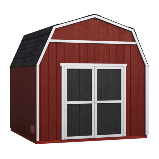
16727 02/17/2011 ASSEMBLY MANUAL A Backyard Products Company VALUE SERIES RAINIER 10' x 10' (305 x 305 cm) ACTUAL FLOOR SIZE IS 120 x 116-5/8" (305 x 296 cm) KEEP THIS MANUAL FOR FUTURE REFERENCE I MPO RTANT ! READ INSTRUCTIONS THOROUGHLY PRIOR TO BEGINNING ASSEMBLY. - Page 4 TOOLS Required Optional Phillips Tool Belt/ Utility Knife Screwdriver Nail Pouch Shingle Blades Drill / Driver Tin Snips 3/8" Drill Bit Caulk Gun (for drip edge) #2 Philips Drive Bit Chalk Line Hammer Paint Tools Level Nail Gun Safety Glasses •...
-
Page 5: Additional Materials
ADDITIONAL MATERIALS FOUNDATION OR FLOOR MATERIALS • This shed kit includes a complete wood Û oor system. • It does not include ANY leveling materials. See the FLOOR LEVELING section on page 8 for recommended methods and suggested materials to properly level your •... -
Page 6: Parts List
PARTS IDENTIFICATION AND SIZES Part identiÚ cation Treated lumber is stamped: WOOD SIZE CONVERSION CHART is stamped on some parts. Nominal Board Size Actual Size 2" x 4"....1-1/2" x 3-1/2" (3,8 x 8,9 cm) 1" x 4"....3/4" x 3-1/2" (1,9 x 8,9 cm) 2"... - Page 7 PANEL PARTS LIST NOTE: Panel parts are not stamped with part identiÀ cation. 5/8 x 23-7/8 x 23-7/8" (1,6 x 61 x 61cm) Floor panels are 5/8 x 23-7/8 x 92-5/8" 5/8" (1,6 cm) thick. (1,6 x 61 x 235 cm) 5/8 x 48 x 92-5/8"...
- Page 8 WALL PANEL & DOORS PARTS LIST NOTE: Panels have a primed side. 3/8 x 23-7/8 x 72" 3/8 x 48 x 72" LEFT DOOR RIGHT DOOR 3/8 x 48 x 96" (1 x 61 x 183 cm) (1 x 122 x 183 cm) (1 x 122 x 244 cm) NAIL BOXES (Shown Actual Size) 3"...
- Page 9 BUILDING ANATOMY This building has been designed using our patented EZ Frame construction method. EZ Frame is a unique construction method which has been engineered to use fewer framing members. This reduces assembly time and cost by as much as 30% compared to conventional construction methods.
- Page 10 FLOOR LEVELING OPTIONS There are multiple ways to level your Û oor frame. Our recommended leveling method is shown below. Leveling materials are not included in this kit. PREFERRED METHOD - 4x4 TREATED RUNNERS Support seam. 4x4 Runners (not included). 8"...
- Page 11 CONCRETE FOUNDATION Your kit contains all materials to construct a wooden Û oor. If you choose to install your kit on a concrete slab refer to the diagram below. Treated Sill Plate Caulk between sill plate and concrete. 3-1/2" (8,9 cm) 4"...
-
Page 12: Parts Required
FLOOR FRAME PARTS REQUIRED: 3" (7,6 cm) x28 TREATED 2 x 4 x 72" (5 x 10 x 183 cm) TREATED NOTE: 2 x 4 x 48" (5 x 10 x 122 cm) Look for Stamp. TREATED 2 x 4 x 21" (5 x 10 x 53 cm) You will build two Û... - Page 13 FLOOR FRAME PARTS REQUIRED: 3" (7,6 cm) x28 TREATED 2 x 4 x 72" (5 x 10 x 183 cm) Treated Wood TREATED 2 x 4 x 89-1/2" (5 x 10 x 227 cm) Treated Wood NOTE: TREATED Look for Stamp.
- Page 14 FLOOR FRAME 3" (7,6 cm) x40 Put both Û oor sections together and attach as shown using 3" nails. FINISH You have Ú nished your Û oor frame. Proceed to level and square frame. (4) Nails per side, stagger pattern. 120"...
- Page 15 FLOOR PANELS PARTS REQUIRED: 2" (5 cm) x55 5/8 x 48 x 92-5/8" (1,6 x 122 x 235 cm) Ensure your Á oor frame is square by installing one panel and squaring frame. BEGIN Attach the 48 x 92-5/8" panel with the rough side up (painted-grid lines side) with the 48"...
- Page 16 FLOOR PANELS PARTS REQUIRED: 5/8 x 23-7/8 x 23-7/8" (1,6 x 61 x 61 cm) 2" (5 cm) x154 5/8 x 23-7/8 x 92-5/8" (1,6 x 61 x 235 cm) 5/8 x 23-7/8 x 96" (1,6 x 61 x 244 cm) 5/8 x 48 x 92-5/8"...
- Page 17 IMPORTANT! I M P O R T A N T ! Check the Á oor frame is level after installing Á oor panels. Re-level if needed. • The Á oor should be used as a level work surface for wall construction. HINT: •...
- Page 18 BACK WALL FRAME PARTS REQUIRED: 3" (7,6 cm) x6 2 x 3 x 48" (5 x 7,6 x 122 cm) 2 x 3 x 94-1/2" (5 x 7,6 x 240 cm) 2 x 3 x 96" (5 x 7,6 x 244 cm) BEGIN Orient parts on edge on Û...
- Page 19 BACK WALL FRAME PARTS REQUIRED: 3" (7,6 cm) x6 3" (7,6 cm) x2 2 x 3 x 45" (5 x 7,6 x 114,3 cm) 2 x 3 x 94-1/2" (5 x 7,6 x 240 cm) Orient parts on edge on Û oor as shown. Nail using two 3"...
- Page 20 BACK WALL PANELS PARTS REQUIRED: 2" (5 cm) x44 3/8 x 48 x 96" (1 x 122 x 244 cm) 3/4" GAUGE BLOCK BEGIN Place panel on back frame as shown with primed side facing up. Note: Orient square and lip edges as shown. Do not nail in groove.
- Page 21 BACK WALL PANELS PARTS REQUIRED: 2" (5 cm) x44 3/4" 3/8 x 48 x 96" (1 x 122 x 244 cm) GAUGE BLOCK Place panel on back frame as shown with primed side facing up. Note: Orient square and lip edges as shown. Do not nail Use a 3/4"...
- Page 22 WING WALL PANELS PARTS REQUIRED: 1-1/4" (3 cm) x32 LEFT RIGHT 2 x 3 x 72-5/8" (5 x 7,6 x 184,5 cm) BEGIN You will assemble TWO RIGHT and TWO LEFT wing walls. Place OB on Û oor. Place a wing wall panel primed side down onto OB (Fig.A) . Secure Û...
- Page 23 BACK WALL PARTS REQUIRED: 2" (5 cm) x34 Pre-assembled LEFT RIGHT Pre-assembled Place wing wall assemblies onto frame with top of panels Û ush (Fig.A) . Nail left and right wing wall assemblies onto back wall frame using 2" nails 6" apart. Do not nail in groove.
- Page 24 GABLE PANELS AND TRIM PARTS REQUIRED: 1-1/4" (3 cm) x24 2 x 3 x 45-1/8" (5 x 7,6 x 115 cm) LEFT RIGHT BEGIN You will be attaching trim PD from the backside of the gable panels (Fig. A) . You will assemble TWO RIGHT and TWO LEFT assemblies.
- Page 25 BACK WALL GABLE PANELS PARTS REQUIRED: 2" (5 cm) x24 2 x 3 x 25" (5 x 7,6 x 63,5 cm) 3" (7,6 cm) x2 LEFT RIGHT Pre-assembled Pre-assembled 1-1/2" (3,8 cm) 48-3/4" 48-3/4" (124 cm) (124 cm) Screws 3" (7,6 cm) BEGIN Center CO on edge onto wall frame and...
- Page 26 FRONT WALL FRAME PARTS REQUIRED: 3" (7,6 cm) x12 2 x 3 x 22-1/2" (5 x 7,6 x 57 cm) 2 x 3 x 94-1/2" (5 x 7,6 x 240 cm) 2 x 3 x 96" (5 x 7,6 x 244 cm) BEGIN Lay out two PR, two PT and one LV on edge on Û...
- Page 27 FRONT WALL PANELS PARTS REQUIRED: 2" (5 cm) x36 3/4" GAUGE LEFT BLOCK BEGIN Place LEFT panel on front frame as shown with primed side facing up. Use a 3/4" gauge block on edges of panel. Nail panel to frame with 2" nails 6" apart. Do not nail in groove.
- Page 28 FRONT WALL PANELS PARTS REQUIRED: 2" (5 cm) x36 3/4" GAUGE BLOCK RIGHT Place RIGHT panel on front frame. Use a 3/4" gauge block on edges of panel. Nail panel to frame with 2" nails 6" apart. Do not nail in groove.
- Page 29 FRONT WALL PANELS PARTS REQUIRED: 2" (5 cm) x34 Pre-assembled LEFT RIGHT Pre-assembled Place wing wall panels onto frame with top of panels (Fig. A) . Nail left and right wing wall assemblies using 2" nails 6" apart. Do not nail in groove.
- Page 30 FRONT WALL GABLE PANELS PARTS REQUIRED: 2" (5 cm) x24 2 x 3 x 25" (5 x 7,6 x 63,5 cm) 3" (7,6 cm) x2 LEFT RIGHT Pre-assembled Pre-assembled 1-1/2" (3,8 cm) 48-3/4" 48-3/4" (124 cm) (124 cm) Screws 3" (7,6 cm) BEGIN Center CO on edge onto wall frame and...
- Page 31 SIDE WALL FRAMES PARTS REQUIRED: 3" (7,6 cm) x20 2" x 3" x 46-1/4" (5 x 7,6 x 117 cm) 2" x 3" x 68-3/4 " (5 x 7,6 x 174,6 cm) 2" x 3" x 70-1/4" (5 x 7,6 x 178 cm) BEGIN Orient parts on edge on Û...
- Page 32 SIDE WALL PANELS PARTS REQUIRED: 2" (5 cm) x34 3/4" GAUGE BLOCK 3/8 x 48 x 72" (1 x 122 x 183 cm) Ensure your wall frame is square by installing one panel and squaring frame. Place the 48 x 72" panel onto wall frame with primed side up as shown. Note the lip and square edges.
- Page 33 SIDE WALL PANELS PARTS REQUIRED: 2" (5 cm) x166 3/8 x 23-7/8 x 72" (1 x 61 x 183 cm) 3/8" x 48" x 72" 3/4" GAUGE (1 x 122 x 183 cm) BLOCK For squareness maintain 3/4" and 5/8" measurement along panel edge. To draw panels tight at seams angle nail.
-
Page 34: Back Wall Installation
BACK WALL INSTALLATION PARTS REQUIRED (TEMPORARY): 3" (7,6 cm) x8 1 x 4 x 96" (2,5 x 10 x 244 cm) 2" (5 cm) x24 BEGIN Center back wall assembly on the 120" (305 cm) Û oor dimension. Use KP as a temporary brace. Secure with two 3" screws. (2) 3"... - Page 35 SIDE WALLS INSTALLATION 3" (7,6 cm) x4 3" (7,6 cm) x20 2" (5 cm) x70 BEGIN Stand right sidewall on Û oor. It is important to secure the sidewall in the following order. Center sidewall on Û oor front to back.
- Page 36 FRONT WALL INSTALLATION 3" (7,6 cm) x8 2" (5 cm) x38 BEGIN Stand frontwall on Û oor. It is important to secure the frontwall in the following order. Center frontwall on Û oor side-to-side. Nail the frontwall Û ush to the Û oor using 2"...
- Page 37 GABLE TRIM PARTS REQUIRED: 1-1/4" (3 cm) x24 2 x 3 x 41" (5 x 7,6 x 104 cm) BEGIN Install front lower gable trim PF so two points contact PD and corner trim OB as shown. Secure PF to wall using six 1-1/4" screws 7-1/2" apart. Screw through panels into PF (Fig A) .
- Page 38 RAFTERS PARTS REQUIRED: 2" (5 cm) x96 Pre-assembled GUSSET RAFTER-HALF BEGIN You will build FOUR assemblies; Place two rafter-halves in the corner of back and side walls. The RED ENDS identify the ends to be connected at the center. HINT: Use Á...
- Page 39 RAFTERS PARTS REQUIRED: 3" (7,6 cm) x16 Rafter Assemblies BEGIN Arrange four rafters centered on the mark you made for locating the wall studs. (Fig. A) . The rafters also line up directly over the wall studs. Check you have the measurements shown. Attach with two 3"...
- Page 40 LOFT JOISTS PARTS REQUIRED: 3" (7,6 cm) x8 2 x 4 x 59-3/4" (5 x 10 x 152 cm) BEGIN Install SU at same height as top plates and level. Install using two 3" nails at each connection, as shown. BACK WALL 1/4"...
- Page 41 LOFT JOISTS PARTS REQUIRED: 3" (7,6 cm) x24 2 x 4 x 27-1/2" (5 x 10 x 70 cm) 2 x 4 x 92" (5 x 10 x 234 cm) You will construct FOUR Loft Joist sub-assemblies. Glue PW onto VU as shown. For best results use an exterior grade wood glue. Nail PW onto VU using six 3"...
- Page 42 LOFT JOISTS 3" (7,6 cm) x22 Take two loft joist sub-assemblies and Û ip one end to end so they will produce a 4" x 4" loft joist. Spread glue on the surfaces which come into contact with one another as shown. Nail the two sub-assemblies together using eleven 3"...
- Page 43 LOFT JOISTS PARTS REQUIRED: 3" (7,6 cm) x8 ASSEMBLED LOFT JOIST BEGIN Put a loft joist Û ush on the front side of each of the back two rafters. Attach each joist with one 3" screw angled through the joist into the top plate. Then, screw through rafter into the loft joist with one 3"...
- Page 44 LOFT PANEL PARTS REQUIRED: 2" (5 cm) x4 7/16 x 48 x 96" (1 x 122 x 244 cm) BEGIN Place loft panel grid lines up onto the three loft joists centered from side-to-side and Û ush with the back wall frame. IMPORTANT! Using only FOUR 2"...
- Page 45 ROOF PANELS PARTS REQUIRED: 2" (5 cm) x196 3/4" GAUGE 7/16 x 41-7/8 x 96" 7/16 x 45-1/8 x 96" BLOCK (1,1 x 106 x 244 cm) (1,1 x 115 x 244 cm) 7/16 x 23-7/8 x 41-7/8" 7/16 x 23-7/8 x 45-1/8" (1,1 x 61 x 106 cm) (1,1 x 61 x 115 cm) Roof panels may cause serious injury...
- Page 46 ROOF PANELS PARTS REQUIRED: 3/4" GAUGE BLOCK Keep spacing between the center of the rafters at the lower edge of the panel and secure with one 2" nail into 6" (15 cm) each rafter (Fig. E). Move to the top of the panel and 12"...
- Page 47 LOFT PANEL 2" (5 cm) x11 BEGIN Complete installation of Loft panel using 2" nails spaced 24". FINISH You have Ú nished your loft panel 2" (5 cm) Attention: Load not to exceed 400 lbs (181 kg) evenly distributed across Loft.
- Page 48 DOORS PARTS REQUIRED: 1-1/4" (3 cm) x4 1 x 4 x 96" (2,5 x 10 x 244 cm) 2" (5 cm) x4 HINT: Look for 3/8" SPACER attached to doors. Left Door Right Door BEGIN 3/8" offset is to top. Look for red Orient parts as shown on Û...
- Page 49 DOORS PARTS REQUIRED: 3" (7,6 cm) x7 2 x 3 x 69" (5 x 7,6 x 175,3 cm) Attach temporary support OO as a ledger board Û ush under wall panels for doors to rest on, using three 3" screws (Fig. A) . Flush against wall panels.
- Page 50 DOOR PARTS REQUIRED: 2" (5 cm) x8 3/4" (1,9 cm) x50 5/8 x 3 x 72" (1,6 x 7,6 x 183 cm) 3/4" (1,9 cm) x11 Bagged seperately / 64" Metal Threshold special coating Secure hinge boards from inside using 3/4" screws as shown (Fig. A). Reinforce the door trim using 3/4"...
- Page 51 DOOR WEATHERSTRIP PARTS REQUIRED: 2" (5 cm) x14 2 x 3 x 69" (5 x 7,6 x 175 cm) BEGIN With left door closed, center a weatherstrip OO vertically on the left door in the door opening (Fig. A ). OO will offset the left door 1" OUT past the door trim 1"...
-
Page 52: Door Hardware
DOOR HARDWARE PARTS REQUIRED: 3/8" (9 mm) Drill Bit 3/4" (1,9 cm) x4 3/4" (1,9 cm) x7 BEGIN Mount barrel bolt Û ush at top of OO on left door using 3/4" screws as shown (Fig A) . With door closed mark hole location for bolt to extend into. HINT: Extend bolt to leave a mark in wood. - Page 53 COLLAR TIES PARTS REQUIRED: 2" (5 cm) x12 1 x 4 x 96" (2,5 x 10 x 244 cm) BEGIN Install a collar tie KP on the two rafters closest to the door opening. Use three 2" nails at each side of collar tie. Collar ties should be Û ush to the roof panels.
- Page 54 TRIM PARTS REQUIRED: 2" (5 cm) x20 1 x 3 x 94-1/2" (2,5 x 7,6 x 240 cm) BEGIN Install HQ over seam of front wall panels using 2" Ú nishing nails as shown. Repeat Step 1 installing HQ over seam at back side. FINISH You have Ú...
- Page 55 PAINT & CAULK - NOT INCLUDED - • Use acrylic latex caulk that is paintable. Caulk at all horizontal and vertical seams, between the trim and walls, and all around the door trim. • Use a high quality exterior acrylic latex paint. When painting your building, there are a few key areas that can be easily overlooked that must be painted: •...
- Page 56 SHINGLES - NOT INCLUDED - • Follow directions provided by manufacturer and these instructions. Familiarize yourself with a 3-Tab Shingle. Notch Notch SHINGLE NAIL PATTERN 1/2" 1" Sealing Strip 1" (1,3 cm) (2,5 cm) (2,5 cm) Half A Rain Slot Full Rain Slot NAILS NEVER DRIVE FASTENERS INTO OR ABOVE SEALING STRIPS.
- Page 57 SHINGLES continued... Install second row of shingles Û ush at top of Ú rst row's rain slots. Ensure 1" overhang or Û ush to drip edge at front, stagger each row. FRONT OF BACK OF SHED SHED Bend in roof 1"...
- Page 58 SHINGLES continued... After shingles are installed over bend, nail down overlap using two rooÚ ng nails per tab. (2) Nails per tab. Continue installing rows of shingles to the peak. At the peak make sure there is a maximum of 5" or less to the rain slot, as shown below.
- Page 59 SHINGLES - RIDGE CAP • You will Ú nish off the top of the roof with a ridge cap made from shingles. BEGIN Hint: Cut shingles into THREE pieces. Use cut-off pieces Ú rst. 2" 2" (5 cm) (5 cm 2"...
- Page 60 SHINGLES - RIDGE CAP continued... Continue installing ridge cap to back of roof. Make sure there is 4" between the shingle-color and edge of shingles. 4" (10 cm) Trim cap off Á ush to shingles When you have 4" minimum of shingle color cut one piece to cap your roof. Cut at top of rain slot.
- Page 61 WARRANTY Backyard Storage Solutions, LLC warrants the following: Limited Conditional Every product is warranted from defects in workmanship and manufacturing for one year. Warranty * All hardware and metal components are warranted for two years. Trim is warranted for 10 years. Waferboard siding and sheathing is warranted for two years.
Need help?
Do you have a question about the Heartland VALUE Series and is the answer not in the manual?
Questions and answers