Table of Contents
Advertisement
Quick Links
Advertisement
Chapters
Table of Contents

Subscribe to Our Youtube Channel
Related Manuals for Beckhoff EL95 Series


Summary of Contents for Beckhoff EL95 Series
- Page 1 Documentation EL95xx Power supply terminals Version: Date: 2019-07-02...
- Page 3 Product overview – EtherCAT power supply terminals Product overview – EtherCAT power supply terminals EL9505 [} 12] (power supply terminal, 5 V , 0.5 A) EL9508 [} 12] (power supply terminal, 8 V , 0.5 A) EL9510 [} 12] (power supply terminal, 10 V , 0.5 A) EL9512 [} 12] (power supply terminal, 12 V , 0.5 A) EL9515 [} 12] (power supply terminal, 15 V , 0.5 A)
-
Page 4: Table Of Contents
Table of contents Table of contents 1 Product overview – EtherCAT power supply terminals ................. 3 2 Foreword .............................. 5 Notes on the documentation...................... 5 Safety instructions .......................... 6 Documentation issue status ...................... 7 Version identification of EtherCAT devices .................. 7 3 Product overview............................. 12 Introduction ............................ 12 EL9505, EL9508, EL9510, EL9512, EL9515 - Technical data ............ 13 EL9560 - Technical data........................ 14 4 Basics communication ........................... 15... -
Page 5: Foreword
The TwinCAT Technology is covered, including but not limited to the following patent applications and patents: EP0851348, US6167425 with corresponding applications or registrations in various other countries. ® EtherCAT is registered trademark and patented technology, licensed by Beckhoff Automation GmbH, Germany. Copyright © Beckhoff Automation GmbH & Co. KG, Germany. -
Page 6: Safety Instructions
All the components are supplied in particular hardware and software configurations appropriate for the application. Modifications to hardware or software configurations other than those described in the documentation are not permitted, and nullify the liability of Beckhoff Automation GmbH & Co. KG. Personnel qualification This description is only intended for trained specialists in control, automation and drive engineering who are familiar with the applicable national standards. -
Page 7: Documentation Issue Status
• EL9560 added • First published • Corrections and addenda • Provisional documentation for EL95xx Version identification of EtherCAT devices Designation A Beckhoff EtherCAT device has a 14-digit designation, made up of • family key • type • version • revision Example... - Page 8 Production lot/batch number/serial number/date code/D number The serial number for Beckhoff IO devices is usually the 8-digit number printed on the device or on a sticker. The serial number indicates the configuration in delivery state and therefore refers to a whole production batch, without distinguishing the individual modules of a batch.
-
Page 9: Fig. 1 El5021 El Terminal, Standard Ip20 Io Device With Serial/ Batch Number And Revision Id (Since 2014/01)
Foreword Examples of markings Fig. 1: EL5021 EL terminal, standard IP20 IO device with serial/ batch number and revision ID (since 2014/01) Fig. 2: EK1100 EtherCAT coupler, standard IP20 IO device with serial/ batch number Fig. 3: CU2016 switch with serial/ batch number EL95xx Version: 2.2... -
Page 10: Fig. 4 El3202-0020 With Serial/ Batch Number 26131006 And Unique Id-Number 204418
Foreword Fig. 4: EL3202-0020 with serial/ batch number 26131006 and unique ID-number 204418 Fig. 5: EP1258-00001 IP67 EtherCAT Box with batch number/ date code 22090101 and unique serial number 158102 Fig. 6: EP1908-0002 IP67 EtherCAT Safety Box with batch number/ date code 071201FF and unique serial number 00346070 Fig. 7: EL2904 IP20 safety terminal with batch number/ date code 50110302 and unique serial number 00331701... -
Page 11: Fig. 8 Elm3604-0002 Terminal With Unique Id Number (Qr Code) 100001051 And Serial/ Batch Num- Ber 44160201
Foreword Fig. 8: ELM3604-0002 terminal with unique ID number (QR code) 100001051 and serial/ batch number 44160201 EL95xx Version: 2.2... -
Page 12: Product Overview
Product overview Product overview Introduction Fig. 9: Left: EL9505 (identical pin assignment: EL9508, EL9510, EL9512, EL9515) Right: EL9560 Based on the input voltage (24 V ), the EL9505, EL9508, EL9510, EL9512 and EL9515 power supply terminals generate different output voltages, which can be picked up at the terminals. The following EtherCAT Terminals are also supplied with this voltage via the power contacts. -
Page 13: El9505, El9508, El9510, El9512, El9515 - Technical Data
Product overview EL9505, EL9508, EL9510, EL9512, EL9515 - Technical data Technical data EL9505 EL9508 EL9510 EL9512 EL9515 Input voltage 24 V Output voltage 5 V ±1% 8 V ±1% 10 V ±1% 12 V ±1% 15 V ±1% Output current 0.5 A Short circuit diagnosis, overload: Overcurrent LED Short circuit proof Message to E-bus... -
Page 14: El9560 - Technical Data
Product overview EL9560 - Technical data Technical data EL9560 Input voltage 24 V (-15 %/+20 %) Output voltage 24 V (-15 %/+5 %) Output current 0.1 A Short circuit proof Message to E-bus Power contacts (right) , 0 V, PE E-Bus current consumption 90 mA typ. Bit width in process image Electrical connection to mounting rail Isolation voltage... -
Page 15: Basics Communication
EtherCAT devices from Beckhoff. Recommended cables Suitable cables for the connection of EtherCAT devices can be found on the Beckhoff website! E-Bus supply A bus coupler can supply the EL terminals added to it with the E-bus system voltage of 5 V; a coupler is thereby loadable up to 2 A as a rule (see details in respective device documentation). -
Page 16: Ethercat State Machine
Basics communication Fig. 10: System manager current calculation NOTE Malfunction possible! The same ground potential must be used for the E-Bus supply of all EtherCAT terminals in a terminal block! EtherCAT State Machine The state of the EtherCAT slave is controlled via the EtherCAT State Machine (ESM). Depending upon the state, different functions are accessible or executable in the EtherCAT slave. -
Page 17: Coe Interface
Basics communication Init After switch-on the EtherCAT slave in the Init state. No mailbox or process data communication is possible. The EtherCAT master initializes sync manager channels 0 and 1 for mailbox communication. Pre-Operational (Pre-Op) During the transition between Init and Pre-Op the EtherCAT slave checks whether the mailbox was initialized correctly. -
Page 18: Fig. 12 "Coe Online " Tab
Basics communication The order is specified in 2 levels via hexadecimal numbering: (main)index, followed by subindex. The value ranges are • Index: 0x0000 …0xFFFF (0...65535 • SubIndex: 0x00…0xFF (0...255 A parameter localized in this way is normally written as 0x8010:07, with preceding "x" to identify the hexadecimal numerical range and a colon between index and subindex. - Page 19 Changes in the local CoE list of the terminal are lost if the terminal is replaced. If a terminal is re- placed with a new Beckhoff terminal, it will have the default settings. It is therefore advisable to link all changes in the CoE list of an EtherCAT slave with the Startup list of the slave, which is pro- cessed whenever the EtherCAT fieldbus is started.
-
Page 20: Fig. 13 Startup List In The Twincat System Manager
Basics communication Fig. 13: Startup list in the TwinCAT System Manager The Startup list may already contain values that were configured by the System Manager based on the ESI specifications. Additional application-specific entries can be created. Online/offline list While working with the TwinCAT System Manager, a distinction has to be made whether the EtherCAT device is "available", i.e. -
Page 21: Fig. 15 Online List
• Channel 1: parameter range 0x8010:00 ... 0x801F:255 • Channel 2: parameter range 0x8020:00 ... 0x802F:255 • ... This is generally written as 0x80n0. Detailed information on the CoE interface can be found in the EtherCAT system documentation on the Beckhoff website. EL95xx Version: 2.2... -
Page 22: Mounting And Wiring
• Each assembly must be terminated at the right hand end with an EL9011 or EL9012 bus end cap, to en- sure the protection class and ESD protection. Fig. 16: Spring contacts of the Beckhoff I/O components Installation on mounting rails... -
Page 23: Fig. 17 Attaching On Mounting Rail
Mounting and wiring Assembly Fig. 17: Attaching on mounting rail The bus coupler and bus terminals are attached to commercially available 35 mm mounting rails (DIN rails according to EN 60715) by applying slight pressure: 1. First attach the fieldbus coupler to the mounting rail. 2. -
Page 24: Fig. 18 Disassembling Of Terminal
Mounting and wiring Disassembly Fig. 18: Disassembling of terminal Each terminal is secured by a lock on the mounting rail, which must be released for disassembly: 1. Pull the terminal by its orange-colored lugs approximately 1 cm away from the mounting rail. In doing so for this terminal the mounting rail lock is released automatically and you can pull the terminal out of the bus terminal block easily without excessive force. -
Page 25: Fig. 19 Power Contact On Left Side
Mounting and wiring Fig. 19: Power contact on left side NOTE Possible damage of the device Note that, for reasons of electromagnetic compatibility, the PE contacts are capacitatively coupled to the mounting rail. This may lead to incorrect results during insulation testing or to damage on the terminal (e.g. disruptive discharge to the PE line during insulation testing of a consumer with a nominal voltage of 230 V). -
Page 26: Installation Instructions For Enhanced Mechanical Load Capacity
Mounting and wiring Installation instructions for enhanced mechanical load capacity WARNING Risk of injury through electric shock and damage to the device! Bring the Bus Terminal system into a safe, de-energized state before starting mounting, disassembly or wiring of the Bus Terminals! Additional checks The terminals have undergone the following additional tests: Verification... -
Page 27: Fig. 20 Standard Wiring
Mounting and wiring Standard wiring Fig. 20: Standard wiring The terminals of KLxxxx and ELxxxx series have been tried and tested for years. They feature integrated screwless spring force technology for fast and simple assembly. Pluggable wiring Fig. 21: Pluggable wiring The terminals of KSxxxx and ESxxxx series feature a pluggable connection level. The assembly and wiring procedure for the KS series is the same as for the KLxxxx and ELxxxx series. -
Page 28: Fig. 23 Mounting A Cable On A Terminal Connection
Mounting and wiring Wiring HD Terminals The High Density (HD) Terminals of the KLx8xx and ELx8xx series doesn't support steady wiring. Ultrasonically "bonded" (ultrasonically welded) conductors Ultrasonically “bonded" conductors It is also possible to connect the Standard and High Density Terminals with ultrasonically "bonded"... - Page 29 Mounting and wiring Terminal housing High Density Housing Wire size width (conductors with a wire end sleeve) 0.14 ... 0.75 mm Wire size width (single core wires) 0.08 ... 1.5 mm Wire size width (fine-wire conductors) 0.25 ... 1.5 mm Wire size width (ultrasonically “bonded" conductors) only 1.5 mm (see notice [} 28]!) Wire stripping length...
-
Page 30: Positioning Of Passive Terminals
Mounting and wiring Positioning of passive Terminals Hint for positioning of passive terminals in the bus terminal block EtherCAT Terminals (ELxxxx / ESxxxx), which do not take an active part in data transfer within the bus terminal block are so called passive terminals. The passive terminals have no current consump- tion out of the E-Bus. -
Page 31: Atex - Special Conditions (Standard Temperature Range)
80°C at the wire branching points, then cables must be selected whose tempera- ture data correspond to the actual measured temperature values! • Observe the permissible ambient temperature range of 0 to 55°C for the use of Beckhoff fieldbus compo- nents standard temperature range in potentially explosive areas! •... -
Page 32: Atex Documentation
Notes about operation of the Beckhoff terminal systems in potentially explosive ar- eas (ATEX) Pay also attention to the continuative documentation Notes about operation of the Beckhoff terminal systems in potentially explosive areas (ATEX) that is available in the download area of the Beckhoff homepage http:\\www.beckhoff.com! Version: 2.2... -
Page 33: Ul Notice
Beckhoff EtherCAT modules are intended for use with Beckhoff’s UL Listed EtherCAT Sys- tem only. Examination For cULus examination, the Beckhoff I/O System has only been investigated for risk of fire and electrical shock (in accordance with UL508 and CSA C22.2 No. 142). For devices with Ethernet connectors Not for connection to telecommunication circuits. -
Page 34: Pin Assignment
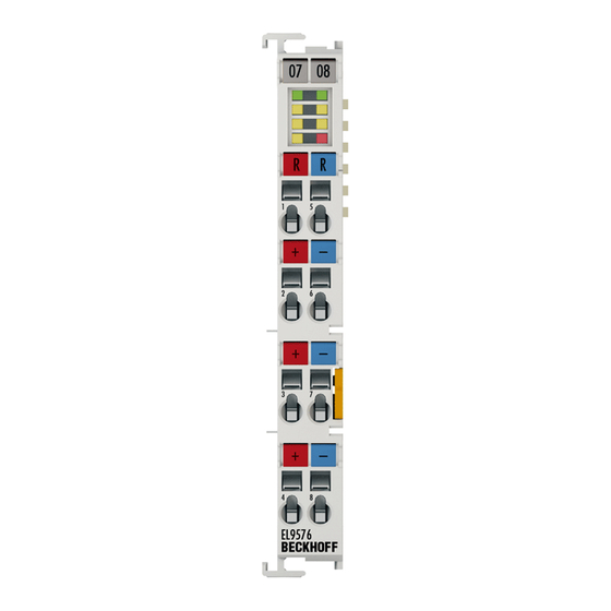
Mounting and wiring Pin assignment Fig. 26: Pin assignment based on EL9505 as an example Terminal point Description Name +24 V +24 V input voltage Output U Pickup of output voltage U (linked to terminal point 6 and power contact U 0 ... -
Page 35: Commissioning
Installation of the latest XML device description Please ensure that you have installed the corresponding latest XML device description in TwinCAT. This can be downloaded from the Beckhoff Website and installed according to the installation in- structions. The configuration tree in the Beckhoff TwinCAT System Manager can be created in 2 ways: •... -
Page 36: Fig. 28 Appending A New I/O Device (I/O Devices-> Right-Click -> Append Device
Commissioning Fig. 28: Appending a new I/O device (I/O Devices-> right-click -> Append Device...) Fig. 29: Selecting the device EtherCAT (Direct Mode) • Appending a new box (see Fig. Appending a new box (Device -> right click -> Append Box…)). In the dialog that follows select an EK1100 system coupler, for example (see Fig. -
Page 37: Fig. 31 Selecting A System Coupler (E.g. Ek1100)
Commissioning Fig. 31: Selecting a system coupler (e.g. EK1100) • Appending a new box (see Fig. Appending a new box (Device -> right click -> Append Box…)). In the dialog that follows select the EL95xx, (see Fig. Selecting the terminal, e.g. EL9505) and confirm with •... -
Page 38: Process Data
Commissioning Fig. 33: Selecting the terminal, e.g. EL9505 Fig. 34: Terminal in the TwinCAT tree Process data The "Process Data" tab of the EL95xx in the TwinCAT System Manager shows the PDO list of the EL95xx with the corresponding input objects. The width in the process image is 2 bits. The index 0x1A00 ("Status U ") contains the two boolean input objects "Power OK"... -
Page 39: Fig. 35 El95Xx - "Process Data" Tab
Commissioning Fig. 35: EL95xx – "Process Data" tab EL95xx Version: 2.2... -
Page 40: Appendix
Appendix Appendix Firmware compatibility The terminals of the EL95xx series have no firmware. Version: 2.2 EL95xx... -
Page 41: Support And Service
Beckhoff's branch offices and representatives Please contact your Beckhoff branch office or representative for local support and service on Beckhoff products! The addresses of Beckhoff's branch offices and representatives round the world can be found on her internet pages: http://www.beckhoff.com You will also find further documentation for Beckhoff components there. - Page 42 Startup list in the TwinCAT System Manager ................Fig. 14 Offline list ............................. Fig. 15 Online list ............................ Fig. 16 Spring contacts of the Beckhoff I/O components................. Fig. 17 Attaching on mounting rail ......................Fig. 18 Disassembling of terminal......................Fig. 19 Power contact on left side......................
Need help?
Do you have a question about the EL95 Series and is the answer not in the manual?
Questions and answers