
Related Manuals for Beckhoff PS1011-2410-0000


Summary of Contents for Beckhoff PS1011-2410-0000
- Page 1 Documentation | EN PS1011-2410-0000 Power supply 24 V DC, 10 A, 1-phase 2020-10-27 | Version: 1.0...
-
Page 3: Table Of Contents
Parallel use to increase power ...................... 28 Series connection .......................... 28 Inductive and capacitive loads...................... 28 Charging batteries ........................... 29 Operation on two phases......................... 29 Use in a tightly sealed enclosure ..................... 29 5 Appendix .............................. 30 Documentation issue status ...................... 30 Support and Service ........................ 31 PS1011-2410-0000 Version: 1.0... - Page 4 Table of contents Version: 1.0 PS1011-2410-0000...
-
Page 5: Overview
• Full power between -25°C and +55°C • DC-OK relay contact The PS1011-2410-0000 is a 1-phase 24 V power supply with an output current of 10 A and an output power of 240 W. On the input side, the device features a wide-range input, active power factor correction (PFC) and inrush current limiting. -
Page 6: Foreword
, XFC , XTS and XPlanar are registered trademarks of and licensed by Beckhoff Automation GmbH. Other designations used in this publication may be trademarks whose use by third parties for their own purposes could violate the rights of the owners. -
Page 7: Terminology And Abbreviations
50 Hz. AC 120 V parameters are valid for a mains frequency of 60 Hz. A keyword indicating a choice without implied preference. shall A keyword indicating a mandatory requirement. should A keyword indicating a choice with a clearly preferred method of implementation. PS1011-2410-0000 Version: 1.0... -
Page 8: Safety Instructions
All the components are supplied in particular hardware and software configurations appropriate for the application. Modifications to hardware or software configurations other than those described in the documentation are not permitted, and nullify the liability of Beckhoff Automation GmbH & Co. KG. Personnel qualification This description is only intended for trained specialists in control, automation and drive engineering who are familiar with the applicable national standards. - Page 9 Foreword Safety instructions and installation requirements for the PS1011-2410-0000 power supply DANGER Danger of electric shock, fire, injuries, injuries resulting in death! • Do not use the power supply without proper grounding (protective conductor). Use the terminal at the in- put terminal strip for the earth connection, not one of the screws on the housing.
-
Page 10: Technical Data, Mounting, Wiring
The crest factor is the mathematical ratio of the peak value over the RMS value of the input current waveform. Fig. 1: Input voltage range; switch-on behavior definitions Fig. 2: Input current over output current; power factor over output current Version: 1.0 PS1011-2410-0000... -
Page 11: Dc Input
Technical data, mounting, wiring DC input Do not operate this power supply with DC input voltage! PS1011-2410-0000 Version: 1.0... -
Page 12: Input Inrush Current
At +40°C, cold start The charge current of the interference suppression capacitors during the first few microseconds after switching on is not taken into account. Fig. 3: Input inrush current surge, typical behavior, 230Vac input, 24V/10A output, 25°C ambient temperature Version: 1.0 PS1011-2410-0000... -
Page 13: Output
This is the maximum output voltage that can occur in the end position of the potentiometer in clockwise direction due to tolerances. It is not a guaranteed value that can be achieved. A typical value is 28.5V. Fig. 4: Output voltage over output current, typ.; short circuit at output, hiccup mode PS1011-2410-0000 Version: 1.0... -
Page 14: Hold-Up Time
32ms 32ms 32ms At 24V, 10A, see Fig. Hold-up time over input voltage Min. 26ms 26ms 26ms At 24V, 10A, see Fig. Hold-up time over input voltage Fig. 5: Hold-up time over input voltage; switch-off behavior, definitions Version: 1.0 PS1011-2410-0000... -
Page 15: Dc-Ok Relay Contact
Contact load capacity Maximum 60Vdc 0.3A, 30Vdc 1A, 30Vac 0.5A, ohmic load Minimum permissible load: 1mA at 5Vdc Insulation voltage See the dielectric strength table in the chapter on Safety features [} 23] Fig. 6: Behavior of the DC-OK relay contact PS1011-2410-0000 Version: 1.0... -
Page 16: Efficiency And Losses
75% of the nominal load during 25% of the time and 100% of the nominal load during the remaining time. Fig. 7: Efficiency over output current; losses over output current Fig. 8: Efficiency over input voltage; losses over input voltage Version: 1.0 PS1011-2410-0000... -
Page 17: Lifetime Expectancy And Mtbf
At 24V, 10A and 40°C; Ground Benign GB40 217F 441,000h 471,000h 508,000h At 24V, 10A and 25°C; Ground Benign GB25 72,000h 78,000h 85,000h At 24V, 10A and 40°C; Ground Fixed GF40 94,000h 101,000h 111,000h At 24V, 10A and 25°C; Ground Fixed GF25 PS1011-2410-0000 Version: 1.0... -
Page 18: Terminals And Wiring
• Observe national installation rules and regulations! • Make sure all individual wires of a strand enter the terminal connection! • Do not use the device without PE connection. • Unused terminal spaces should be tightened securely. • Ferrules are permissible. Version: 1.0 PS1011-2410-0000... -
Page 19: Functional Wiring Diagram
Technical data, mounting, wiring 3.10 Functional wiring diagram Fig. 9: Functional wiring diagram PS1011-2410-0000 Version: 1.0... -
Page 20: Front Side And Operating Elements
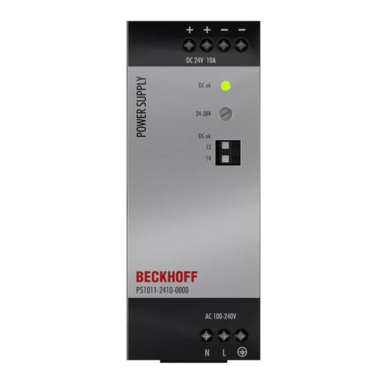
Technical data, mounting, wiring 3.11 Front side and operating elements Fig. 10: Front PS1011-2410-0000 Input terminals (screw terminals) Designation (A) Description Mains input N Mains input L Protective conductor, PE Output terminals (screw terminals) Designation (B) Description two identical positive poles, positive output... -
Page 21: Emc
EN 61000-6-3 Switching frequencies PFC converter 60kHz to 140kHz Input load and output voltage dependent Main converter 65kHz to 150kHz Output voltage and output load dependent PS1011-2410-0000 Version: 1.0... -
Page 22: Environment
Do not energize when condensation is present Tested in conjunction with DIN rails according to EN 60715 with a height of 15mm and a thickness of 1.3mm and standard mounting position. Fig. 11: Output current over ambient temperature; output current over installation altitude Version: 1.0 PS1011-2410-0000... -
Page 23: Protective Functions And Safety Features
At 230Vac, 50Hz, TN, TT / IT network max. 0.37mA / 0.94mA At 110Vac, 50Hz, TN, TT / IT network max. 0.54mA / 1.33mA At 132Vac, 60Hz, TN, TT / IT network max. 0.88mA / 2.18mA At 264Vac, 50Hz, TN, TT / IT network PS1011-2410-0000 Version: 1.0... -
Page 24: Dielectric Strength
(column D). We recommend connecting the DC-OK pins and the output pins when performing the test. Type test 2500Vac 3000Vac 1000Vac 500Vac Component test 5s 2500Vac 2500Vac 500Vac 500Vac Field test 2000Vac 2000Vac 500Vac 500Vac Setting the cut-off current > 15mA > 15mA > 20mA > 1mA Version: 1.0 PS1011-2410-0000... -
Page 25: Declaration Of Conformity And Approvals
Technical data, mounting, wiring 3.16 Declaration of conformity and approvals EU declaration of conformity UL Certificate: UL 61010-1/2-201 Applicable for US and Canada PS1011-2410-0000 Version: 1.0... -
Page 26: Dimensions And Weight
540g Plastic material of the Flame retardant polycarbonate (PC) - UL94-V0 housing Vicat softening temperature specified at 149°C according to ASTM D1525 Installation clearances See chapter on Safety instructions and installation requirements [} 9] Fig. 13: Front/side view PS2001-2410-0000 Version: 1.0 PS1011-2410-0000... -
Page 27: Application Notes
This power supply is stable and will not malfunction if a load is feeding back voltage to the power supply. It is irrelevant whether the power supply is switched on or off. The maximum permissible feed-back voltage is 35Vdc. The absorbing energy can be calculated according to the large built-in output capacitor indicated in the output data [} 13]. PS1011-2410-0000 Version: 1.0... -
Page 28: External Input Protection
The device is designed to supply all load types, including capacitive and inductive loads. If very large capacitors such as EDLCs (electric double-layer capacitors or "UltraCaps") with a capacitance of more than 2.0 F are connected to the output, the device charges the capacitor in hiccup mode if necessary (see Output [} 13] chapter). Version: 1.0 PS1011-2410-0000... -
Page 29: Charging Batteries
IP66 PK 9519 100, plastic PK 9519 100, plastic Input voltage 230Vac 230Vac Load 24V, 8A; (=80%) 24V, 10A; (=100%) Temperature inside 43.7°C 48,6°C the housing Temperature outside 24.9°C 24.9°C the housing Temperature 18.8K 23.7K increase PS1011-2410-0000 Version: 1.0... -
Page 30: Appendix
Appendix Appendix Documentation issue status Version Comment - First public issue - Addenda & corrections - Preliminary documentation for PS1011-2410-0000 Version: 1.0 PS1011-2410-0000... -
Page 31: Support And Service
Please contact your Beckhoff branch office or representative for local support and service on Beckhoff products! The addresses of Beckhoff's branch offices and representatives round the world can be found on her internet pages: https://www.beckhoff.com/english/beckhoff/world.htm You will also find further documentation for Beckhoff components there. - Page 33 More Information: www.becklhoff.com/ps1011-2410-0000 Beckhoff Automation GmbH & Co. KG Hülshorstweg 20 33415 Verl Germany Phone: +49 5246 9630 info@beckhoff.com www.beckhoff.com...
Need help?
Do you have a question about the PS1011-2410-0000 and is the answer not in the manual?
Questions and answers