
Related Manuals for Beckhoff CX2100-0004


Summary of Contents for Beckhoff CX2100-0004
- Page 1 Manual | EN CX2100-0004 Power supply unit for CX2020 and CX2030 2/9/2021 | Version: 1.2...
-
Page 3: Table Of Contents
2 For your safety............................ 8 Intended use ............................ 8 Staff qualification .......................... 8 Safety instructions .......................... 9 3 Transport and storage.......................... 10 4 Product overview............................. 11 Configuration of the CX2100-0004 power supply unit .............. 12 Name plate ............................ 13 5 Commissioning............................ 14 Mounting ............................ 14 5.1.1 Attaching the power supply unit.................. 14 5.1.2... - Page 4 Table of contents Version: 1.2 CX2100-0004...
-
Page 5: Notes On The Documentation
EP1590927, EP1789857, EP1456722, EP2137893, DE102015105702 with corresponding applications or registrations in various other countries. ® EtherCAT is registered trademark and patented technology, licensed by Beckhoff Automation GmbH, Germany Copyright © Beckhoff Automation GmbH & Co. KG, Germany. The reproduction, distribution and utilization of this document as well as the communication of its contents to others without express authorization are prohibited. -
Page 6: Representation And Structure Of Warnings
There is a potential hazard to the environment and equipment. Notes showing further information or tips: Tip or pointer This notice provides important information that will be of assistance in dealing with the product or software. There is no immediate danger to product, people or environment. Version: 1.2 CX2100-0004... -
Page 7: Related Documents
This documentation contains and describes material that is relevant for the power supply unit CX2100-0004. The power supply unit CX2100-0004 is part of a modular system and belongs to the CX2000 Embedded PC series. Further information on the devices of the CX2000 Embedded PC series can be found in the associated documentation. -
Page 8: For Your Safety
• Use of unauthorized replacement parts. Intended use The power supply unit CX2100-0004 is part of a modular control system and is intended for mounting on a DIN rail. The system is scalable, so that the basic PC modules, power supply units, system modules and extension modules can be assembled and installed in the control cabinet or terminal box as required. -
Page 9: Safety Instructions
• The sensitivity of a PC against malicious software increases with the number of installed and active software. • Uninstall or disable unnecessary software. Further information about the safe handling of networks and software can be found in the Beckhoff Information System: http://infosys.beckhoff.de... -
Page 10: Transport And Storage
Despite the robust design of the unit, the components are sensitive to strong vibrations and impacts. Protect the power supply unit during transport: • mechanical stress and • use the original packaging. Table 1: Dimensions and weights. Technical data CX2100-0004 Dimensions (W x H x D) 40 mm x 100 mm x 91 mm Weight 375 g Storage •... -
Page 11: Product Overview
Display The power supply unit CX2100-0004 has an FSTN LCD display with 2 x 16 characters, a selector switch and an Enter key. This allows internal status values as well as custom display parameters or menus, with and without input options, to be queried. -
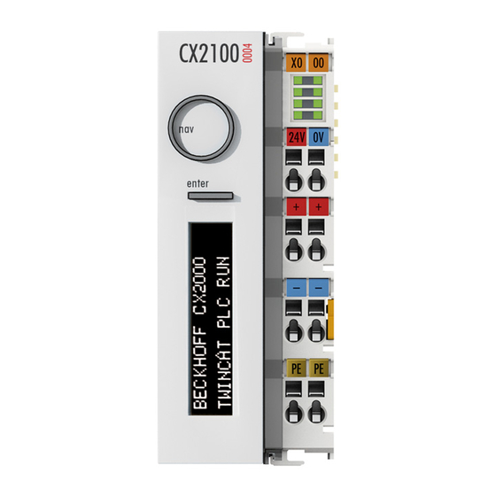
Page 12: Configuration Of The Cx2100-0004 Power Supply Unit
Product overview Configuration of the CX2100-0004 power supply unit Fig. 1: Configuration of the CX2100-0004 power supply unit. Table 3: Legend for the configuration. Component Description Multi-pole connection For connection to the basic CPU module on the right. Status display with 2 x 16 characters and backlight. -
Page 13: Name Plate
Product overview Name plate The CX2100-0004 power supply unit features a name plate on the left-hand side of the housing. Fig. 2: CX2100-0004 power supply unit name plate. Table 4: Legend for the name plate. Description UL approval with prescribed information on power supply, fuse, temperature and cable cross-sections. -
Page 14: Commissioning
Embedded PC CX2020 to demonstrate the procedure. 5.1.1 Attaching the power supply unit The power supply unit CX2100-0004 supplies power to Embedded PCs of the CX2000 series. The power supply unit and the Embedded PC are connected via the multi-pole connector. Proceed as follows: 1. - Page 15 3. Check that the bar clips are flush. ð The bar clips have been installed successfully, if they don't protrude and are level with the cooling fins of your modules. Once all modules are latched, the devices can be installed on the mounting rail. CX2100-0004 Version: 1.2...
-
Page 16: Note The Permissible Installation Positions
The CX2100-0004 power supply unit and the Embedded PC must be fastened horizontally to the mounting rail. The CX2100-0004 power supply unit does not support vertical or lying installation positions. -
Page 17: Attaching On Mounting Rail
Embedded PC has latched. 3. Then lock the latches again. ð You have installed the Embedded PC successfully. Double-check the correct installation and latching of the Embedded PC on the mounting rail. CX2100-0004 Version: 1.2... -
Page 18: Installing Passive Ethercat Terminals
The following diagram shows the permissible installation of a passive EtherCAT Terminal. The passive EtherCAT Terminal was not directly attached to the power supply unit. Fig. 5: Passive EtherCAT Terminals, permissible installation. The following diagram shows the invalid installation of a passive EtherCAT Terminal. Fig. 6: Passive EtherCAT Terminals, invalid installation. Version: 1.2 CX2100-0004... -
Page 19: Power Supply
Commissioning Power supply This chapter describes how to connect the power supply unit CX2100-0004. This documentation uses the Embedded PC CX2020 to demonstrate the procedure. 5.2.1 Connect Embedded PC NOTE Damage to the Embedded PCs The Embedded PCs may be damaged during wiring. -
Page 20: Table 7 Required Wire Cross-Sections And Strip Lengths
• Always disconnect the 24 V line. Devices connected to the Embedded PC, which have their own power supply (e.g. a Panel) must have the same potential for "PE" and "0 V" as the Embedded PC have (no potential difference). Version: 1.2 CX2100-0004... -
Page 21: Observe The Ul Requirements
Commissioning 5.2.2 Observe the UL requirements The Embedded PCs CX20xx and the power supply unit CX2100-0004 are UL508 certified. The corresponding UL label can be found on the type plate. Fig. 7: UL label on the CX20xx. The CX20xx Embedded PCs can thus be used in areas in which special UL requirements have to be met. -
Page 22: Configuration
0x34 0x54 0x74 0x35 0x55 0x75 0x36 0x56 0x76 0x37 0x57 0x77 0x38 0x58 0x78 0x39 0x59 0x79 0x3A 0x5A 0x7A 0x3B 0x5B 0x7B 0x3C < 0x5C 0x7C 0x3D 0x5D 0x7D 0x3E > 0x5E 0x7E 0x3F 0x5F Version: 1.2 CX2100-0004... -
Page 23: Displaying Texts
FB_CXSetTextDisplayUSB(FB) and the status values are read from the function block with FB_CXGetTextDisplayUSB(FB). A detailed documentation of the function blocks can be found in the TwinCAT software documentation. The two screenshots show the associated libraries for the function blocks. CX2100-0004 Version: 1.2... - Page 24 There are six tabs in the System Manager. These are briefly described below. The focus is thereby placed on the parameter that is relevant for the power supply unit Tab: General The general properties of the power supply unit are displayed here. Version: 1.2 CX2100-0004...
- Page 25 Here you can add a comment (e.g. regarding the system). Disabled Here you can deactivate the EtherCAT device. Tab: ESB Device The settings for the exchange of data between the power supply unit and the system are made and/or displayed here. CX2100-0004 Version: 1.2...
- Page 26 Device Handle Pointer to the device driver Data Exchange Cycle in which the communication takes place Port address for ADS access (7100 for the TwinCAT function block) Tab: ADS Commands The range for ADS communication is displayed here. Version: 1.2 CX2100-0004...
- Page 27 Configuration Tab: CoE Online CX2100-0004 Version: 1.2...
- Page 28 Such a list of parameters, the whole of the device-specific CoE directory, can become very extensive. The first entries of a Beckhoff EL3152 analog input terminal appear as follows in the TwinCAT System Manager: The index numbers are specified in the profile; they begin in EtherCAT with x1000, because the underlying entries do not have to be displayed.
- Page 29 Changes in this directory do not affect the later operation of the slave with TwinCAT. The xml files can be obtained from the Beckhoff website in the Download area. The TwinCAT system manager 2.11 can display both lists and marks this:...
- Page 30 Changes made to the local CoE directory of the EtherCAT slaves are lost with the old device in case of exchange. If a device is replaced with a new Beckhoff device, it will have the default set- tings. It is therefore advisable to link all changes in the CoE list of an EtherCAT slave with the Startup list of the slave, which is processed whenever the EtherCAT fieldbus is started.
- Page 31 Configuration Changed settings are stored fail-safe in Beckhoff devices. If the device is later exchanged, however, the settings that have been changed from the series standard are lost. The EtherCAT master can then load the changed CoE parameters into the new device at startup, if it is set up appropriately.
- Page 32 In the Boot state the slave firmware can be updated. The Boot state can only be reached via the Init state. In the Boot state mailbox communication is possible via the File-Access over EtherCAT (FoE) protocol, but no other mailbox communication and no process data communication is possible. Version: 1.2 CX2100-0004...
-
Page 33: Operating Principle Of The Button
PROGRAM MAIN bUp AT %I* : BOOL; bDown AT %I* : BOOL; bLeft AT %I* : BOOL; bRight AT %I* : BOOL; bEnter AT %I* : BOOL; bToggle AT %I* : BOOL; Taster : USINT; (* als Summenwert *) eNaviSwitchCx2 : E_CX2100_NaviSwitch; END_VAR CX2100-0004 Version: 1.2... - Page 34 The sum of the numerical values is used for the combined functions. In other words, UP (4) and RIGHT (32) would be 4 + 32 = 36. Values are: {UP (4), DOWN(8), LEFT(16), RIGHT(32) and ENTER(64)}. In this way only useful combinations are possible. Version: 1.2 CX2100-0004...
-
Page 35: Example Program
(* get navi switch *) eNaviSwitchCx2 := F_CXNaviSwitchUSB(nIn); (* prepare get display mode *) IF (eModeRead = eCX2100_DisplayNoActionRd) AND (eModeWrite = eCX2100_DisplayNoActionWr) THEN IF bReadCursorInfoReq THEN eModeRead := eCX2100_ReadCursorInfo; bExecuteRead := TRUE; ELSIF bReadBacklightReq THEN eModeRead := eCX2100_ReadBackLight; bExecuteRead := TRUE; CX2100-0004 Version: 1.2... - Page 36 bReadCursorInfoReq := TRUE; ELSIF bBlinkCursorOffReq THEN eModeWrite := eCX2100_CursorBlinkOff; bExecuteWrite := TRUE; bReadCursorInfoReq := TRUE; ELSIF bBacklightOnReq THEN eModeWrite := eCX2100_BackLightOn; bExecuteWrite := TRUE; bReadBacklightReq := TRUE; ELSIF bBacklightOffReq THEN eModeWrite := eCX2100_BackLightOff; bExecuteWrite := TRUE; bReadBacklightReq := TRUE; Version: 1.2 CX2100-0004...
- Page 37 nPort := 16#7100, eMode := eModeWrite, sLine1 := sLine1, sLine2 := sLine2, nCursorPosX := nCursorPosX, nCursorPosY := nCursorPosY, bBusy => bBusy, bError => bError, nErrorID => nErrorID ); IF NOT fbSetDisplayText.bBusy THEN fbSetDisplayText(bExecute := FALSE); bExecuteWrite := FALSE; eModeWrite := eCX2100_DisplayNoActionWr; END_IF END_IF CX2100-0004 Version: 1.2...
-
Page 38: Error Handling And Diagnostics
IF k_bus_state.10 = 1 THEN melde Fehler; (* K_bus Output Update ist aktiv *) END_IF IF k_bus_state.11 = 1 THEN melde Fehler; (* Watchdog Fehler *) END_IF IF k_bus_state.15 = 1 THEN melde Fehler; (* Bus ist asynchron *) END_IF END_CASE Version: 1.2 CX2100-0004... - Page 39 Error handling and diagnostics k_bus_request := TRUE; (* Rücksetzen des Busses, wenn Fehler beseitigt, dann startet der Klemmbus wieder *) ..In order for the controller and the registers to co-operate, they must be linked in the System Manager. CX2100-0004 Version: 1.2...
-
Page 40: Power Supply Terminal Leds In K-Bus Mode
Count how often the red LED K-bus ERR flashes, in order to determine the error code and the error argument. In the error argument the number of pulses shows the position of the last Bus Terminal before the error. Passive Bus Terminals, such as a power feed terminal, are not included in the count. Version: 1.2 CX2100-0004... -
Page 41: Table 9 K-Bus Err Led, Fault Description And Troubleshooting
LED after the error has been rectified. State variable In TwinCAT there is a State variable under the Bus Coupler for K-bus diagnostics. CX2100-0004 Version: 1.2... -
Page 42: Table 10 Description Of The State Variable Values
Bit 10 K-bus output update not yet complete. Bit 11 Watchdog. Bit 15 Acyclic K-bus function active (e.g. K-bus reset). If there is a K-bus error, this can be reset via the IOF_DeviceReset function block (in the TcIoFunctions.lib). Version: 1.2 CX2100-0004... -
Page 43: Power Supply Terminal Leds In E-Bus Mode
Up 24 V Power supply for terminal bus. The LED lights green if the power supply is correct. L / A E-bus not connected. E-bus connected / no data traffic. flashes E-bus connected / data traffic on the E-bus. CX2100-0004 Version: 1.2... -
Page 44: Decommissioning
2. Remove the wiring from the first terminal next to the power supply terminal. 3. Pull the orange strap to remove the first terminal after the power supply terminal by pulling it forward. ð In the next step the Embedded PC can be removed from the DIN rail and dismantled. Version: 1.2 CX2100-0004... -
Page 45: Disassembling The Power Supply Unit
Dismantle the Embedded PC as follows: 1. Release the DIN rail mounting by pushing the latches outwards with a screwdriver. 2. Pull the orange strap on the power supply unit and gently remove the device from the DIN rail. CX2100-0004 Version: 1.2... - Page 46 ð Once the bar clips have been removed successfully, the modules can be separated from each other. Disposal The device must be fully dismantled in order to dispose of it. Electronic components must be disposed of according to national electronic waste regulations. Version: 1.2 CX2100-0004...
-
Page 47: Technical Data
Technical data Technical data Table 11: Technical data, dimensions and weights. Technical data CX2100-0004 Dimensions (W x H x D) 40 mm x 100 mm x 91 mm Weight 375 g Table 12: Technical data, general data. Technical data CX2100-0004 Power supply 24 V DC (-15 %/+20 %) Dielectric strength 500 V (supply / internal electronics) -
Page 48: Appendix
All products of the Embedded PC family are CE, UL and EAC certified. Since the product family is continuously developed further, we are unable to provide a full listing here. The current list of certified products can be found at www.beckhoff.com. FCC Approvals for the United States of America... -
Page 49: Support And Service
Beckhoff's branch offices and representatives Please contact your Beckhoff branch office or representative for local support and service on Beckhoff products! The addresses of Beckhoff's branch offices and representatives round the world can be found on her internet pages: http://www.beckhoff.com You will also find further documentation for Beckhoff components there. - Page 50 Table 10 Description of the State variable values..................Table 11 Technical data, dimensions and weights..................Table 12 Technical data, general data....................... Table 13 Technical data, I/O terminals....................... Table 14 Technical data, environmental conditions..................Version: 1.2 CX2100-0004...
- Page 51 List of figures List of figures Fig. 1 Configuration of the CX2100-0004 power supply unit..............Fig. 2 CX2100-0004 power supply unit name plate................Fig. 3 Embedded PC CX2020, horizontal mounting position..............Fig. 4 Identifying a passive EtherCAT Terminal in TwinCAT..............
- Page 53 More Information: www.beckhoff.com/CX2100-0004 Beckhoff Automation GmbH & Co. KG Hülshorstweg 20 33415 Verl Germany Phone: +49 5246 9630 info@beckhoff.com www.beckhoff.com...
Need help?
Do you have a question about the CX2100-0004 and is the answer not in the manual?
Questions and answers