
Subscribe to Our Youtube Channel
Related Manuals for Beckhoff C9900-P208


Summary of Contents for Beckhoff C9900-P208
- Page 1 Installation and Operating instructions for C9900-P208/ -P209 Power Supply Unit Version: 1.3 Date: 2008-09-12...
-
Page 3: Table Of Contents
Operating Instructions UPS Software Components (only C9900-P209) Installation on the PC Help files Servicing Shutting down Disposal Troubleshooting Beckhoff Support & Service Beckhoff branches and partner companies Beckhoff Headquarters Beckhoff Support Beckhoff Service Assembly dimensions Wiring diagram Appendix Technical data Approvals... -
Page 4: General Notes
© This documentation is copyrighted. Any reproduction or third party use of this publication, whether in whole or in part, without the written permission of Beckhoff Automation GmbH, is forbidden. Description of safety symbols The following safety symbols are used in this operating manual. They are intended to alert the reader to the associated safety instructions. -
Page 5: Basic Safety Measures
Basic safety measures The power supply unit must only be used in conjunction with Beckhoff Industrial PCs! Note Switch off the power supply of the system during installation! During assembly, removal and electrical wiring of the power supply unit, Warning the power supply of the system must be switched off in order to prevent damage on the power supply unit and the Industrial PC. -
Page 6: Product Description
Product Description Product Description Appropriate Use The C9900-P208 and C9900-P209 power supply unit provide the power supply for Beckhoff Industrial PCs. The C9900-P209 power supply in conjunction with a C9900-U330 battery pack allows the construction of an uninterruptible power supply (UPS). -
Page 7: Electrical Data
For a detailed functional description please refer to section External wiring. Electrical data Input voltage: 22-30V DC/ 15A Power output: 250W (max.) Output voltages: + 5V + 12V + 3.3V - 5V 0.3A - 12V 0.5A + 5VSB 1.5A C9900-P208/ -P209... -
Page 8: Installation Instructions
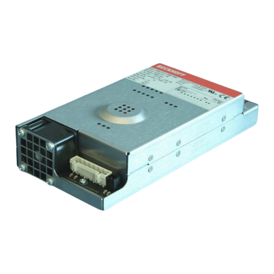
The power supply unit is installed at the prescribed position in the Industrial The supply connections for the power supply unit are located next to the fan (1). The electrical connections for the motherboard are on the opposite side (2). C9900-P208/ -209... -
Page 9: Connection With The Motherboard
+ 5V + 5V 5V/ 12V supply for drives Function Function + 12V + 12V + 5V + 5V POWER ON Function POWER-ON POWER-ON Function COM interface (RS 232) ATX 12V DC-Output Function Function + 12V + 12V C9900-P208/ -P209... -
Page 10: Connection With The Industrial Pc
Industrial PC. Due to different cable lengths, the harness is produced individually for each type of computer. The wiring diagram section shows the connection between the 7-pin power supply unit connector and the 3-pin and 5-pin pin strip at the PC case: C9900-P208/ -209... -
Page 11: External Wiring
Insert Fuse The power supply must be protected with 16 A. Pin assignment for Function connecting the power 24 V DC Power Supply supply and the battery pack Battery Pack (C9900-P209 only) C9900-P208/ -P209... -
Page 12: Configuration For Shutting Down The Pc
The maximum load is 2.0 A. • Once the PC has been de-energised via the UPS software, the UPS output is switched to 0 V. Any connected panel is thus switched off, and total discharge of the rechargeable battery is prevented. C9900-P208/ -209... -
Page 13: Installation Of The Supply Cables
4. Relieve the strain on the supply cable by fixing it in place with the cable clamp (part C) and fixing screws (part D) (see photograph below). Applying the strain relief Fix the upper part (part B) of the strain relief housing by snapping it onto the lower part. C9900-P208/ -P209... -
Page 14: Operating Instructions
The driver software comes with a detailed help function. System The help files can be called up either directly from the configuration register by clicking the Help button, or under via Start > Programs > Beckhoff > UPS software components. Servicing The power supply unit is maintenance-free. -
Page 15: Troubleshooting
Please contact your Beckhoff branch office or partner company for local support and service on Beckhoff products! The contact addresses for your country can be found in the list of Beckhoff branches and partner companies: www.beckhoff.com You will also find further documentation for Beckhoff components there. -
Page 16: Assembly Dimensions
Assembly dimensions Assembly dimensions Device dimensions and mounting points. Dimensional notation in mm. C9900-P208/ -209... -
Page 17: Wiring Diagram
Wiring diagram Wiring diagram Connection of the Battery Pack and UPS Output only in combination with Note C9900-P209 power supply. The circuit of PC_ON and Power-Status is symbolical. C9900-P208/ -P209... -
Page 18: Appendix
FCC: Canadian Notice FCC Approval for Canada This equipment does not exceed the Class A limits for radiated emissions as described in the Radio Interference Regulations of the Canadian Department of Communications. C9900-P208/ -209...
Need help?
Do you have a question about the C9900-P208 and is the answer not in the manual?
Questions and answers