
Subscribe to Our Youtube Channel
Related Manuals for Beckhoff CX2100-0904


Summary of Contents for Beckhoff CX2100-0904
- Page 1 Handbook CX2100-09x4 Powersupply with intergated UPS for CX20x0 Version: Date: 2015-11-20...
-
Page 3: Table Of Contents
Installation on the mounting rail ...................... 37 Mounting the module lock....................... 39 Mounting of passive terminals on the CX2100-0xx4 power supply .......... 41 5 Commissioning............................ 42 Configuration of the CX2100-0904 Integrated 24 V UPS .............. 42 UPS functions .......................... 45 5.2.1 BECKHOFF UPS Configuration dialog ................ 45 5.2.2... - Page 4 Table of contents 7 Decommissioning............................ 83 Disassembly and disposal ...................... 83 8 Appendix .............................. 85 Accessories ............................ 85 Certifications ........................... 86 Support and Service ........................ 87 Version: 1.3 CX2100-09x4...
-
Page 5: Foreword
EP0851348, US6167425 with corresponding applications or registrations in various other countries. ® EtherCAT is registered trademark and patented technology, licensed by Beckhoff Automation GmbH, Germany Copyright © Beckhoff Automation GmbH & Co. KG, Germany. The reproduction, distribution and utilization of this document as well as the communication of its contents to others without express authorization are prohibited. -
Page 6: Safety Instructions
All the components are supplied in particular hardware and software configurations appropriate for the application. Modifications to hardware or software configurations other than those described in the documentation are not permitted, and nullify the liability of Beckhoff Automation GmbH & Co. KG. Personnel qualification This description is only intended for trained specialists in control, automation and drive engineering who are familiar with the applicable national standards. -
Page 7: Documentation Issue Status
Foreword Documentation issue status Version Modifications Provisional version (original version) First version Smart battery added UL notes added CX2900-09x4 technical data and chapter Connection of Smart Battery extended CX2100-09x4 Version: 1.3... -
Page 8: Product Overview
Product overview Product overview Intended use The CX20x0 device series is a modular control system designed for DIN rail installation. The system is scalable, so that the required modules can be assembled and installed in the control cabinet or terminal box as required. -
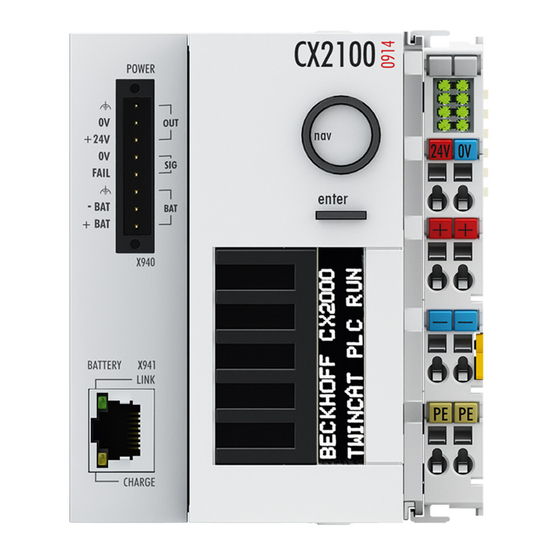
Page 9: Cx2100-0904 / Cx2100-0914 Product Overview
V power supply unit. The CX2100-0904 Power Supply Unit is passively cooled and is intended for operation in the extended temperature range of -25 to +50 °C. With the CX2100-0904 UPS Power Supply Unit the system can store data on the storage medium in case of a power failure and subsequently shut down properly. -
Page 10: Cx2100-0904 - Technical Data
Product overview CX2100-0904 - Technical data Technical data CX2100-0904 Power supply 24 V DC (-15 %/+20 %) Dielectric strength 500 V (supply / internal electronics) I/O connection E-bus (EtherCAT Terminals) or K-bus (Bus Terminals), automatic detection Power supply I/O terminals... -
Page 11: Cx2100-0914 - Technical Data
Operating/storage temperature -25...+60 °C/-25...+60 °C Relative humidity 95 % no condensation Vibration/shock resistance Conforms to EN 60068-2-6 / EN 60068-2-27 EMC immunity/emission Conforms to EN 61000-6-2 / EN 61000-6-4 Protection class IP 20 Approvals Further Information: www.beckhoff.de/CX2000 CX2100-09x4 Version: 1.3... -
Page 12: Cx2900-0192 - Technical Data
Operating/storage temperature -25...+60 °C/-25...+60 °C Relative humidity 95 % no condensation Vibration/shock resistance Conforms to EN 60068-2-6 / EN 60068-2-27 EMC immunity/emission Conforms to EN 61000-6-2 / EN 61000-6-4 Protection class IP 20 Approvals Further Information: www.beckhoff.de/CX2000 Version: 1.3 CX2100-09x4... -
Page 13: Display
Product overview Display 2.6.1 Structure of the display Structure of the display The display of the CX2100-00xx is an LCD. It has 2 x 16 characters. Each character has a resolution of 5 x 8 pixels. The character set has the designation SPLC780C-11 and is permanently set. The following illustration shows the character set with all available characters displayed inversely. -
Page 14: Displaying Texts
Product overview 2.6.2 Displaying texts Software connection for the display There is a possibility to set static texts via the System Manager. Alternatively there are two TwinCAT function blocks. Their names are FB_CXSetTextDisplayUSB(FB) and FB_CXGetTextDisplayUSB(FB). Parameters are written with FB_CXSetTextDisplayUSB(FB) and the status values are read from the function block with FB_CXGetTextDisplayUSB(FB). - Page 15 Product overview Availability of the function blocks These function blocks are available in the TwinCAT builds starting from version TC2.11 R3 Build 2240 Note TC3.1 Build 4015 With older versions an update is required for the use of the function blocks. Illustration of the display with the System Manager There are six tabs in the System Manager.
- Page 16 Product overview Name Name of the EtherCAT device Number of the EtherCAT device Type EtherCAT device type Comment Here you can add a comment (e.g. regarding the system). Disabled Here you can deactivate the EtherCAT device. Tab: ESB Device The settings for the exchange of data between the power supply unit and the system are made and/or displayed here.
- Page 17 Product overview ESB Id Serial numbers of the devices on the BUS Device Handle Pointer to the device driver Data Exchange Cycle in which the communication takes place Port address for ADS access (7100 for the TwinCAT function block) Tab: ADS Commands The range for ADS communication is displayed here.
- Page 18 Product overview Tab: CoE Online Version: 1.3 CX2100-09x4...
- Page 19 Such a list of parameters, the whole of the device-specific CoE directory, can become very extensive. The first entries of a Beckhoff EL3152 analog input terminal appear as follows in the TwinCAT System Manager: The index numbers are specified in the profile; they begin in EtherCAT with x1000, because the underlying entries do not have to be displayed.
- Page 20 Changes in this directory do not affect the later operation of the slave with TwinCAT. The xml files can be obtained from the Beckhoff website in the Download area. The TwinCAT system manager 2.11 can display both lists and marks this:...
- Page 21 Start-up list Changes made to the local CoE directory of the EtherCAT slaves are lost with the old de- vice in case of exchange. If a device is replaced with a new Beckhoff device, it will have the Note default settings. It is therefore advisable to link all changes in the CoE list of an EtherCAT slave with the Startup list of the slave, which is processed whenever the EtherCAT fieldbus is started.
- Page 22 Product overview Changed settings are stored fail-safe in Beckhoff devices. If the device is later exchanged, however, the settings that have been changed from the series standard are lost. The EtherCAT master can then load the changed CoE parameters into the new device at startup, if it is set up appropriately.
- Page 23 Product overview Init After switch-on the EtherCAT slave in the Init state. No mailbox or process data communication is possible. The EtherCAT master initializes sync manager channels 0 and 1 for mailbox communication. Pre-Operational (Pre-Op) During the transition from Init to Pre-Op, the EtherCAT slave checks whether the mailbox has been correctly initialized.
-
Page 24: Button
Product overview Button 2.7.1 Operating principle of the button The CX1100-0xx4 power supply units all have four navigation switches and an Enter button. The buttons can therefore be used to input five basic states Button Value Button Value RIGHT DOWN ENTER / SELECT LEFT Combined inputs, such as UP + RIGHT or UP + RIGHT + ENTER can also be entered. - Page 25 Product overview (* get navi switch *) eNaviSwitchCx2 := F_CXNaviSwitchUSB(Taster); The button can be accessed from the PLC program through the button variable. A simple CASE statement can then be used to evaluate the switch, and the desired function can be initiated, e.g.: CASE Taster OF 4 : ACTION := UP;...
-
Page 26: Example Program
Product overview Example Program The following PLC program shows by way of an example how the three function blocks are used for the power supply unit. PROGRAM MAIN nCounter AT %Q*: USINT; (* navi switch *) bUp AT %I* : BOOL; bDown AT %I* : BOOL;... - Page 27 Product overview ELSIF bReadLine1Req THEN eModeRead := eCX2100_ReadLine1; bExecuteRead := TRUE; ELSIF bReadLine2Req THEN eModeRead := eCX2100_ReadLine2; bExecuteRead := TRUE; ELSIF bReadLinesReq THEN eModeRead := eCX2100_ReadLines; bExecuteRead := TRUE; END_IF END_IF (* get display *) IF (eModeRead <> eCX2100_DisplayNoActionRd) AND (eModeWrite = eCX2100_DisplayNoActionWr) THEN fbGetDisplayText( bExecute := bExecuteRead, sNetID := '',...
- Page 28 Product overview ELSIF bClearDisplayReq THEN eModeWrite := eCX2100_ClearDisplay; bExecuteWrite := TRUE; bReadLinesReq := TRUE; ELSIF bWriteLine1Req THEN eModeWrite := eCX2100_WriteLine1; bExecuteWrite := TRUE; bReadLine1Req := TRUE; ELSIF bWriteLine2Req THEN eModeWrite := eCX2100_WriteLine2; bExecuteWrite := TRUE; bReadLine2Req := TRUE; ELSIF bWriteLinesReq THEN eModeWrite := eCX2100_WriteLines; bExecuteWrite := TRUE;...
-
Page 29: Transport
5. Check the contents for visible shipping damage. 6. If you notice any shipping damage or inconsistencies between the contents and your order, you should notify Beckhoff Service. Danger of damage to the device! During transport in cold conditions, or if the device is subjected to extreme temperature dif- ferences, condensation on and inside the device must be avoided. -
Page 30: Mounting And Wiring
Mounting and wiring Mounting and wiring Mechanical installation 4.1.1 Dimensions The following drawings show the dimensions of the CX2100-0904 UPS Power Supply Unit. Version: 1.3 CX2100-09x4... - Page 31 Mounting and wiring The following drawings show the dimensions of the CX2100-0914 UPS Power Supply Unit. CX2100-09x4 Version: 1.3...
-
Page 32: Wiring
4.2.1 Power supply This power supply unit is equipped with an I/O interface, which permits connection of the Beckhoff Bus Terminals. The power is supplied via the upper spring-loaded terminals labelled “24V” and “0V”. The supply voltage supplies the CX system ant the terminal Bus and Bus Terminal with a voltage of 24 V DC (-15%/+20 %). - Page 33 Mounting and wiring CX2100-0914 Power Supply: UL requirements Compliance of the UL requirements For the compliance of the UL requirements the CX-Controllers should only be supplied by a 24 VDC supply voltage, supplied by an isolating source and protected by means of a fuse DANGER (in accordance with UL248), rated maximum 4 Amp.by a 24 VDC power source, that has to satisfy NEC class 2.
- Page 34 Mounting and wiring The terminals are implemented in spring force technology. Connect the cables as follows: 1. Open a spring-loaded terminal by slightly pushing with a screwdriver or a rod into the square opening above the terminal. 2. The wire can now be inserted into the round terminal opening without any force. 3.
-
Page 35: Connection Of Cx2900-0192 Smart Battery
Mounting and wiring 4.2.2 Connection of CX2900-0192 Smart Battery The CX2100-0914 UPS Power Supply Unit stores its charge in a CX2900-0192 Smart Battery. This is to capable of supporting the CX-system for longer periods in case of a power failure. In addition a further device, e.g. - Page 36 Mounting and wiring Connections: X940 power connection: OUT: • Earth • 0V • +24V A control panel or a monitor can be connected here. The Port supplies external devices with max. 48 W. Use a corresponding fuse to secure the connected devices. SIG: •...
-
Page 37: Installation On The Mounting Rail
Mounting and wiring Installation on the mounting rail Snapping onto the mounting rail The CX20x0 can simply be snapped onto the mounting rail. The bar clips are inserted on the top side and underside Then simply position the block on the mounting rail and push it slightly until it engages on the right-hand side. - Page 38 Mounting and wiring Incorrect installation positions The CX20x0 system must not be operated vertically on the DIN rail. A vertical position would lead to insufficient CPU ventilation, since the ventilation openings are located on the top and bottom of the housing. Installation of the system on its side would also lead to inadequate ventilation.
-
Page 39: Mounting The Module Lock
Mounting and wiring Mounting the module lock Mounting the lock The CX20x0 controller system is fully modular, i.e. all system interfaces of the system are field-configurable. As a rule the latching of the modules to each other is sufficiently strong. However, it is possible for the controller and its modules to be exposed to vibrations, shocks or impacts. - Page 40 Mounting and wiring Underside Top side Once the bar clips have been raised they can be pulled out. Subsequently, the system interfaces can be separated again. Version: 1.3 CX2100-09x4...
-
Page 41: Mounting Of Passive Terminals On The Cx2100-0Xx4 Power Supply
Mounting and wiring Mounting of passive terminals on the CX2100-0xx4 power supply Note on the mounting of passive terminals EtherCAT Bus Terminals (ELxxxx/ESxxxx) that do not actively participate in data exchange within the Bus Terminal block are called passive terminals. These terminals can be recog- Note nised by their lack of power consumption from the E-Bus. -
Page 42: Commissioning
Control Panel -> Regional Settings for the UI dialogs. If a language is not supported by the Beckhoff UPS dialog, the dialog appears in US English. 1. Open the BECKHOFF UPS configuration dialog, and then go to Select.. - Page 43 Commissioning 2. From the list of the manufacturers select Beckhoff and as the model Beckhoff CX2100-09xx. 3. Close the dialog with Finish and confirm with Apply. This will cause the UPS service to adopt the settings and start the UPS service.
- Page 44 Commissioning system is only initiated once the alarm has been triggered. This option should be selected in order to protect the battery. Set the “Battery time” to 2 minutes, for example. The permitted values lie between 0 and 720 minutes. The system will be shut down once this time has elapsed after a power failure. This option corresponds to the same option that can be set in the standard UPS dialog, with the difference that the shorter times of 0 and 1 minute can also be set.
-
Page 45: Ups Functions
Following installation under Win2K/XP/XPe/WES 7 the UPS configuration dialog will be found as an additional tab under Control Panel -> Power Options. Under NT4.0 UPS configuration dialog can be called via the shortcut under Control Panel -> BECKHOFF UPS Configuration. - Page 46 Control Panel -> Regional Settings for the UI dialogs. If a language is not supported by the Beckhoff UPS dialog, the dialog appears in US English. Power-fail counter: From UPS software version >= 3.0.0.6. The counter is set to zero on starting the UPS service and counts the number of power failures detected by the UPS service.
- Page 47 Commissioning The correct ISA/PCI address must be configured for the CP903x UPS: Search: If you have one of the integrated 24V UPS devices on the CP903x card and want to configure it for UPS service you can use the Search button to find the correct address of the CP903x ISA or PCI card. CX2100-09x4 Version: 1.3...
- Page 48 UPS info. dialog The detailed UPS information is displayed in this dialog. UPS fan status: Only available with Beckhoff P24Vxxxx with firmware version >= 45.1.I. The nominal speed of the fan is ~3000 RPM or ~10000 RPM. UPS fan speed: Only available with Beckhoff P24Vxxxx with firmware version >= 45.1.I.
- Page 49 Commissioning CX2100-09x4 Version: 1.3...
- Page 50 Battery change 0 - 480 60 (5 years) Only for the Beckhoff P24Vxxxx UPS from UPS interval service [months] and checkbox software v3.0.0.8 or higher. An interval service...
- Page 51 Available from UPS software v3.0.0.8 and higher. Restores the factory settings (default values). Saves the settings and closes the dialog. Please do not forget to confirm the settings in the Beckhoff UPS Configuration dialog. Cancel Discards all editable changes. *) Example values 5.2.1.5...
- Page 52 Commissioning Setting/command Area Default value Description UPS soft- ware ver- sion Activate all notifications Deactivated Deactivated This option can be used to instruct or activated (checkbox not the operating system to send checked) messages to the user in case of Power failure.
- Page 53 Commissioning Setting/command Area Default value Description UPS soft- ware ver- sion Combo box (task list) Task Sched- "UPS System Please do not forget to set the user v3.0.0.10 uler tasks Shutdown name and his password during the Program" configuration of the shutdown task. The shutdown task is managed by the Windows Task Scheduler and can only be executed in a certain...
- Page 54 Factory settings All settings are reset to their default values. Saves the settings and closes the dialog. Please do not forget to confirm the settings in the Beckhoff UPS Configuration dialog. Cancel Discards all editable changes and closes the dialog.
- Page 55 Commissioning The table provides a brief summary of the various delay times for a few UPS models. UPS model Beckhoff P24Vxxxx Beckhoff 24V APC Back-UPS APC Smart-UPS UPS on the Pro 280 CP903x card Available delay times in 20, 30*, 45*, 60, 90, 180,...
- Page 56 UPS protection is deactivated after a configurable delay time, in order to enable the PC and the UPS to be switched off (e.g. via the main switch). This option is only supported by Beckhoff P24Vxxxx UPS and UPS firmware version >= 33.1.I. In other models this option is deactivated.
- Page 57 Commissioning 5.2.1.6 About dialog This dialog displays the version information for the UPS software components. 5.2.1.7 Help dialog Calling the help dialog: CX2100-09x4 Version: 1.3...
-
Page 58: System Behavior: Beckhoff Miniport Driver For The Windows Ups Service
Commissioning 5.2.2 System behavior: Beckhoff miniport driver for the Windows UPS service Definitions: Short power failure: tBatt <tCA Long power failure: tBatt >=tCA Version: 1.3 CX2100-09x4... - Page 59 If tBatt >= tCA the UPS service irrevocably starts shutting down the system. Maximum time on battery voltage Configurable in minutes via the Beckhoff before critical alarm. Once this time has UPS configuration dialog. elapsed the UPS service irrevocably If tCA = 0 the UPS service immediately starts shutting down the system.
- Page 60 Commissioning Value Description Features tBoot Time required by the operating system Variable, depends on the number of during the boot process until the UPS applications and services that have to be service is started. started. Long power failure during operation (tBatt >= tCA) The UPS service has been started and is active.
- Page 61 Commissioning Power failure during the boot process The UPS service is not yet active at this time. The UPS automatically switches to battery operation, thus bridging the power failure. The PC is booted up in battery mode. During a prolonged power failure the UPS service takes over control after the start and starts shutting down the system.
-
Page 62: Ups Information In The Windows Registry
UPS information in the Windows Registry The UPS service communicates with the Beckhoff UPS driver via the Windows Registry. You can access this information in read mode. In order to configure the UPS (write), please use the "Beckhoff UPS Configuration dialog". - Page 63 BatteryReplaceDate REG_SZ Date of the last battery change. The date can "" be set with a command in the Beckhoff UPS Configuration dialog -> Device Configuration…. Implemented in the UPS software v3.0.0.8 and higher.
- Page 64 Commissioning Configuration settings KEY_LOCAL_MACHINE\SYSTEM\CurrentControlSet\Services\UPS\Config The keys below it are used by the UPS service for the configuration of the UPS: Version: 1.3 CX2100-09x4...
- Page 65 • other values are not permissible; TaskName REG_SZ Name of the Task Scheduler shutdown task. "" The Beckhoff UPS Configuration dialog generates a shutdown task with the name: "UPS System Shutdown Program". TaskFolder REG_SZ Path to the folder containing the Task ""...
- Page 66 Commissioning Name Type Description Default value TurnUPSOffEnable REG_DWORD Activates/deactivates the switching-off of the UPS output voltage after the shutdown: • 0 := deactivated; • 1 := activated (switches off); • other values are not permissible; TurnUPSOffWait REG_DWORD Maximum delay time in seconds for switching off the UPS output voltage after initiating the Windows shutdown.
-
Page 67: Twincat Plc Ups Interface
Requirements under Windows CE: • Beckhoff CE devices with 24 V UPS service are delivered with a special Beckhoff Battery Driver for Windows CE. The driver is included in the standard CE Image. No further configuration settings are required. - Page 68 Commissioning bValid: If this output is set the data in the ST_UPSStatus structure are valid (no error occurs at the last read cycle). bError: This output is set if an error occurs by execution of the function. nErrId: Supplies the Ads error number or a command specific error code (table) when bError output is set. stStatus: Structure with the status information of UPS.
-
Page 69: Type St_Upsstatus
Commissioning Requirements Development environ- Target system type UPS hardware PLC libraries to include ment TwinCAT v2.8.0, Build > PC (i386) • Beckhoff P24Vxxxx TcIoFunctions.Lib 745 TwinCAT v2.9.0, USV; ( Standard.Lib; Build > 945 TcBase.Lib; • Integrated Beckhoff TcSystem.Lib; Industrial PC 24V TcUtilities.Lib are included... - Page 70 Commissioning Status info Beckhoff Beckhoff 24V APC Back-UPS APC Smart- Description P24Vxxxx UPS UPS con- Pro 280 UPS 420 nected to CP903x ISA or PCI card Vendor Reports the UPS vendor name as displayable string. Model Reports the UPS model...
- Page 71 Commissioning Status info Beckhoff Beckhoff 24V APC Back-UPS APC Smart- Description P24Vxxxx UPS UPS con- Pro 280 UPS 420 nected to CP903x ISA or PCI card eBatteryStatus • • The current BatteryU BatteryU status of the nknownS nknownS UPS batteries.
- Page 72 Commissioning Status info Beckhoff Beckhoff 24V APC Back-UPS APC Smart- Description P24Vxxxx UPS UPS con- Pro 280 UPS 420 nected to CP903x ISA or PCI card dwChargeFlag • No • High (bit None None Battery charge battery 0 set) if status flags.
-
Page 73: Type E_Batterystatus
Commissioning Requirements Development environ- Target system type UPS hardware PLC libraries to include ment TwinCAT v2.8.0, Build > PC (i386) • Beckhoff P24Vxxxx TcIoFunctions.Lib 745 TwinCAT v2.9.0, USV; ( Standard.Lib; Build > 945 TcBase.Lib; • Integrated Beckhoff TcSystem.Lib; Industrial PC 24V TcUtilities.Lib are included... -
Page 74: Type E_Upspowerstatus
END_TYPE Requirements Development environ- Target system type UPS hardware PLC libraries to include ment TwinCAT v2.8.0, Build > PC (i386) • Beckhoff P24Vxxxx TcIoFunctions.Lib 745 TwinCAT v2.9.0, USV; ( Standard.Lib; Build > 945 TcBase.Lib; • Integrated Beckhoff TcSystem.Lib; Industrial PC 24V TcUtilities.Lib are included... -
Page 75: Battery Driver For Windows Ce
Battery driver for Windows CE Beckhoff Industrial PCs with Windows CE and 24 V UPS support are supplied with a special Beckhoff battery driver for Windows CE. In these devices the driver is included in the standard CE image. No further configuration settings are required. -
Page 76: System Behavior: Battery Driver For Windows Ce
// Add any extra information after the BatteryChemistry member. } SYSTEM_POWER_STATUS_EX2, *PSYSTEM_POWER_STATUS_EX2, *LPSYSTEM_POWER_STATUS_EX2; Please note that not all parameters are supported by the Beckhoff UPS. The main member variables include: ACLineStatus: Status of the external power supply. BatteryLifePercent: Battery charge status in percent. -
Page 77: Error Handling And Diagnostics
Error handling and diagnostics Error handling and diagnostics Diagnostics in the PLC program For the analysis of the terminal bus (K-bus) the State register can be accessed via TwinCAT from a PLC program. The error analysis is presented as an example below. A signal/variable is essentially required for the error analysis: •... -
Page 78: Leds Of The Power Supply In K-Bus Mode
Error handling and diagnostics LEDs of the power supply in K-bus mode After switching on, the power supply immediately checks the connected Bus Terminal configuration. Error- free start-up is signalled by the red "I/O ERR” LED being extinguished. If the “I/O ERR” LED blinks, an error in the area of the terminals is indicated. - Page 79 Error handling and diagnostics LEDs for K-bus diagnostics Error code Error code argu- Description Remedy ment Persistent, continuous EMC problems - Check power supply for flashing overvoltage or undervoltage peaks - Implement EMC measures If a K-Bus error is present, it can be localized by a restart of the power supply (by switching it off and then on again)
- Page 80 Error handling and diagnostics K-bus state The K-bus status is saved in the state byte (see fig. K-bus interface “1”). If the value is 0 the K-bus is operating synchronously and without errors. If the value is <> ”0” there may be a fault, or it may only be an indication that the K-bus cycle is longer than the task, in which case it would no longer by synchronous with the task.
-
Page 81: Leds Of The Power Supply In E-Bus Mode
Error handling and diagnostics LEDs of the power supply in E-bus mode After switching on, the power supply immediately checks the connected Bus Terminal configuration. In the E- Bus mode the “L/A” led lights up. It starts blinking when there is traffic on the bus. Display Meaning Us 24 V... -
Page 82: Faults
6. Any components / software used The quickest response will come from support / service in your country. Therefore please contact your regional contact. For details please refer to our website at www.beckhoff.de or ask your distribution partner. Version: 1.3... -
Page 83: Decommissioning
Decommissioning Decommissioning Disassembly and disposal The disassembly of a CX20x0 hardware configuration with system interfaces takes place in 3 steps 1. Switching off and disconnecting the power supply Before a CX20x0 system can be dismantled, the system should be switched off, and the power supply should be disconnected. - Page 84 Decommissioning After pulling on the terminal release of the power supply unit (see arrow) the block can be carefully removed from the DIN rail. Disposal The device must be fully dismantled in order to dispose of it. Electronic parts must be disposed of in accordance with national electronics scrap regulations. Version: 1.3 CX2100-09x4...
-
Page 85: Appendix
Appendix Appendix Accessories Table 1: CFast cards with first order (instead of 4 GB CFast card) Order number Description CX2900-0029 8 GB CFast card, SLC Flash, extended temperature range, instead of 4 GB CFast card CX2900-0031 16 GB CFast card, SLC Flash, extended temperature range, instead of 4 GB CFast card CX2900-0033 16 GB CFast card, SLC Flash, extended temperature range, instead of 8 GB... -
Page 86: Certifications
All products of the Embedded PC family are CE, UL and GOST-R certified. Since the product family is continuously developed further, we are unable to provide a full listing here. The current list of certified products can be found at www.beckhoff.com. FCC Approvals for the United States of America... -
Page 87: Support And Service
Beckhoff's branch offices and representatives Please contact your Beckhoff branch office or representative for local support and service on Beckhoff products! The addresses of Beckhoff's branch offices and representatives round the world can be found on her internet pages: http://www.beckhoff.com You will also find further documentation for Beckhoff components there.
Need help?
Do you have a question about the CX2100-0904 and is the answer not in the manual?
Questions and answers