
Related Manuals for Beckhoff CU8130-0120


Summary of Contents for Beckhoff CU8130-0120
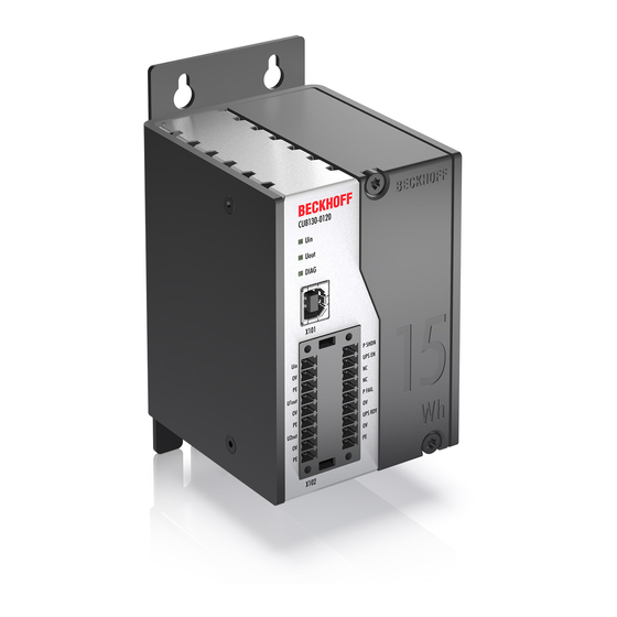
- Page 1 Manual | EN CU8130-0120 Uninterruptible Power Supply (Battery-backed) 1/14/2021 | Version: 1.0...
-
Page 3: Table Of Contents
Alarm configuration dialog .................... 33 Configuring the UPS ........................ 36 TwinCAT interface ........................... 38 7.5.1 FB_GetUPSStatus...................... 38 7.5.2 ST_UPSStatus......................... 40 7.5.3 E_BatteryStatus....................... 44 7.5.4 E_UpsCommStatus ...................... 44 7.5.5 E_UpsPowerStatus...................... 45 8 Error handling and diagnostics...................... 46 9 Care and maintenance .......................... 47 CU8130-0120 Version: 1.0... - Page 4 Table of contents Replacing the battery module ...................... 47 Cleaning ............................ 48 10 Decommissioning............................ 49 10.1 Dismantling the UPS ........................ 49 10.2 Disposal ............................ 50 11 Technical data............................ 51 12 Appendix .............................. 52 12.1 Accessories ............................. 52 12.2 Support and Service ........................ 53 Version: 1.0 CU8130-0120...
-
Page 5: Notes On The Documentation
EP1590927, EP1789857, EP1456722, EP2137893, DE102015105702 with corresponding applications or registrations in various other countries. ® EtherCAT is a registered trademark and patented technology, licensed by Beckhoff Automation GmbH, Germany Copyright © Beckhoff Automation GmbH & Co. KG, Germany. The reproduction, distribution and utilization of this document as well as the communication of its contents to others without express authorization are prohibited. -
Page 6: Representation And Structure Of Warnings
There is a potential hazard to the environment and equipment. Notes showing further information or tips: This notice provides important information that will be of assistance in dealing with the product or software. There is no immediate danger to product, people or environment. Version: 1.0 CU8130-0120... -
Page 7: Documentation Issue Status
Notes on the documentation Documentation issue status Version Modifications First version CU8130-0120 Version: 1.0... -
Page 8: Safety
Intended use The CU8130-0120 UPS is intended for mounting on a DIN rail in an industrial control cabinet or terminal box. Alternatively, the UPS can be equipped with a mounting plate and mounted on the rear panel of the control cabinet. - Page 9 • During firefighting wear self-contained respiratory protective equipment and protective clothing. • Air the room after you have extinguished the UPS. Safety labels on the UPS The following safety labels are attached to the name plate of the UPS: CU8130-0120 Version: 1.0...
-
Page 10: Transport And Storage
Therefore, during transport please protect your device from: • mechanical stress and • use the original packaging. Table 1: Dimensions and weight CU8130-0120 Dimensions (W x H x D) 60 mm x 100 mm x 90 mm Weight approx. 800 g... -
Page 11: Product Overview
In the case of a fault or the failure of the 24 V DC input voltage, the UPS takes over the supply of power to the connected devices with a controlled and buffered 24 V DC output voltage. All Beckhoff components or components from third-parties, especially Industrial PCs, Embedded PCs, Panels and Panel PCs, can be equipped with the CU81xx UPS series. -
Page 12: Name Plate
Maximum power consumption and power output of the UPS. UPS capacity. Hardware and software version. Power supply 24 V DC. CE approval. Machine-readable information in the form of a Data Matrix Code (DMC, code scheme ECC200) that you can use for better identification and management. Version: 1.0 CU8130-0120... -
Page 13: Block Diagram
At the same time, an overvoltage warning is output. Therefore, less than 24 V and more than 28.8 V can never be present at the UPS output. The complete control of the UPS is handled by the central UPS controller, which orchestrates the interaction of all other microcontrollers (UPS-OCT communication, charge controller). CU8130-0120 Version: 1.0... -
Page 14: Holding Times
Discharge current [A] Time to switch-off [s] Usable energy [Wh] 3750 12.50 1900 12.67 1215 12.15 12.00 10.83 9.00 7.47 4.67 1.02 Fig. 4: Hold time without temperature and ageing effects. Fig. 5: Usable energy without temperature and ageing effects. Version: 1.0 CU8130-0120... -
Page 15: Interfaces
USB 2.0 interface (X101) The USB interface is a communication interface between the UPS and Industrial PC. Die USB interface can be used especially by devices without UPS-OCT. These include, for example, older Beckhoff Industrial PCs but also components supplied by third-party providers. -
Page 16: Power Supply (X102)
+24 V DC output for power-fail-signal. This output is switched to 24 V if the power supply fails or if P SHDN is activated. This output can be connected with the PC_ON input on a Beckhoff Industrial PC or any PLC input. -
Page 17: Commissioning
Commissioning Commissioning Assembly Fig. 8: CU8130-0120 dimensions. Fig. 9: CU8130-0120 with mounting plate (optional), dimensions. CU8130-0120 Version: 1.0... -
Page 18: Fastening To The Din Rail
UPS can be attached on the upper edge of the DIN rail. 4. Attach the UPS to the upper edge of the DIN rail. ð You have successfully mounted the UPS. Check again that the mounting is correct and that the UPS is engaged on the DIN rail. Version: 1.0 CU8130-0120... -
Page 19: Installing The Mounting Plate (Optional)
1. Loosen the six M4 screws and remove the DIN rail adapter. 2. Loosen the M3 screws and remove the grounding springs from the UPS. 3. Fasten the mounting plate to the rear panel of the UPS with four M4 screws. CU8130-0120 Version: 1.0... -
Page 20: Power Supply
Connect the devices to be supported to the U1out and U2out outputs. If the external 24 V DC input voltage is lost, the UPS takes over the supply of the devices connected to it thanks to its regulated and buffered 24 V DC output voltage. Use the two 9-pin connectors with push-in connection to wire the CU8130-0120 UPS. -
Page 21: Communication
6.3.1 Connection via UPS-OCT A special feature of the Beckhoff CU8130-0120 UPS is OCT (One Cable Technology) as a communication technology between UPS and Industrial PC. The two connection cables (+24 V, 0 V) between the Industrial PC and the UPS are used to supply power to the Industrial PC and for bidirectional, modulated data transmission. -
Page 22: Connecting Additional Devices
If you are supporting an additional device, the interfaces U1out and U2out combined must not exceed the maximum output current of the UPS. Fig. 12: Connection example when using the second USP output (U2out) for an additional Control Panel. Version: 1.0 CU8130-0120... -
Page 23: Connection Via Usb
UPS configured when communicating via USB. Fig. 13: Example of a connection via USB with a CU8130-0120 UPS and a CX5240 Embedded PC. The USB interface conforms to the USB 2.0 standard. The cable length is limited to 5 m. -
Page 24: Connection Via Digital I/O
P FAIL In the case of Beckhoff Industrial PCs, the P-FAIL output of the UPS can be connected to the PC_ON input of an Industrial PC. In the event of a power failure, the P-FAIL output is set to 24 V. 24 V are thus applied to the PC_ON input of the Industrial PC and the Industrial PC is shut down properly. -
Page 25: Charging The Ups
UPS is continuously charged. This step shows how you can charge the UPS in order to commission or store the UPS in a charged state. For this you need a 24 V power supply unit and the Beckhoff UPS. Proceed as follows: 1. -
Page 26: Configuration
This chapter shows you how to install the Beckhoff UPS software on an Industrial PC or a non Beckhoff PC. If an older version of the UPS software is already installed, uninstall it first, since it may not be possible to update all files. -
Page 27: System Behavior
Configuration System behavior The settings under Alarm configuration influence the system behavior of the Beckhoff Miniport driver and affect how long the UPS supports the devices connected to it, when notifications or the critical alarm are issued. Short power failure: t <t... - Page 28 Maximum time on battery voltage before critical Configurable in minutes (or in seconds starting alarm. Once this time has elapsed the UPS from Windows 7 and higher) via the Beckhoff service irrevocably starts shutting down the UPS configuration dialog. system.
- Page 29 (e.g. XP): For systems without soft power-off functionality • With Beckhoff P24Vxxxx UPS: tDlg = 0, the the dialog should be visible at least for a short UPS switches off the outputs and the IPC time before the UPS switches off the IPC.
-
Page 30: Ups Configuration Dialogs
Power fail counter: From UPS software version >= 3.0.0.6. The counter is reset at UPS service start and counts the detected power fails. Details: Shows current configured UPS model and manufacturer name. Manufacturer name "(None)" means UPS service not configured and deactivated. Version: 1.0 CU8130-0120... -
Page 31: Device Configuration Dialog
Setting or Value range Default value Description function Battery Type C9900-U330, C9900-U330 Configures the used Beckhoff battery pack type. (combo box) C9900-U332, User-Defined Battery Type 0..99 Available only if "User-Defined" battery type is selected. (edit field) The setting is necessary, for instance, to be able to calculate the remaining charge available under battery operation. - Page 32 Defaults type setting is: C9900-U330. Please check your real battery type configuration. Saves all settings and closes the dialog. Don't forgett to apply the changes at the Beckhoff UPS Configuration dialog too. Cancel Discards all editable changes. *) Example value.
-
Page 33: Alarm Configuration Dialog
The user have to select one of the tasks. The default task (if existing) with the name: "UPS System Shutdown Program" is selected automatically it the task is configured for the first time. CU8130-0120 Version: 1.0... - Page 34 Finally, turn off the UPS Disabled or Enabled If you have selected this option, the UPS will switch enabled the outputs off after the PC has been shut down, in (checkbox is order to save the battery charge (Standard: selected) Selected). Version: 1.0 CU8130-0120...
- Page 35 Beckhoff UPS Configuration dialog too. Cancel Discards all editable changes and closes the dialog. Delay times for switching off the UPS in seconds: • Beckhoff USB UPS: 20, 30, 45, 60, 120, 180, 300, 600 CU8130-0120 Version: 1.0...
-
Page 36: Configuring The Ups
Configuration Configuring the UPS This step shows how to configure the UPS in the Beckhoff UPS software. Two of the most important settings that affect the behavior of the UPS in the event of a power failure are: • Max. time on battery before critical alarm •... - Page 37 Industrial PC is shutting down. As soon as the critical alarm is triggered, the set countdown of 180 seconds is started. The shutdown of the Industrial PC must be successfully completed within this time (180 seconds), since the outputs of the UPS are switched off directly after the 180 seconds have elapsed. CU8130-0120 Version: 1.0...
-
Page 38: Twincat Interface
◦ NT4, Win2K, WinXP, WinXP embedded: Additional tabs under "Control Panel->Power Options- >Beckhoff UPS Configuration" or "Control Panel->Power Options->UPS". ◦ Beckhoff CE devices with 24V UPS support are delivered with a special Beckhoff Battery Driver for Windows CE. In these devices the driver is included in the standard CE image. - Page 39 Structure with the status information of the UPS (type: ST_UPSStatus [} 40]). Not every UPS device can supply all the status information. Some devices, for example, cannot supply the BatteryLifeTime or BatteryReplace status. Example: Online data with status information of a UPS: CU8130-0120 Version: 1.0...
-
Page 40: St_Upsstatus
TwinCAT v3.1.0 PC or CX (x86, x64, ARM) • Beckhoff BAPI v1; Tc2_IoFunctions (IO) • Beckhoff P24Vxxxx; • Beckhoff CP903x card (PCI/ISA); • Beckhoff CX2100-09x4 models (e.g. CX2100-0904 or CX2100-0914 + "Smart Battery" CX2900-0192); • The APC devices that come... - Page 41 Configuration Status in- Beckhoff BAPI Beckhoff Beckhoff 24V CX2100-09x4 Description formation P24Vxxxx UPS UPS on the Back- Smart- CP903x card UPS 420 Vendor Vendor name. Model Model string. Empty string if no UPS has been con- figured. Firmwar- UPS firmware version in- eRev formation.
- Page 42 Configuration Status in- Beckhoff BAPI Beckhoff Beckhoff 24V CX2100-09x4 Description formation P24Vxxxx UPS UPS on the Back- Smart- CP903x card UPS 420 dwCharge- No Battery (bit 7 No Battery (bit 7 High (bit 0 set) if No Battery (bit 7...
- Page 43 TwinCAT v3.1.0 PC or CX (x86, x64, ARM) • Beckhoff BAPI v1; Tc2_IoFunctions (IO) • Beckhoff P24Vxxxx; • Beckhoff CP903x card (PCI/ISA); • Beckhoff CX2100-09x4 models (e.g. CX2100-0904 or CX2100-0914 + "Smart Battery" CX2900-0192); • The APC devices that come...
-
Page 44: E_Batterystatus
TwinCAT v3.1.0 PC or CX (x86, x64, ARM) • Beckhoff BAPI v1; Tc2_IoFunctions (IO) • Beckhoff P24Vxxxx; • Beckhoff CP903x card (PCI/ISA); • Beckhoff CX2100-09x4 models (e.g. CX2100-0904 or CX2100-0914 + "Smart Battery" CX2900-0192); • The APC devices that come... -
Page 45: E_Upspowerstatus
TwinCAT v3.1.0 PC or CX (x86, x64, ARM) • Beckhoff BAPI v1; Tc2_IoFunctions (IO) • Beckhoff P24Vxxxx; • Beckhoff CP903x card (PCI/ISA); • Beckhoff CX2100-09x4 models (e.g. CX2100-0904 or CX2100-0914 + "Smart Battery" CX2900-0192); • The APC devices that come... -
Page 46: Error Handling And Diagnostics
Green, Yellow UPS is below or above the allowed ambient temperature. Green Input voltage Uin present. UPS is ready for operation and charged. Red, flashing No input voltage Uin. UPS mode started and UPS is being discharged. Version: 1.0 CU8130-0120... -
Page 47: Care And Maintenance
The battery module for the UPS must be replaced every five years. The battery module can be replaced directly in the control cabinet and without removing the DIN rail. A replacement battery module can be ordered from Beckhoff. Requirements: • T20 TORX screwdriver. -
Page 48: Cleaning
Clean only the housing of the UPS. Use a soft, moist cleaning cloth for this. Make sure that the ventilation slots of the device are always free and do not clog up. The following cleaning agents and materials are unsuitable and may cause damage: • corrosive cleaning agents • solvents • scouring agents • hard objects Version: 1.0 CU8130-0120... -
Page 49: Decommissioning
ð As soon as you push the UPS upwards, the lower springs of the DIN rail adapters give way. This allows the UPS to be released from the top edge of the DIN rail. 2. Tilt the UPS forwards. ð The UPS can be removed from the DIN rail. CU8130-0120 Version: 1.0... -
Page 50: Disposal
Replacement battery modules CU9900-U015 and CU9900-U030 replacement battery modules for CU8130 UPS modules from Beckhoff Automation GmbH & Co. KG are marketed exclusively to corporate customers. According to the German law on batteries (BattG), we take old batteries back and pass them on to a disposal company. The transport costs are covered by the sender. -
Page 51: Technical Data
Technical data Technical data Table 12: Technical data, dimensions and weights. CU8130-0120 Dimensions (W x H x D) 60 mm x 100 mm x 90 mm Weight approx. 800 g Table 13: Technical data, general data. CU8130-0120 Type battery-backed uninterruptible power supply (UPS), 110 W... -
Page 52: Appendix
Description C9900-M675 Mounting plate made of black anodized aluminium for mounting the UPS on the control cabinet wall, suitable for CU8110-0120, CU8130-0120 and CU8130-0240 C9900-P950 Spare connectors for the power supply of the CU81xx UPS series. Two 9-pin connectors with push-in connection for cables with a cross-section of 0.14 mm²... -
Page 53: Support And Service
Beckhoff's branch offices and representatives Please contact your Beckhoff branch office or representative for local support and service on Beckhoff products! The addresses of Beckhoff's branch offices and representatives round the world can be found on her internet pages: http://www.beckhoff.com You will also find further documentation for Beckhoff components there. - Page 54 Table 11 Diagnostics LED, DIAG....................... Table 12 Technical data, dimensions and weights..................Table 13 Technical data, general data....................... Table 14 Technical data, environmental conditions..................Table 15 Spare battery module........................Table 16 Installation accessories........................ Version: 1.0 CU8130-0120...
- Page 55 Connection example when using the second USP output (U2out) for an additional Control Panel............................Fig. 13 Example of a connection via USB with a CU8130-0120 UPS and a CX5240 Embedded PC..Fig. 14 Connection example via digital I/O with an Embedded PC CX7000 with digital inputs....
- Page 57 More Information: www.beckhoff.en/CU8130-0120 Beckhoff Automation GmbH & Co. KG Hülshorstweg 20 33415 Verl Germany Phone: +49 5246 9630 info@beckhoff.com www.beckhoff.com...
Need help?
Do you have a question about the CU8130-0120 and is the answer not in the manual?
Questions and answers