
Related Manuals for Beckhoff PS3031-4820-0000


Summary of Contents for Beckhoff PS3031-4820-0000
- Page 1 Documentation | EN PS3031-4820-0000 Power supply 48 V DC, 20 A, 3-phase 2020-11-13 | Version: 1.0...
-
Page 3: Table Of Contents
Parallel use to increase power ...................... 39 Inductive and capacitive loads...................... 39 4.10 Back-feeding loads .......................... 39 4.11 Use in a tightly sealed enclosure ..................... 40 4.12 Installation positions ........................ 40 5 Appendix .............................. 42 Accessories ............................. 42 Documentation issue status ...................... 42 Support and Service ........................ 43 PS3031-4820-0000 Version: 1.0... - Page 4 Table of contents Version: 1.0 PS3031-4820-0000...
-
Page 5: Overview
• DC-OK relay contact • Shutdown input The PS3031-4820-0000 is a 3-phase 48 V power supply with an output current of 20 A and an output power of 960 W. On the input side, the device features a wide-range input, active power factor correction (PFC) and inrush current limiting. -
Page 6: Foreword
, XFC , XTS and XPlanar are registered trademarks of and licensed by Beckhoff Automation GmbH. Other designations used in this publication may be trademarks whose use by third parties for their own purposes could violate the rights of the owners. -
Page 7: Safety Instructions
All the components are supplied in particular hardware and software configurations appropriate for the application. Modifications to hardware or software configurations other than those described in the documentation are not permitted, and nullify the liability of Beckhoff Automation GmbH & Co. KG. Personnel qualification This description is only intended for trained specialists in control, automation and drive engineering who are familiar with the applicable national standards. - Page 8 50% of the rated output. Increase this distance to 15 mm if the adjacent device is a heat source (e.g., an- other power supply). Version: 1.0 PS3031-4820-0000...
-
Page 9: Terminology And Abbreviations
Unless otherwise specified, AC 230 V parameters are valid at a mains frequency of 50 Hz. A keyword indicating a choice without implied preference. shall A keyword indicating a mandatory requirement. should A keyword indicating a choice with a clearly preferred method of implementation. PS3031-4820-0000 Version: 1.0... -
Page 10: Technical Data, Mounting, Wiring
1 V 1 V See Fig. Input voltage range; switch-on behavior defini- tions *) The power factor is the ratio of real (or active) power to apparent power in an AC circuit. Fig. 1: Input voltage range; switch-on behavior definitions Version: 1.0 PS3031-4820-0000... - Page 11 Technical data, mounting, wiring Fig. 2: Input current over output current; power factor over output current PS3031-4820-0000 Version: 1.0...
-
Page 12: Dc Input
1.5 A² s Start-up delay Typ. 500 ms 600 ms * The charge current of the interference suppression capacitors during the first few microseconds after switching on is not taken into account. Fig. 3: Typical switch-on behavior at nominal load, 25°C ambient temperature Version: 1.0 PS3031-4820-0000... -
Page 13: Output
If the power supply is subjected to extra power for longer than shown in the bonus time diagram (see Fig. Bonus time over output power [} 14]), the maximum output power is automatically reduced to 960 W. The discharge current of the output capacitors is not included. PS3031-4820-0000 Version: 1.0... - Page 14 Fig. 5: Dynamic overcurrent capacity, typ.< 10 ms; Dynamic overcurrent capacity, typ.< 25 ms Fig. 6: Bonus time over output power; Extra power recovery time Extra power is available as soon as the power is turned on and after an output short-circuit or output overload. Version: 1.0 PS3031-4820-0000...
- Page 15 Technical data, mounting, wiring Fig. 7: Extra power after switching on; extra power after short circuit or overload PS3031-4820-0000 Version: 1.0...
-
Page 16: Hold-Up Time
Characteristic curves and figures for operation on only two external conductors of a 3-phase system can be found in chapter Operation on two phases of a 3-phase system [} 36]. Fig. 8: Hold-up time over input voltage; switch-off behavior, definitions Version: 1.0 PS3031-4820-0000... -
Page 17: Dc-Ok Relay Contact
LED goes out when the set voltage is reached. ð This is an important condition to be considered especially if the load is a battery, the power sup- ply is used in parallel or the power supply is used for N+1 redundant systems. PS3031-4820-0000 Version: 1.0... -
Page 18: Shutdown Input
Fig. 11: Remote control of the output voltage; applying the control voltage Instructions: 1. Set the unit to "Single Use" mode. 2. Set the output voltage (48 - 54 V) to the maximum required voltage. 3. Apply a control voltage to reduce the output voltage. Version: 1.0 PS3031-4820-0000... -
Page 19: Efficiency And Losses
75% of the nominal load for 25% of the time and 100% of the nominal load during the remaining time. Fig. 12: Efficiency over output current; losses over output current Fig. 13: Efficiency over input voltage; losses over input voltage PS3031-4820-0000 Version: 1.0... - Page 20 Please note the information in chapter Operation on two phases of a 3-phase system [} 36]! 2AC 400 V 2AC 480 V Efficiency Typ. 94.4% 94.7% At 48 V, 20 A Losses Typ. 56.9% 53.7% At 48 V, 20 A (full load) Fig. 14: Efficiency over output current at 48 V; losses over output current at 48 V Version: 1.0 PS3031-4820-0000...
-
Page 21: Lifetime Expectancy And Mtbf
1,000,000 h means that statistically, if 10,000 devices are installed in the field, one device will fail every 100 hours. However, it is not possible to determine whether the failed device has run for 50,000 hours or only 100 hours. PS3031-4820-0000 Version: 1.0... -
Page 22: Terminals And Wiring
54 A. For higher currents please use a separate distribution terminal strip as shown in Fig. Using distribution terminals. Fig. 15: Series connection of outputs; use of distribution terminals Version: 1.0 PS3031-4820-0000... -
Page 23: Functional Wiring Diagram
Technical data, mounting, wiring 3.12 Functional wiring diagram Fig. 16: Functional wiring diagram PS3031-4820-0000 Version: 1.0... -
Page 24: Front Side And Operating Elements
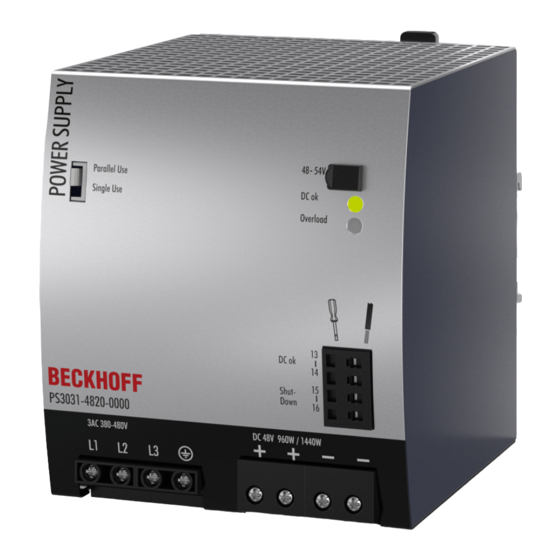
Technical data, mounting, wiring 3.13 Front side and operating elements Fig. 17: PS3031-4820-0000, front Input terminals (screw terminals) Designation (A) Description L1, L2, L3 Mains input L1, L2, L3 PE input (protective conductor) Output terminals (screw terminals, two contact pins per pole) - Page 25 LED displays Overload LED DC-OK LED DC-OK contact Normal mode Closed During extra power Closed Overload (Vout < 90%) Open Short circuit at output Open Temperature switch-off flashes Open Shutdown input active flashes Open No input power Open PS3031-4820-0000 Version: 1.0...
-
Page 26: Emc
Restrictions apply to residential, commercial and light industrial applications as well as to small businesses involving local DC networks according to EN 61000-6-3. No restrictions for all types of industrial applications. Tested with constant current loads, non-pulsating Version: 1.0 PS3031-4820-0000... -
Page 27: Environment
Characteristic curves and figures for operation on two phases of a 3-phase system can be found in chapter Operation on two phases of a 3-phase system [} 36]. Do not energize when condensation is present! Fig. 18: Output current over ambient temperature; output current over installation altitude PS3031-4820-0000 Version: 1.0... -
Page 28: Protective Functions
Typ. 0.45 mA / 0.91 mA At 3x 480 Vac, 60 Hz, TN, TT / IT network Max. 0.45 mA / 0.78 mA At 3x 440 Vac, 50 Hz, TN, TT / IT network Max. 0.60 mA / 1.20 mA At 3x 528 Vac, 60 Hz, TN, TT / IT network Version: 1.0 PS3031-4820-0000... -
Page 29: Dielectric Strength
This helps to avoid situations where a load starts unexpectedly or cannot be disconnected if an unnoticed earth leakage occurs. PS3031-4820-0000 Version: 1.0... -
Page 30: Declaration Of Conformity And Approvals
Technical data, mounting, wiring 3.19 Declaration of conformity and approvals EU declaration of conformity UL Certificate, UL508 Applicable for US and Canada Version: 1.0 PS3031-4820-0000... -
Page 31: Dimensions And Weight
Use 35 mm DIN rails according to EN 60715 or EN 50022 with a height of 7.5 or 15 mm. Housing material Housing: Aluminum alloy Cover: galvanized steel Installation clearances See chapter on Safety instructions and installation requirements [} 8] Fig. 20: Front/side view of PS3031-4820-0000, all specifications in mm PS3031-4820-0000 Version: 1.0... -
Page 32: Application Notes
Fig. 21: Repeated pulse loads, definitions; Max. duty cycle curve Base load (W) Pulse load (over 100%) PEAK Duration between pulses (s) Pulse duration (s) PEAK Calculation: Duty cycle = T / (T PEAK PEAK = (T - (DutyCycle x T )) / DutyCycle PEAK PEAK Version: 1.0 PS3031-4820-0000... - Page 33 )) / DutyCycle = (1 s - (0.37 x 1 s)) / 0.37 = 1.7 s PEAK PEAK Further examples of pulse load tolerance PEAK PEAK 1440 W 960 W 1 s >25 s 1440 W 0 W 1 s >1.3 s 1200 W 480 W 1 s > 0.75 s 1440 W 480 W 0.1 s >0.16 s 1440 W 480 W 1 s >1.6 s 1440 W 480 W 3 s >4.9 s PS3031-4820-0000 Version: 1.0...
-
Page 34: Peak Current Capability
Peak current voltage drops Typically from 48 V to 44 V At 40 A for 50 ms, ohmic load Typically from 48 V to 38 V At 100 A for 2 ms, ohmic load Typically from 48 V to 33 V At 100 A for 5 ms, ohmic load Version: 1.0 PS3031-4820-0000... -
Page 35: External Input Protection
If an external fuse is required or used, minimum requirements must be taken into account to avoid false tripping of the circuit breaker. • A circuit breaker with a minimum value of 6 A with B or C characteristic should be used. PS3031-4820-0000 Version: 1.0... -
Page 36: Operation On Two Phases Of A 3-Phase System
• This kind of operation is not covered by the UL approval. Additional testing may be required if the complete system has to be approved according to UL 508 or UL 60950-1. Fig. 24: When using only two phases: Permissible output current; hold-up time Fig. 25: Efficiency over output current at 48 V; losses over output current at 48 V Version: 1.0 PS3031-4820-0000... -
Page 37: Output Circuit Breakers
12 m 19 m 29 m 42 m B-16A 6 m 8 m 12 m 20 m B-20A 1 m 2 m 4 m 5 m Don't forget to double the distance to the load (or the cable length) when calculating the total cable length (plus and minus cable). PS3031-4820-0000 Version: 1.0... -
Page 38: Charging Batteries
The power supply is not recommended for charging lead-acid batteries or maintenance-free batteries (SLA or VRLA batteries). The PS3031-4820-0000 power supply cannot provide the recommended end-of-charge voltage of 55.0 V (at 20°C) for four 12 V lead-acid batteries in series. Series connection Power supplies of the same type can be connected in series to increase the output voltages. -
Page 39: Parallel Use To Increase Power
The maximum permissible feed-back voltage is 63 Vdc. The absorbing energy can be calculated according to the large built-in output capacitor indicated in the output data, see Output [} 13] chapter. PS3031-4820-0000 Version: 1.0... -
Page 40: Use In A Tightly Sealed Enclosure
The extent of the reduction influences the lifetime expectancy of the power supply. Therefore, two different derating curves for continuous operation are provided below: Curve A1: Recommended output current. Curve A2: Max. permissible output current (results in about half the lifetime expectancy of A1). Fig. 29: Installation position A (standard installation position) Version: 1.0 PS3031-4820-0000... - Page 41 Application notes Fig. 30: Installation position B (upside down) Fig. 31: Installation position C (table mounting) Fig. 32: Installation position D (horizontal clockwise) Fig. 33: Installation position E (horizontal counterclockwise) PS3031-4820-0000 Version: 1.0...
-
Page 42: Appendix
This bracket is used to mount the devices to a wall or panel without using a DIN rail. Fig. 34: ZS5301-0002, isometric view Documentation issue status Version Comment • First release • Corrections • Preliminary documentation for PS3031-4820-0000 Version: 1.0 PS3031-4820-0000... -
Page 43: Support And Service
Please contact your Beckhoff branch office or representative for local support and service on Beckhoff products! The addresses of Beckhoff's branch offices and representatives round the world can be found on her internet pages: https://www.beckhoff.com/english/beckhoff/world.htm You will also find further documentation for Beckhoff components there. - Page 45 More Information: www.beckhoff.com/ps3031-4820-0000 Beckhoff Automation GmbH & Co. KG Hülshorstweg 20 33415 Verl Germany Phone: +49 5246 9630 info@beckhoff.com www.beckhoff.com...
Need help?
Do you have a question about the PS3031-4820-0000 and is the answer not in the manual?
Questions and answers