Advertisement
Quick Links
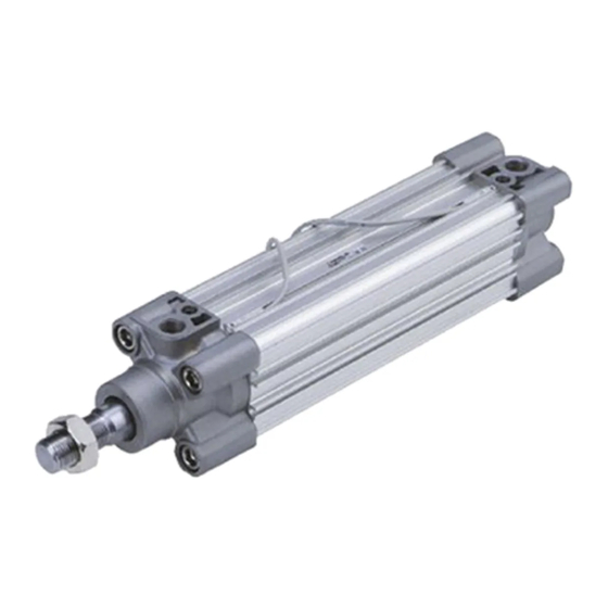
• CNOMO and circular grooves are set on all four sides.
• Switch can slide in.
Profile Design ISO Cylinder
CP96
Series
Variations
Series
Series CP96
Standard
Variations
Series
Series C96
Standard
CP96/C96
Series
ø32, ø40, ø50, ø63, ø80, ø100, ø125
Action
Type
Single
Non-
rod
lube
Double
acting
Double
Non-
rod
lube
Action
Type
Single
Non-
rod
lube
Double
acting
Double
Non-
rod
lube
ISO Cylinders
Standard variations
Basic
Built-in
Stainless
magnet
steel rod
Standard variations
Basic
Built-in
Stainless
magnet
steel rod
C96
Series
Option
Bore (mm)
Heat resistant
32, 40, 50, 63
80, 100, 125
Option
Bore (mm)
Heat resistant
32, 40, 50, 63
80, 100, 125
CAT.ES20-204A
Advertisement

Related Manuals for SMC Networks CP96 Series


Summary of Contents for SMC Networks CP96 Series
- Page 1 ISO Cylinders ø32, ø40, ø50, ø63, ø80, ø100, ø125 • CNOMO and circular grooves are set on all four sides. • Switch can slide in. Profile Design ISO Cylinder CP96 Series Series Variations Standard variations Option Series Action Type Basic Bore (mm) Built-in Stainless...
- Page 3 Profile Design ISO Cylinder CP96 Series ø32, ø40, ø50, ø63, ø80, ø100, ø125 Profile design with enclosed tie-rods Variations Standard variations Option Action Series Type Bore (mm) Basic Built-in Stainless Heat magnet steel rod resistant Standard Non- Single CP96 Series lube Double 32, 40, 50, 63...
- Page 4 Profile Design ISO Cylinder ø32, ø40, ø50, ø63, ø80, ø100, ø125 CP96 Series Improved end of stroke cushion capacity Piston rod lurching has been eliminated at the end of stroke Port aperture positions by means of a floating seal mechanism. Easy end of stroke cushion valve adjustment Since adjustment of the cushion valve is performed...
- Page 5 ∗∗ D-M9BM, M9NM, M9PM type (product of 1 m in length of the lead wire) are applicable from the shipment in May, 2008. Note) D-Y59A, Y69A, Y7P, Y7„W, Z7„, Z80 type cannot be mounted on the CP96 series. Moreover, D-M9„„ and A9„ type cannot be mounted on square groove of the CP96 series.
- Page 6 ISO Cylinder: Standard CP96 Series Double Acting w/ End of Stroke Cushioning Accessories Cylinder Mounting Accessories Female head end clevis Rod/Head end flange Male head end clevis (Corresponds to E accessory) Bore size (mm) Supplied with 4 screws. Supplied with bolt, safety device and 4 screws. Supplied with 4 screws.
- Page 7 CP96 Series Specifications Bore size (mm) Action Double acting Fluid Proof pressure 1.5 MPa Max. operating pressure 1.0 MPa Min. operating pressure 0.05 MPa Ambient and fluid Without auto switch: –20 to 70°C temperature With auto switch: –10 to 60°C Lubrication Not required (Non-lube) 50 to 1000 mm/s...
- Page 8 ISO Cylinder: Standard CP96 Series Double Acting w/ End of Stroke Cushioning Theoretical Output Allowable Kinetic Energy Bore Piston Operating pressure (MPa) Operating 10000 size diameter area direction (mm) (mm) ø125 1257 1006 1131 1257 ø100 1056 1056 ø80 1963 1178 1374 1570...
- Page 9 CP96 Series Construction [First angle projection] ø125 ø80 to ø125 ø80 to ø125 (No flat washer for ø125) Component Parts Replacement Parts: Seal Kit Bore size (mm) Kit no. Contents Description Material Note Rod cover Aluminum die-casted CS95-32 CS95-40 Head cover Aluminum die-casted CS95-50 Cylinder tube...
- Page 10 ISO Cylinder: Standard CP96 Series Double Acting w/ End of Stroke Cushioning Dimensions: Without Mounting Bracket [First angle projection] CP96S(D)B Bore size - Stroke 2 x EE Cushion valve 8 x RT L8 + Stroke ZZ + Stroke CP96S(D)B Bore size - Stroke 2 x EE Cushion valve...
- Page 11 CP96 Series Dimensions: Cylinder Mounting Accessories (L/F/G/C/D) [First angle projection] Mounting (L) XA + Stroke 4 x øAB SA + Stroke Mounting (F/G) Head end mounting (G) 4 x FB ZF + Stroke Rod end mounting (F) Mounting (C) Mounting (D) XD + Stroke Bore size øCD...
- Page 12 ISO Cylinder: Standard CP96 Series Double Acting w/ End of Stroke Cushioning Dimensions: Cylinder Mounting Accessories (C/D/E/CS) [First angle projection] Mounting (C) Mounting (D) Bore size ød øCD MR ød (mm) –0.2 32.5 –0.6 –0.2 –0.6 –0.2 46.5 –0.6 –0.2 56.5 –0.6 –0.2...
- Page 13 CP96 Series Dimensions: Cylinder Mounting Accessories (DS/ES) [First angle projection] Mounting (DS) Bore size ød ød ød øCN (mm) min. max. max. 11.5 32.5 10.5 46.5 56.5 13.5 ∗ Black color Mounting (ES) Bore size ød øCN øS (mm) max. max.
- Page 14 ISO Cylinder: Standard CP96 Series Double Acting w/ End of Stroke Cushioning Dimensions: Piston Rod Mounting Accessories [First angle projection] Floating Joint JA Bore size (mm) Part no. øD Load (kN) Mass (g) Angle M10 x 1.25 JA30-10-125 49.5 19.5 —...
- Page 15 CP96 Series Minimum Stroke for Auto Switch Mounting (mm) Auto switch Number of auto model switch mounted 2 switches (Different side, Same side) D-M9„ 1 switch Other qty. 15+5 (n-2) 10+10 (n-2) 2 switches (Different side, Same side) D-M9„W D-M9„AL 1 switch Other qty.
- Page 16 A torque of 0.05 to 0.15 N ·m should be used for D-M9„, M9„W, M9„AL, and 0.10 to 0.20 N · m for D-A9„. Once the screw starts to feel tight, tighten it further by approximately another 90°. Note) D-M9„„ and A9„ type cannot be mounted on square groove of the CP96 series.
- Page 18 ISO Cylinder Series ø32, ø40, ø50, ø63, ø80, ø100, ø125 Conforming to ISO 15552 Variations Standard variations Option Action Series Type Bore (mm) Basic Built-in Stainless Heat magnet steel rod resistant Standard Non- Single Series lube 32, 40, 50, 63 Double acting 80, 100, 125...
- Page 19 ISO Cylinder: Standard Double Acting, Single/Double Rod Series ø32, ø40, ø50, ø63, ø80, ø100, ø125 How to Order C96S B 32 Without auto switch C96SD B 32 With auto switch M9BW Built-in magnet Number of Mounting auto switches Bore size Basic/Without bracket 2 pcs.
- Page 20 ISO Cylinder: Standard Series Double Acting, Single/Double Rod Accessories Cylinder Mounting Accessories Female head end clevis Rod/Head end flange Male head end clevis (Corresponds to E accessory) Bore size (mm) Supplied with 4 screws. Supplied with bolt, safety device and 4 screws. Supplied with 4 screws.
- Page 21 Series Specifications Bore size (mm) Action Double acting Fluid Proof pressure 1.5 MPa Max. operating pressure 1.0 MPa Min. operating pressure 0.05 MPa Ambient and fluid Without auto switch: –20 to 70°C temperature With auto switch: –10 to 60°C Lubrication Not required (Non-lube) 50 to 1000 mm/s 50 to 700 mm/s...
- Page 22 ISO Cylinder: Standard Series Double Acting, Single/Double Rod Theoretical Output Allowable Kinetic Energy Bore Piston Operating pressure (MPa) Operating 10000 size diameter area direction (mm) (mm) ø125 1257 1006 1131 1257 ø100 1056 1056 ø80 1963 1178 1374 1570 1767 1963 ø63 1649...
- Page 23 Series Construction [First angle projection] ø125 ø80 to ø125 ø80 to ø125 (No flat washer for ø125) Component Parts Replacement Parts: Seal Kit Bore size (mm) Kit no. Contents Description Material Note Rod cover Aluminum die-casted CS95-32 CS95-40 Head cover Aluminum die-casted CS95-50 Cylinder tube...
- Page 24 ISO Cylinder: Standard Series Double Acting, Single/Double Rod Dimensions: Without Mounting Bracket [First angle projection] C96S(D)B Bore size - Stroke 2 x EE Cushion 8 x RT valve L8 + Stroke ZZ + Stroke C96S(D)B Bore size - Stroke 2 x EE Cushion 8 x RT valve...
- Page 25 Series Dimensions: Cylinder Mounting Accessories [First angle projection] Foot (L) XA + Stroke 4 x øAB SA + Stroke Z + 1/2 Stroke Center trunnion (T) XV + 1/2 Stroke Flange (F/G) 4 x FB Head end mounting (G) ZF + Stroke Rod end mounting (F) Head end Head end...
- Page 26 ISO Cylinder: Standard Series Double Acting, Single/Double Rod Dimensions: Cylinder Mounting Accessories (C/D/E/CS) [First angle projection] Mounting (C) Mounting (D) Bore size ød øCD MR ød (mm) –0.2 32.5 –0.6 –0.2 –0.6 –0.2 46.5 –0.6 –0.2 56.5 –0.6 –0.2 –0.6 –0.2 –0.6 Max.
- Page 27 Series Dimensions: Cylinder Mounting Accessories (DS/ES) [First angle projection] Mounting (DS) Bore size ød ød ød øCN (mm) min. max. max. 11.5 32.5 10.5 46.5 56.5 13.5 ∗ Black color Mounting (ES) Bore size ød øCN øS (mm) max. max. max.
- Page 28 ISO Cylinder: Standard Series Double Acting, Single/Double Rod Dimensions: Piston Rod Mounting Accessories [First angle projection] Floating Joint JA Bore size (mm) Part no. øD Load (kN) Mass (g) Angle M10 x 1.25 JA30-10-125 49.5 19.5 — M12 x 1.25 JA40-12-125 —...
- Page 29 Series Minimum Stroke for Auto Switch Mounting (mm) Auto Number of Center trunnion Support bracket other than Center trunnion switch auto switch ø32, ø40, ø32 ø40 ø50 ø63 ø80 ø100 ø125 ø80, ø100 ø125 model mounted ø50, ø63 1 switch, 2 switches (Different side, Same side) D-A9„...
- Page 30 Series Auto Switch Proper Mounting Position (Detection at Stroke End) and Its Mounting Height [First angle projection] Auto switch ≈ Auto Switch Proper Mounting Position (mm) Auto D-Z7„ switch D-Z80 D-M9„ D-F5„W model D-Y59„ D-M9„V D-J59W D-A3„ D-Y69„ D-A9„ D-M9„W D-A5„...
- Page 31 Series Auto Switch Mounting Bracket Part No. Bore size (mm) Auto switch model ø32 ø40 ø50 ø63 ø80 ø100 ø125 D-A9„/A9„V D-M9„/M9„V BMB5-032 BMB5-032 BA7-040 BA7-040 BA7-063 BA7-063 BA7-080 D-M9„W/M9„WV D-M9„AL/M9„AVL D-A3„/A44 BMB2-032 BMB2-040 BMB1-050 BMB1-063 BMB1-080 BMB1-100 BS1-125 D-G39/K39 D-A5„/A6„...
- Page 32 Series Besides the models listed “How to Order,” the following auto switches are applicable. For detailed auto switch specifications, refer to SMC “Best Pneumatics 2004” catalogs. Type Auto switch model Electrical entry Features ∗∗ D-M9NV, M9PV, M9BV — D-Y69A, Y69B, Y7PV D-M9NWV, M9PWV, M9BWV Grommet (Perpendicular) Diagnosis indication (2-color)
- Page 33 Series How to Mount and Move the Auto Switch Mounting Bracket Tie-rod Mounting <Applicable Auto Switch> <Applicable Auto Switch> Solid state switch ··· D-G39, D-K39 Solid state switch · ·· D-M9N(V), D-M9P(V), D-M9B(V) Reed switch ··· ·· ·· ·· · D-A33, D-A34, D-A44 D-M9NW(V), D-M9PW(V), D-M9BW(V) D-M9NA(V), D-M9PA(V), D-M9BA(V) Reed switch ···...
- Page 34 How to Mount and Move the Auto Switch <Applicable Auto Switch> <Applicable Auto Switch> Solid state switch ··· D-Y59 , Y69 , D-Y7P(V) Solid state switch · ·· D-P4DWL D-Y7NW(V), Y7PW(V), Y7BW(V) D-Y7BAL Reed switch ··· ·· ·· ·· · D-Z73, Z76, Z80 How to Mount and Move the Auto Switch How to Mount and Move the Auto Switch Watchmaker’s (precision) screwdriver...
- Page 35 How to Mount and Move the Auto Switch Mounting Bracket Tie-rod Mounting <Applicable Auto Switch> Solid state switch ··· D-F59, D-F5P Auto switch mounting screw (M4) D-J59, D-J51, D-F5BAL D-F59W, D-F5PW, D-J59W D-F59F, D-F5NTL Reed switch ··· ·· ·· ·· · D-A53, D-A54, D-A56, D-A64, D-A67 Auto switch D-A59W Auto switch mounting bracket...
- Page 36 Safety Instructions These safety instructions are intended to prevent hazardous situations and/or equipment damage. These instructions indicate the level of potential hazard with the labels of “Caution,” “Warning” or “Danger.” They are all important notes for safety and must be followed in addition to International ∗1) ∗2) Standards (ISO/IEC), Japan Industrial Standards (JIS)
- Page 37 Safety Instructions Caution The product is provided for use in manufacturing industries. The product herein described is basically provided for peaceful use in manufacturing industries. If considering using the product in other industries, consult SMC beforehand and exchange specifications or a contract if necessary.
- Page 38 Actuators Precautions 1 Be sure to read this before handling. Design and Selection Warning 9. Consider the action when operation is restarted after an emergency stop or abnormal stop. 1. There is a danger of sudden action by air cylinders if Design the machinery so that human injury or equipment dam- sliding parts of machinery are twisted, etc., and age will not occur upon restart of operation.
- Page 39 Actuators Precautions 2 Be sure to read this before handling. Mounting Cushion Caution Caution 1. Be certain to align the rod axis with the load and di- 1. Readjust using the cushion needle. rection of movement when connecting. Cushion is adjusted at the factory, however, the cushion needle on the cover should be readjusted when the product is put into When not properly aligned, the rod and tube may be twisted, service, based upon factors such as the size of the load and the...
- Page 40 CP96/C96 Series Auto Switches Precautions 1 Be sure to read this before handling. Design and Selection Warning Caution 1. Confirm the specifications. 2. Keep wiring as short as possible. Read the specifications carefully and use this product appro- <Reed switches> priately.
- Page 41 D-Y59A, Y69A, Y7P, Y7„W, Z7„, Z80 type cannot be moun- the load. ted on the CP96 series. Moreover, D-M9„„ and A9„ type Supply Internal voltage Minimum operating cannot be mounted on square groove of the CP96 series.
- Page 42 CP96/C96 Series Auto Switches Precautions 3 Be sure to read this before handling. Wiring Caution Caution 1. Confirm proper insulation of wiring. 6. Avoid incorrect wiring. Be certain that there is no faulty wiring insulation (contact with <Reed switches> other circuits, ground fault, improper insulation between termi- A 24 VDC auto switch with indicator light has polarity.
- Page 43 CP96/C96 Series Auto Switches Precautions 4 Be sure to read this before handling. Operating Environment Warning Caution 1. Never use in an atmosphere of explosive gases. 7. Avoid accumulation of iron waste or close contact with magnetic substances. The structure of auto switches is not intended to prevent explo- sion.
- Page 47 SMC'S GLOBAL MANUFACTURING, DISTRIBUTION AND SERVICE NETWORK EUROPE NETHERLANDS SINGAPORE SMC Pneumatics B.V. SMC Pneumatics (S.E.A.) Pte. Ltd. AUSTRIA NORWAY SMC Pneumatik GmbH (Austria) SOUTH KOREA SMC Pneumatics Norway AS SMC Pneumatics Korea Co., Ltd. BELGIUM POLAND SMC Pneumatics N.V./S.A. TAIWAN SMC Industrial Automation Polska Sp.z.o.o.
Need help?
Do you have a question about the CP96 Series and is the answer not in the manual?
Questions and answers