SMC Networks C96 Series Instructions Manual
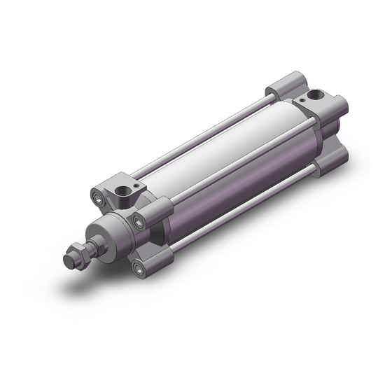
Iso cylinder
Hide thumbs
Also See for C96 Series:
- Manual (47 pages) ,
- Manual (27 pages) ,
- Instruction manual (108 pages)
Advertisement
Quick Links
ISO Cylinder
ø32, ø40, ø50, ø63, ø80, ø100
Lightweight
* Compared with the existing C96 series (ø40, 100 stroke)
By adopting a new cushion method
Cycle time shortened
Air cushion
Existing
Air cushion
New
New
Bumper cushion
Bumper cushion reduces the metal noise that occurs when piston stops
C96
Series
17
% Weight reduced
Up
to
Cushion stroke time
Air cushion
+
ISO Standard (15552)
(Air cushion
Air cushion
Bumper cushion
+
Bumper
cushion),
Shortened
CAT.ES20-242A
Advertisement

Related Manuals for SMC Networks C96 Series


Summary of Contents for SMC Networks C96 Series
- Page 1 ISO Cylinder ISO Standard (15552) ø32, ø40, ø50, ø63, ø80, ø100 % Weight reduced Lightweight * Compared with the existing C96 series (ø40, 100 stroke) By adopting a new cushion method (Air cushion Bumper cushion), Cycle time shortened Cushion stroke time...
- Page 2 Bumper cushion Air cushion 0.96 1.57 1.94 3.12 4.03 * Compared with the existing C96 series (ø40, 100 stroke) Rod end nut can be screwed up to TRP. Small sized auto switch can be attached. Solid state: D-M9l Reed: D-A9l...
- Page 3 ISO Cylinder Various mounting bracket options Mounting brackets can be combined according to the operating conditions. Piston rod ball joint (KJ) Rod clevis (GKM) Floating joint (JA) Double clevis (D) Series Single clevis (C) Clevis pivot Rod flange (F) bracket (E) Double clevis pivot bracket (DS) Single clevis (C)
- Page 4 ISO Standard (15552) Air Cylinder: Standard Type Double Acting, Single Rod Series ø32, ø40, ø50, ø63, ø80, ø100 How to Order C96S B 32 100 C96SD B 32 100 M9BW With auto switch With auto switch Number of auto switches (Built-in magnet) 2 pcs.
- Page 5 Air Cylinder: Standard Type ISO Standard (15552) Series Double Acting, Single Rod Specifications Bore size (mm) Action Double acting Fluid Proof pressure 1.5 MPa Max. operating pressure 1.0 MPa Min. operating pressure 0.05 MPa Without auto switch : –20 to 70°C (No freezing) Ambient and fluid temperature With auto switch...
- Page 6 Series Theoretical Output Allowable Kinetic Energy Bore Piston Operating pressure (MPa) Rod size Operating size area 1000 (mm) direction ø (mm) ø ø 1257 880 1006 1131 1257 ø 1056 950 1056 ø 1963 982 1178 1374 1570 1767 1963 ø...
- Page 7 Air Cylinder: Standard Type ISO Standard (15552) Series Double Acting, Single Rod Construction [First angle projection] !3 @1 !9 !4 !8 @2 !7 @0 ø ø ø ø Component Parts Replacement Parts/Seal Kit (Single rod) Description Material Note Bore size (mm) Kit no.
- Page 8 Series Dimensions [First angle projection] C96S (D) B Basic: Bore size Stroke ø ø x EE ø ø x EE port Width across flats Cushion valve x RT + Stroke + Stroke ø ø x RT (mm) Bore Stroke ø BG øD E SL SW VA VD WA WB WH ZZ size...
- Page 9 Air Cylinder: Standard Type ISO Standard (15552) Series Double Acting, Single Rod Dimensions [First angle projection] Axial foot ( (mm) + Stroke Bore TR AH AO AT AB SA XA size (mm) 48 32 32 10 4.5 7 142 144 55 36 36 11 4.5 10 161 163 68 45 45 12 5.5 10 170 175 øAB...
- Page 10 Series Accessories Dimensions: Mounting Brackets [First angle projection] Axial foot ( (mm) Bore TR AO AU AH AT size Part no. Screw size ±0.2 (mm) L5032 32.5 32 4.5 15 M6 x 16L L5040 36 4.5 17.5 M6 x 16L L5050 46.5 45 5.5 20...
- Page 11 Series Accessories Dimensions: Mounting Brackets, Pivot Brackets for Cylinder Mounting [First angle projection] Double clevis ( (mm) Bore CD MR UB CB size Part no. ø ø ø (mm) D5032 32.5 22 5.5 30 9.5 6.6 6.5 48 45 26 D5040 5.5 35 12 12...
- Page 12 Series Dimensions: Pivot Brackets for Cylinder Mounting [First angle projection] Double clevis pivot bracket ( )/for ES accessory +0.3 (mm) Bore size Part no. ø ø ø ø (Max.) (Max.) (Min.) (mm) DS5032 11.5 32.5 10.5 DS5040 DS5050 46.5 DS5063 56.5 DS5080 DS5100...
- Page 13 Series Accessories Dimensions: Piston Rod Accessories [First angle projection] Floating joint: (mm) Bore size (mm) Part no. Load (kN) Weight (g) Angle ø JA30-10-125 M10 x 1.25 49.5 19.5 — JA40-12-125 M12 x 1.25 — 0.75 ±0.5° 50, 63 JA50-16-150 M16 x 1.5 71.5 —...
- Page 14 Series Auto Switch Mounting Minimum Stroke for Auto Switch Mounting (mm) Support bracket other than center trunnion Auto switch Number of auto switches model ø32 ø40 ø50 ø63 ø80, ø100 With 1 pc. With 2 pcs. D-M9l (Different surfaces, Same surface) D-M9lW 10 + 40 (n –...
- Page 15 Series Auto Switch Mounting (mm) Center trunnion Auto switch Number of auto switches model ø32 ø40 ø50 ø63 ø80 ø100 With 1 pc. With 2 pcs. D–M9l (Different surfaces, Same surface) D–M9lW 75 + 40 (n – 4) /2 85 + 40 (n – 4) /2 90 + 40 (n –...
- Page 16 Series Auto Switch Proper Mounting Position (Detection at stroke end) and Its Mounting Height ≈ Auto switch Auto Switch Proper Mounting Position (mm) D-Y59 Auto switch D-G39 D-Y69 model D-K39 D-Y7P D-M9l D-F5l D-A9l D-Y7H D-A3l D-M9lV D-P4DW D-J5l D-J51 D-A59W D-F5NT D-A9lV...
- Page 17 Series Auto Switch Mounting Auto Switch Mounting Brackets/Part No. Bore size (mm) Auto switch model ø32 ø40 ø50 ø63 ø80 ø100 D-M9l/M9lV D-M9lW/M9lWV BMB5-032 BMB5-032 BA7-040 BA7-040 BA7-063 BA7-063 D-M9lA/M9lAV D-A9l/A9lV D-G39/K39 BMB2-032 BMB2-040 BMB1-050 BMB1-063 BMB1-080 BMB1-100 D-A3l/A44 D-F5l/J5l D-F5lW/J59W D-F59F D-F5BA...
- Page 18 Series Other than the applicable auto switches listed in “How to Order”, the following auto switches are mountable. Refer to the WEB catalog or the Best Pneumatics No. 2 for the detailed specifications. Type Part no. Electrical entry Features D-M9NV, M9PV, M9BV —...
- Page 19 Series How to Mount and Move the Auto Switch Mounting Bracket Tie-rod Mounting Type <Applicable Auto Switch> <Applicable Auto Switch> Solid state switch ··· D-G39, D-K39 Solid state switch ·· · D-M9N(V), D-M9P(V), D-M9B(V) Reed switch ·········· D-A33, D-A34, D-A44 D-M9NW(V), D-M9PW(V), D-M9BW(V) D-M9NA(V), D-M9PA(V), D-M9BA(V) Reed switch ···...
- Page 20 Series Mounting Bracket Tie-rod Mounting Type <Applicable Auto Switch> <Applicable Auto Switch> Solid state switch · ·· D-Y59 , Y69 , D-Y7P(V) Solid state switch ·· · D-P4DW D-Y7NW(V), Y7PW(V), Y7BW(V) D-Y7BA Reed switch · ··· ··· ··· D-Z73, Z76, Z80 How to Mount and Move the Auto Switch How to Mount and Move the Auto Switch Hexagon socket...
- Page 21 Series How to Mount and Move the Auto Switch Mounting Bracket Tie-rod Mounting Type <Applicable Auto Switch> Solid state switch ··· D-F59, D-F5P Auto switch mounting screw (M4) D-J59, D-J51, D-F5BA D-F59W, D-F5PW, D-J59W D-F59F, D-F5NT Reed switch · ·· ··· ··· · D-A53, D-A54, D-A56, D-A64, D-A67 Auto switch D-A59W Auto switch mounting bracket...
- Page 22 Prior to Use Auto Switch Connection and Example Sink Input Specifications Source Input Specifications 3-wire, NPN 3-wire, PNP Brown Input Brown Input Black Black Auto switch Auto switch Blue Blue (PLC internal circuit) (PLC internal circuit) 2-wire 2-wire Brown Input Brown Auto switch Auto switch...
- Page 23 Series Specific Product Precautions Be sure to read this before handling. Refer to the back cover for Safety Instructions. For Actuator and Auto Switch Precautions, refer to “Handling Precautions for SMC Products” and the Operation Manual on SMC website, http://www.smcworld.com Adjustment Warning 1.
- Page 24 These safety instructions are intended to prevent hazardous situations and/or Safety Instructions equipment damage. These instructions indicate the level of potential hazard with the labels of “Caution,” “Warning” or “Danger.” They are all important notes for ∗1) safety and must be followed in addition to International Standards (ISO/IEC) and other safety regulations.
Need help?
Do you have a question about the C96 Series and is the answer not in the manual?
Questions and answers