
Related Manuals for SMC Networks VM1000 Series


Summary of Contents for SMC Networks VM1000 Series
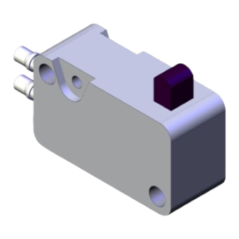
- Page 1 Document No.DOC1021327-2 Pr oduct Name Micro Mechanical Valve Model/ Series VM1000 Series...
-
Page 2: Table Of Contents
Contents 1. Safety Instructions 2. Application 3. Specifications 4. How to order 5. Strokes 6. Installation and Mounting Orientation 7. Operating Force 8. Mechanical Operating Conditions 9.Replacement Parts... -
Page 3: Safety Instructions
Safety Instructions These safety instructions are intended to prevent hazardous situations and/or equipment damage. These instructions indicate the level of potential hazard with the labels of “Caution,” “Warning” or “Danger.” They are all important notes for safety and must be followed in addition to International Standards (ISO/IEC) , and other safety regulations. - Page 4 Safety Instructions Caution We develop, design, and manufacture our products to be used for automatic control equipment, and provide them for peaceful use in manufacturing business. Use in non-manufacturing business is not covered. Products we manufacture and sell cannot be used for the purpose of transactions or certification specified in the Measurement Act.
- Page 5 Design precautions Warning ! 1. Actuator drive When an actuator, such as a cylinder, is to be driven take appropriate measures to prevent potential danger caused by actuator operation. 2. Maintenance space When installing the products, allow access for maintenance. 3.
- Page 6 3. Do not wipe the product using chemicals. Piping Caution ! 1. Before piping Before piping, perform air blow (flushing) or cleaning to remove any cutting chips, cutting oil, dust, etc. from the piping. 2. Piping to product When piping to the product, refer to the symbols and labels on the product to avoid mistakes in the position of the supply port, etc.
- Page 7 3. If excessive carbon powder is seen, install a mist separator on the upstream side of the valve. If excessive carbon powder is generated by the compressor, it may adhere to the inside of the valves and cause malfunction. 4. Grease is applied to the inner parts of the valve. Grease may enter on the downstream side of the valve.
- Page 8 Specific Product Precautions for Mechanical Valve Design precautions Warning ! 1. Cannot be used for sealing pressure. Since VM1000 is a poppet type valve, fluid flows backwards when the pressure on port 2 rises. Since the valve is subject to a little amount of air leakage, it cannot be used for applications such as holding pressure (including vacuum).
- Page 9 This could damage the mechanical valve itself and lead to equipment malfunction. Refer to Chapter 8, "Mechanical Operating Conditions" in this Operation Manual for the main precautions. Caution ! 1. After operating for a long time, it will take some time for the valve to restart as the resistance between the seal and the parts increases.
-
Page 10: Application
2. Application VM1000 mechanical valve is applied to a pneumatics air pressure control circuit in a machine tool, a small-size industrial machine, and others as a signal valve. For actuator types, a roller lever for mechanical operation, and push button and flip toggle for manual operation are available. -
Page 11: Strokes
5.Strokes 5-1. Definition of Symbol F.O.F. F.O.F. F.O.F. <Full Operating Force> --- Required force to total travel position, from free position of the actuator to total travel position. P.T. <Pre-travel> --- From free position to initial valve operating position. O.T. <Over Travel> --- From initial valve operating position to total travel position. T.T. -
Page 12: Installation And Mounting Orientation
6.Installation and Mounting Orientation 6-1. Model Type Mounting dimensions 2 port 3 port Mounting plate VM1100-4N-01 VM1000-4N-01 VM1110-4N-01 VM1010-4N-01 Roller lever M3 screws VM1100-4NU-01 VM1000-4NU-01 VM1110-4NU-01 VM1010-4NU-01 VM1100-4N-02 VM1000-4N-02 One way roller VM1110-4N-02 VM1010-4N-02 lever VM1100-4NU-02 VM1000-4NU-02 VM1110-4NU-02 VM1010-4NU-02 Fix at two points using M3 screws. Panel mounting hole M12 Round lock nut Mounting plate... -
Page 13: Operating Force
7.Operating Force The force required for operating the whole actuator varies depending on the supply pressure. A rough guide for the force required for operating the whole actuator at a given pressure can be calculated by the following formula: F ≒ ×... -
Page 14: Mechanical Operating Conditions
8. Mechanical Operating Conditions 8-1. Stroke range Use a mechanical operating product within the stroke range calculated by the formula below. Stroke range = (P.T. + 0.5 x O.T.) to (P.T. + O.T. -0.1) Actuator Stroke range (mm) 3.7 ~ 4.7 T.T.=4.8mm Basic (2.2~2.4) - Page 15 8-4. Operation mechanism and configuration 1. Avoid acute angles on limit switch actuator. [Not acceptable] [Acceptable] Section 8-2 Section 8-2 Wider than the maximum Not larger than the maximum angle angle Abrupt angle 2. Do not allow stroke beyond the maximum travel position. [Not acceptable] [Acceptable] [Acceptable]...
-
Page 16: Replacement Parts
9. Replacement Parts [Button number] Cover for push Color Push button button 3410701-R 34107031A Black 3410701-B (White only) Green 3410701-G Install the push button and the push button cover by screwing them into the bracket. When installing a panel mount or replacing a push button, perform installation by means of hand tightening. - Page 17 Revision history 0. A complete revision 1. Changed the part number of Cover for push button.2023.4 Safety Instructions changed. 2023.12 4-14-1, Sotokanda, Chiyoda-ku, Tokyo 101-0021 JAPAN Tel: + 81 3 5207 8249 Fax: +81 3 5298 5362 URL https://www.smcworld.com Note: Specifications are subject to change without prior notice and any obligation on the part of the manufacturer.
Need help?
Do you have a question about the VM1000 Series and is the answer not in the manual?
Questions and answers