
Subscribe to Our Youtube Channel
Related Manuals for Abov 8-bit MCU


Summary of Contents for Abov 8-bit MCU
- Page 1 8-bit Microcontrollers Starter Kit Starter Kit Quick Guide Version 1.12 Global Top Smart MCU Innovator, ABOV Semiconductor www.abovsemi.com...
-
Page 2: Table Of Contents
Contents 8-bit MCU starter kit guide Contents Introduction ............................ 4 User requirements .......................... 5 Hardware ..........................5 Software ..........................6 Reference documents ......................6 System requirements ......................7 ABOV website ........................7 OCD debugger (96 series) ......................8 Building and running LED_Blinky project (example A96G140) ..........8 Prepare the Starter Kit board .................... - Page 3 Figure 3. Compiler (Software) ......................... 6 Figure 4. Reference Documents ......................6 Figure 5. Window PC & Micro-B cable ....................7 Figure 6. ABOV Semiconductor Website ....................7 Figure 7. Starter Kit B/D .......................... 9 Figure 8. Starter Kit Jumper & Switch ....................10 Figure 9.
-
Page 4: Introduction
Starter Kit. It offers an easy way to develop an ABOV 8-bit MCU. The 8-bit MCU Starter Kit includes M8051 debugger which is called OCD (for 96 series) or 8- bit Writer (for 94/97 series). Therefore, no additional device is required for debugging. -
Page 5: User Requirements
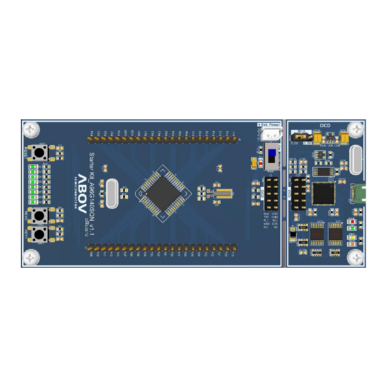
This Starter Kit is available for the devices including 94/ 96/ 97 core series. A96G140, A96G166, A96G174, A94B114, A96L322, A96L523, and etc. This Starter Kit supports additional 8-bit MCU. Figure 1. Starter Kit Board (Hardware) / 96 Series (OCD) Figure 2. Starter Kit Board (Hardware) / 94, 97 Series (8-bit Writer) -
Page 6: Software
2. User requirements 8-bit MCU starter kit guide Software Keil complier (uVision5) EVK software (Including Led_Blinky sample code) Figure 3. Compiler (Software) Reference documents Starter Kit Quick Guide Starter Kit HW Manual Starter Kit Schematic Product User’s Manual Example Code... -
Page 7: System Requirements
8-bit MCU starter kit guide 2. User requirements System requirements Windows PC (7, 8, 10) USB micro-B type cable Figure 5. Window PC & Micro-B cable ABOV website For detailed information about corresponding software and documents, you can visit our website at https://www.abovsemi.com. -
Page 8: Ocd Debugger (96 Series)
3. OCD debugger (96 series) 8-bit MCU starter kit guide OCD debugger (96 series) Building and running LED_Blinky project (example A96G140) Running application code (LED_Blinky) makes it easier to start the Starter Kit. When following the steps below, LEDs on the board turn on and off: Step 1. -
Page 9: Prepare The Starter Kit Board
Pin Headers connected to MCU C. LED, switch and jumper to check input/output, reset, and debugger pins OCD board (debugger) configuration Programmable and debuggable OCD (USB connection to PC) on ABOV 8-bit MCU Device B/D OCD B/D Figure 7. Starter Kit B/D... -
Page 10: Set Up The Starter Kit Board
3. OCD debugger (96 series) 8-bit MCU starter kit guide Set up the Starter Kit Board Set jumpers to control the Starter Kit The Starter Kit uses USB power-① Choose 3.3V and 5.0V (check the maximum operation voltage by referring to the specification sheet). -
Page 11: Connect The Starter Kit To Your Pc
The OCD board (debugger) uses a USB interface. USB driver installation is required. Download the USB driver installation from ABOV website (https://www.abovsemi.com) Once the OCD board (debugger) is connected, it will be shown as “ABOV OCD”. Figure 10. OCD (Debugger) at Device Manager... -
Page 12: Run The Led_Blinky Project
Before downloading the LED blinky example, Keil uVision5 for 8051 and OCD debugger S/W must be installed on your PC. Execute “Keil uVision5”. Execute OCD debugger tool. The debugger software supports the 96 series developed by ABOV 8-bit MCU. Figure 11. Execute Keil uVision5 & OCD Debugger Tool... -
Page 13: Figure 12. Download Evaluation Kit (Example Source)
8-bit MCU starter kit guide 3. OCD debugger (96 series) Download the Evaluation Kit (example source) from ABOV official website. Decompress the file, and select “LED Blinky” in the example sources. Execute “LED Blinky” example project. Figure 12. Download Evaluation Kit (Example Source) -
Page 14: Compiling Led_Blinky
3. OCD debugger (96 series) 8-bit MCU starter kit guide The example source is opened in the location of the configured folder, and uVision5 will be running as shown below. The folder contains the Keil Project and the sample file of the selected example. -
Page 15: Download Led_Blinky
8-bit MCU starter kit guide 3. OCD debugger (96 series) Download Led_Blinky 3.7.1 If the compilation finishes without error, it is possible to download it with OCD debugger software (available only for 96 series). The OCD debugger (via USB) and the Starter Kit are connected and can be downloaded. -
Page 16: Debugging Led_Blinky
3. OCD debugger (96 series) 8-bit MCU starter kit guide Debugging Led_Blinky Debugging in OCD debugger software Enter into debugger mode by executing “Run/Step/Stop Debugger Session”. It must be connected to the Stater Kit for real time debugging. In OCD debugger mode, the program can be executed per Run/Step/Stop Debugger Session. -
Page 17: Check The Led_Blinky Operation
8-bit MCU starter kit guide 3. OCD debugger (96 series) Check the Led_Blinky operation How to check the LED operation After normal download of the Led Blinky program, re-apply the power (removing the USB cable) to check whether the LED is on or off. -
Page 18: 8-Bit Writer (94, 97 Series)
4. 8-bit Writer (94, 97 Series) 8-bit MCU starter kit guide 8-bit Writer (94, 97 Series) Building and running LED_Blinky project (example A94B114) Running application code (LED_Blinky) makes it easier to start the Starter Kit. When following the steps below, LEDs on the board turn on and off: Step 1. -
Page 19: Prepare The Starter Kit Board
Pin headers connected to MCU C. LED, switch and jumper to check input/output, reset, and debugger pin. 8-bit Writer board configuration Only programmable 8-bit Writer (USB connection to PC) on ABOV 8-bit MCU Device B/D 8-bit Writer B/D Figure 18. Starter Kit B/D... -
Page 20: Set Up The Starter Kit Board
4. 8-bit Writer (94, 97 Series) 8-bit MCU starter kit guide Set up the Starter Kit board Set jumpers to control the Starter Kit The Starter Kit uses USB power-① Choose 3.3V and 5.0V (check the maximum operation voltage by referring to the specification sheet). -
Page 21: Connect The Starter Kit To Your Pc
8-bit MCU starter kit guide 4. 8-bit Writer (94, 97 Series) Connect the Starter Kit to your PC PC connection via USB on the Starter Kit Connect the USB (micro-B type) cable to the Starter Kit as shown in Figure 20. -
Page 22: Figure 21. 8-Bit Writer On Device Manager
4. 8-bit Writer (94, 97 Series) 8-bit MCU starter kit guide Recognition of the hardware (device drivers) on your PC 8-bit Writer uses a USB interface. For 8-bit Writer, USB driver installation is not required (USB HID class). Connected 8-bit Writer Disconnected 8-bit Writer Figure 21. -
Page 23: Run The Led_Blinky Project
Before downloading the LED blinky example, Keil uVision5 for 8051 and OCD debugger S/W must be installed on your PC. Execute “Keil uVision5”. Execute 8-bit Writer. The debugger software supports the 94 and 97 series developed by ABOV 8-bit MCU. Figure 22. Execute Keil uVision5 & 8-bit Writer... -
Page 24: Figure 23. Download Evaluation Kit (Example Source)
4. 8-bit Writer (94, 97 Series) 8-bit MCU starter kit guide Download the Evaluation Kit(Example source) from ABOV official website Decompress the file, select “LED Blinky” in the example sources. Execute “LED Blinky” example project. Figure 23. Download Evaluation Kit (Example source) -
Page 25: Compiling Led_Blinky
8-bit MCU starter kit guide 4. 8-bit Writer (94, 97 Series) The example will open in the location of the configured folder and run uVision5 as below The folder contains the Keil Project and the sample file of the selected example Figure 24. -
Page 26: Download Led_Blinky
4. 8-bit Writer (94, 97 Series) 8-bit MCU starter kit guide Download Led_Blinky 4.7.1 8-bit Writer If the compilation finishes without error, it is possible to download it with 8-bit Writer software (called OCD 2 lite tool, available for 94/ 97 series) The 8-bit Writer software (via USB) and the Starter Kit are connected and can be downloaded. -
Page 27: Check The Led_Blinky Operation
8-bit MCU starter kit guide 4. 8-bit Writer (94, 97 Series) Check the Led_Blinky operation How to check the LED operation After normal download of the Led Blinky program, re-apply the power (removing the USB cable) to check whether the LED is on or off. -
Page 28: Revision History
Revision history 8-bit MCU starter kit guide Revision history Date Revision Description 19.11.15 1.00 Document created 20.01.31 1.10 Add ABOV disclaimer 20.02.04 1.11 Changed ABOV website: www.abov.co.kr www.abovsemi.com 20.02.14 1.12 Separated OCD (96 Series) & 8-bit Writer (94, 97 Series) - Page 29 ABOV Semiconductor ("ABOV") reserves the right to make changes, corrections, enhancements, modifications, and improvements to ABOV products and/or to this document at any time without notice. ABOV does not give warranties as to the accuracy or completeness of the information included herein. Purchasers should obtain the latest relevant information of ABOV products before placing orders.
Need help?
Do you have a question about the 8-bit MCU and is the answer not in the manual?
Questions and answers