
Related Manuals for Abov A31T216RLN


Summary of Contents for Abov A31T216RLN
- Page 1 A31T216RLN Shield Board Shield Board Quick Guide Version 1.00 Global Top Smart MCU Innovator, ABOV Semiconductor www.abovsemi.com...
-
Page 2: Table Of Contents
Contents A31T216RLN Shield Board Quick Guide Contents Introduction ............................ 4 User Requirements ........................5 Hardware ..........................5 Software ..........................6 Reference Documents ......................7 System Requirements ......................8 ABOV Website ........................9 Build and Run Project (Shield Board) ..................10 Prepare Starter Kit and Shield Board ................ - Page 3 Figure 4. Reference Document on the ABOV Website ................7 Figure 5. Window PC and Mini-B Cable ....................8 Figure 6. Software and Documents at ABOV Semiconductor Website ..........9 Figure 7. Starter Kit Board ........................11 Figure 8. Components of A31T216RLN Shield Board ................12 Figure 9.
-
Page 4: Introduction
By following the steps guided in this document, users can build a project and download firmware using the Keil uVision 5, and learn how to debug the Starter Kit with the A-Link debugger. In addition, we discuss how to operate the A31T216RLN Shield Board with examples, step by step. -
Page 5: User Requirements
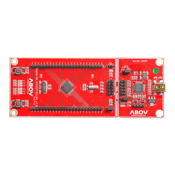
A31T216RLN Shield Board Quick Guide 2. User Requirements User Requirements Hardware Users must prepare the A31T216RLN Starter Kit Board and A31T216RLN Shield Board shown in Figure 1 and Figure 2. Figure 1. A31T216RLN Starter Kit Board (Hardware) Figure 2. A31T216RLN Shield Board (Hardware) -
Page 6: Software
2. User Requirements A31T216RLN Shield Board Quick Guide Software The software users must prepare is as follows: Keil complier (uVision 5) Example Code & Touch Library Figure 3 shows the uVision Editor that includes all standard features of a modern source code editor and is available during debugging. -
Page 7: Reference Documents
A31T216RLN Shield Board Quick Guide 2. User Requirements Reference Documents From the ABOV website, users can find more information about the A31T216RLN Starter Kit and Shield Board as follows: A31T216 Starter Kit Quick Guide A31T216 Starter Kit HW Manual ... -
Page 8: System Requirements
2. User Requirements A31T216RLN Shield Board Quick Guide System Requirements Windows PC (7, 8, and 10) Micro-B 5-pin USB Cable (for Starter Kit) Figure 5. Window PC and Mini-B Cable... -
Page 9: Abov Website
A31T216RLN Shield Board Quick Guide 2. User Requirements ABOV Website Users can find more software and documents at the ABOV website, www.abovsemi.com. Figure 6. Software and Documents at ABOV Semiconductor Website... -
Page 10: Build And Run Project (Shield Board)
3. Build and Run Project (Shield Board) A31T216RLN Shield Board Quick Guide Build and Run Project (Shield Board) Running application code makes it easier to start the Shield Board. Following the steps below: Step 1. Prepare Starter Kit and Shield Board. -
Page 11: Prepare Starter Kit And Shield Board
A31T216RLN Shield Board Quick Guide 3. Build and Run Project (Shield Board) Prepare Starter Kit and Shield Board 3.1.1 Hardware Components of Starter Kit The Starter Kit consists of a device board and an A-Link (CMSIS-DAP) debugger board as shown in Figure 7. It can be used separately as needed. -
Page 12: Hardware Components Of Shield Board
Touch Not Available LED T-Type Matrix 8 x 7 LEDs ISEG0_ICOM0 to ISEG5_ICOM5, ISEG7_ICOM7 to ISEG8_ICOM8 LED M-Type Matrix 8 x 8 LEDs SEG: ISEG6, ISEG9 to ISEG15 COM: ICOM0 to ICOM5, ICOM7 to ICOM8 Figure 8. Components of A31T216RLN Shield Board... -
Page 13: Starter Kit And Shield Board Settings
A31T216RLN Shield Board Quick Guide 3. Build and Run Project (Shield Board) Starter Kit and Shield Board Settings 3.2.1 Jumper Settings for Starter Kit Control The circle numbers in Figure 9 represent the order in which the jumpers are set to control the Starter Kit: The Starter Kit uses the USB power. -
Page 14: Starter Kit Connection For Shield Board Use
3. Build and Run Project (Shield Board) A31T216RLN Shield Board Quick Guide 3.2.2 Starter Kit Connection for Shield Board Use Connect the header sockets on the Shield board and the header pin on the Starter Kit Board, as shown in Figure 10. -
Page 15: Starter Kit Connection To Pc
A31T216RLN Shield Board Quick Guide 3. Build and Run Project (Shield Board) Starter Kit Connection to PC 3.3.1 USB Connection with USB 2.0 Cable Connect a USB 2.0 (Micro-B type) cable to the Starter Kit as shown in Figure 11. When the PC is connected correctly to the other end of the USB 2.0 cable, the following actions are performed:... -
Page 16: Hardware Recognition On Pc (Device Drivers)
3. Build and Run Project (Shield Board) A31T216RLN Shield Board Quick Guide 3.3.2 Hardware Recognition on PC (Device Drivers) The A-Link board (debugger) uses a USB interface. When the A-Link board (debugger) is connected to a PC, it is displayed as ‘USB Composite Device’ in the Serial Bus Controller List, as shown in Figure 12. -
Page 17: Run Starter Kit Shield Board
A31T216RLN Shield Board Quick Guide 3. Build and Run Project (Shield Board) Run Starter Kit Shield Board 3.4.1 Compilation with Keil uVision 5 Using Keil uVision 5, users can compile the provided project files and run the Starter Kit Shield Board. -
Page 18: Figure 14. Project Build In Keil Uvision 5
3. Build and Run Project (Shield Board) A31T216RLN Shield Board Quick Guide Build the project as shown in Figure 14. Figure 14. Project Build in Keil uVision 5... -
Page 19: A-Link Debugger Configuration And Download
A31T216RLN Shield Board Quick Guide 3. Build and Run Project (Shield Board) 3.4.2 A-Link Debugger Configuration and Download When the compilation is completed without errors, users can begin programming the Starter Kit. Downloading is enabled since the Starter Kit is connected to the USB port on the PC. -
Page 20: Figure 16. Firmware Download And Verification Result
3. Build and Run Project (Shield Board) A31T216RLN Shield Board Quick Guide Firmware Download To download firmware to the target, click the download icon (① in Figure 16) and check if the download begins. Users can view the download results in the Build Output pane (② in Figure 16). -
Page 21: Debugging
Run ‘Start/Stop Debugger Session’ to enter debugger mode. The Starter Kit must be connected to the PC for real-time, interactive debugging. In debugger mode, the program can be executed per Run/Step/Stop Debugger Session. Figure 17. Debugging with ABOV A-Link and CMSIS-DAP... -
Page 22: Figure 18. T-Type And M-Type Leds For Touch And Display
3. Build and Run Project (Shield Board) A31T216RLN Shield Board Quick Guide Figure 18 describes T-type and M-type LEDs’ operation for Touch and Display. Run ➔ LED-Matrix (M-type) and LED-Segment (T-type) display Figure 18. T-type and M-type LEDs for Touch and Display... -
Page 23: Library Description
A31T216RLN Shield Board Quick Guide 3. Build and Run Project (Shield Board) Library Description 3.6.1 user.h #define LED_DRV_EN X: ━ If you are using led_driver.c, set X=1, otherwise set X=0. #define DBG_MSG_EN X: ━ If you are using debug.c, set X=1, otherwise set X=0. -
Page 24: Figure 20. Touch/Led Independent Mode
3. Build and Run Project (Shield Board) A31T216RLN Shield Board Quick Guide #define TS_LED_TIME_DIV 0: Figure 20. Touch/LED Independent Mode... -
Page 25: Figure 21. Touch Ch Activation
A31T216RLN Shield Board Quick Guide 3. Build and Run Project (Shield Board) Touch CH activation: ━ Set ‘1’ for active CH and ‘0’ for inactive CH. Figure 21. Touch CH Activation... -
Page 26: Figure 22. Led Com/Seg Port Activation
3. Build and Run Project (Shield Board) A31T216RLN Shield Board Quick Guide LED COM/SEG activation: ━ Set ‘1’ for active COM/SEG port and ‘0’ for inactive COM/SEG port. Figure 22. LED COM/SEG Port Activation... -
Page 27: Figure 23. Touch Ch Activation
A31T216RLN Shield Board Quick Guide 3. Build and Run Project (Shield Board) CH Shield activation: ━ Set ‘1’ for active CH-Shield and ‘0’ for inactive CH-Shield. Figure 23. Touch CH Activation... -
Page 28: Main.c
3. Build and Run Project (Shield Board) A31T216RLN Shield Board Quick Guide 3.6.2 main.c Set_LED_IO (void): ━ It sets the pin function for LED control. Set_TS_IO (void): ━ It sets the pin function for Touch operation. Init_Library (void): ━ It initializes library variables. -
Page 29: Figure 25. Sensitivity For Each Channel In Adjust Mode
A31T216RLN Shield Board Quick Guide 3. Build and Run Project (Shield Board) TS_Set_Mode (ADJUST_MODE) ▪ In this mode, the parasitic capacitance value for each channel is adjusted. ✓ Sensitivity for each channel is similar. ✓ Since the sensitivity is similar, a common threshold can be applied. -
Page 30: Figure 26. Ch_Shield_Dis, Mesh_Shield_Dis
3. Build and Run Project (Shield Board) A31T216RLN Shield Board Quick Guide TS_Set_Shield (unsigned char ch_shld, unsigned char mash_shld): If ch_shld is CH_SHIELD_EN, the channels set as shield channels in user.h(#define ▪ SHLD_CSXX) act as shields when they do not operate as touch channels. -
Page 31: Figure 28. Touch Data Changes According To Sum_Count
A31T216RLN Shield Board Quick Guide 3. Build and Run Project (Shield Board) C. TS_Set_Sum_Count (unsigned char sum_cnt): It sets SUM_COUNT register value. ▪ SUM_COUNT determines the number of consecutive sensing times for a channel. ▪ SUM_COUNT can act as a low pass filter, but it has a disadvantage that the sensing ▪... - Page 32 3. Build and Run Project (Shield Board) A31T216RLN Shield Board Quick Guide D. TS_Set_Common_THD (signed int thd): Common Threshold is common to all channels. ▪ This can be used with ADJUST_MODE. ▪ TS_Set_CH_THD (unsigned char ch_idx, signed int thd): It sets the threshold for each channel.
-
Page 33: Figure 29. Base-Line Tracking
A31T216RLN Shield Board Quick Guide 3. Build and Run Project (Shield Board) H. TS_Set_Base_Tracking (unsinged char iir_1, unsinged char iir_2, unsigned int period) iir_1 – The coefficient (N) of IIR filter for baseline tracking under the Noise THD ▪ iir_2 – The coefficient (N) of IIR filter for baseline tracking above the Noise THD ▪... -
Page 34: Figure 30. Press Threshold And Release Threshold
3. Build and Run Project (Shield Board) A31T216RLN Shield Board Quick Guide TS_Set_Release_Rate (unsinged char rate): This function sets the level for key-release judgement. ▪ Key release judgement level is rate % of the THD (threshold). ▪ Figure 30. Press Threshold and Release Threshold TS_Set_Reverse_Rate (unsigned char rate): This function sets the level for key reverse situation (rawdata >... -
Page 35: Figure 31. Reverse Situation Parameters
A31T216RLN Shield Board Quick Guide 3. Build and Run Project (Shield Board) TS_Set_Reverse_Time (unsigned char time): This function sets the reverse holding time (unit: ms). ▪ After this time, rawdata and basedata are matched. ▪ Figure 31. Reverse Situation Parameters... -
Page 36: Figure 32. Debounce Count
3. Build and Run Project (Shield Board) A31T216RLN Shield Board Quick Guide TS_Set_Debounce (unsigned char detect_cnt, unsigned char release_cnt): Debounce is used to remove glitch noise. ▪ If the debounce count is too large, it takes a lot of time for touch recognition and ▪... -
Page 37: Figure 34. Touch/Led Time-Division Operation
A31T216RLN Shield Board Quick Guide 3. Build and Run Project (Shield Board) N. LED_Set_Actv_Time (unsigned char com_cnt, unsigned char slot_ms, unsigned char period): This function sets the time of LED occupancy during Touch/LED time division ▪ operation. com_cnt is the number of COMs used. -
Page 38: Figure 35. Touch Key Value Assignment
3. Build and Run Project (Shield Board) A31T216RLN Shield Board Quick Guide O. Variable ‘ts.detect_key’: This variable has a size of 32 bits. ▪ Bits are assigned sequentially from the lowest channel number among the activated ▪ keys. If no channel is recognized, this value is 0. -
Page 39: Library Usage Example
A31T216RLN Shield Board Quick Guide 3. Build and Run Project (Shield Board) 3.6.3 Library Usage Example user.h Figure 36. Source Code: user.h... -
Page 40: Figure 37. Source Code : Main() In Main.c
3. Build and Run Project (Shield Board) A31T216RLN Shield Board Quick Guide main() Figure 37. Source Code : main() in main.c... -
Page 41: Revision History
A31T216RLN Shield Board Quick Guide Revision History Revision History Revision Date Notes 1.00 21.07.08 Document created... - Page 42 ABOV Semiconductor ("ABOV") reserves the right to make changes, corrections, enhancements, modifications, and improvements to ABOV products and/or to this document at any time without notice. ABOV does not give warranties as to the accuracy or completeness of the information included herein. Purchasers should obtain the latest relevant information of ABOV products before placing orders.
Need help?
Do you have a question about the A31T216RLN and is the answer not in the manual?
Questions and answers