
Related Manuals for Abov A31G213CLN


Summary of Contents for Abov A31G213CLN
- Page 1 A31G213CLN Shield Board Quick Start Guide Version 1.00 Global Top Smart MCU Innovator www.abovsemi.com...
-
Page 2: Table Of Contents
Contents A31G213CLN Shield Board Quick Start Guide Contents Introduction ............................ 4 User requirements .......................... 5 Hardware ..........................5 2.1.1 Starter Kit ........................ 5 2.1.2 Shield Board ......................5 Software ..........................6 Reference documents ......................6 System requirements ......................7 ABOV website ........................7 Building and running project (Shield Board) .................. - Page 3 A31G213CLN Shield Board Quick Start Guide List of figures/ List of tables List of figures Figure 1. A31G213CLN Starter Kit Board (Hardware) ................5 Figure 2. A31G213CLN Shield Board (Hardware) .................. 5 Figure 3. Compiler (Software) ......................... 6 Figure 4. Reference Documents ......................6 Figure 5.
-
Page 4: Introduction
MCU programming and debugging. In addition, a method to operate A31G213CLN Shield Board is introduced with examples. By reading this document thoroughly, you can learn the easy way to develop the ABOV 32-bit Cortex- M0x Touch MCUs. -
Page 5: User Requirements
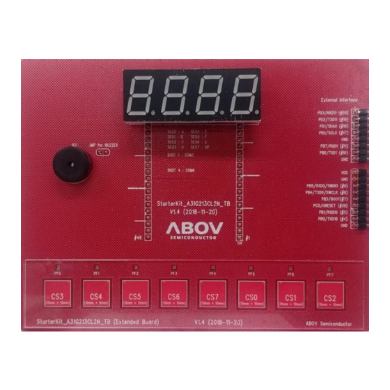
A31G213CLN Shield Board Quick Start Guide 2. User requirements User requirements Hardware 2.1.1 Starter Kit Figure 1. A31G213CLN Starter Kit Board (Hardware) 2.1.2 Shield Board Figure 2. A31G213CLN Shield Board (Hardware) -
Page 6: Software
2. User requirements A31G213CLN Shield Board Quick Start Guide Software Keil complier (uVision5) Keil MDK5 software pack (including Starter Kit sample code) or EVK software Figure 3. Compiler (Software) Reference documents Starter Kit Quick Guide Starter Kit HW Manual Starter Kit Schematic Product User’s Manual... -
Page 7: System Requirements
A31G213CLN Shield Board Quick Start Guide 2. User requirements System requirements Windows PC (7, 8, 10) USB mini-B type cable Figure 5. Window PC and Mini-B Cable ABOV website For detailed information about corresponding software and documents, you can visit our website at https://www.abovsemi.com. -
Page 8: Building And Running Project (Shield Board)
3. Building and running project (Shield Board) A31G213CLN Shield Board Quick Start Guide Building and running project (Shield Board) Running application code makes it easier to start the Shield Board. Following the steps below: Step 1. Prepare the Starter Kit and Shield Board Step 2. -
Page 9: Prepare The Starter Kit And Shield Board
Pin headers connected to MCU C. LED, switches and jumpers to check input/output, reset, and debugger pins A-Link (CMSIS-DAP/UART) board configuration A-Link for programming and debugging with ABOV 32-bit MCU(connected to USB port of UART support Figure 7. Starter Kit B/D... -
Page 10: Hardware Components Of The Shield Board
3. Building and running project (Shield Board) A31G213CLN Shield Board Quick Start Guide 3.1.2 Hardware components of the Shield Board Table 1. Shield Board Description Function Description Remark CS0 ~ CS7 User SW Touch Only Pin Touch Indicator LED User SW... -
Page 11: Set Up The Starter Kit And Shield Board
A31G213CLN Shield Board Quick Start Guide 3. Building and running project (Shield Board) Set up the Starter Kit and Shield Board 3.2.1 Set jumpers to control the Starter Kit The Starter Kit uses USB power-① Choose 3.3V and 5.0V (check the maximum operation voltage by referring to the specification sheet). -
Page 12: Connect To Starter Kit To Use Shield Board
3. Building and running project (Shield Board) A31G213CLN Shield Board Quick Start Guide 3.2.2 Connect to Starter Kit to use Shield Board Connect a header socket of the Shield Board and a header pin of the Starter Kit board as shown in Figure 10. -
Page 13: Connect The Starter Kit To Your Pc
A31G213CLN Shield Board Quick Start Guide 3. Building and running project (Shield Board) Connect the Starter Kit to your PC 3.3.1 PC connection via USB on the Starter Kit Connect the USB 2.0 (micro-B type) cable to the Starter Kit as shown in Figure 11. -
Page 14: Figure 12. Usb Composite Device At Device Manager
3. Building and running project (Shield Board) A31G213CLN Shield Board Quick Start Guide When the A-Link is connected, USB Composite Device in Device Manager is highlighted. A-Link is one of the Universal Serial Bus(USB) controllers’ class and does not require driver installation on Microsoft Windows. -
Page 15: Stks Practice
A31G213CLN Shield Board Quick Start Guide 3. Building and running project (Shield Board) STKS Practice 3.4.1 Compile with Keil uVision5 for C51 Install “Keil uVision5 for C51”. Open the provided project file (A96T418Proj.uvmpw). Figure 13. Execute Keil uVision5 for C51 Build the project. -
Page 16: Download And Debugging With A-Link
3. Building and running project (Shield Board) A31G213CLN Shield Board Quick Start Guide 3.4.2 Download and Debugging with A-Link Connection Click ① (Start/Stop Debugging Session). Check ② (Erase-Program-Verify). Figure 15. Download and Debugging with A-Link Run (Start Code Execution). Figure 16. Run (Start Code Execution) -
Page 17: Figure 17. Touch And Display
A31G213CLN Shield Board Quick Start Guide 3. Building and running project (Shield Board) A buzzer sounds when a touch is recognized. The touch indicator LED lights up during touch recognition. C. Display on LED-Segment with the rules of 0001(CS0), 0002(CS1), 0004(CS2), 0008(CS3), 0010(CS4). -
Page 18: Library Description
3. Building and running project (Shield Board) A31G213CLN Shield Board Quick Start Guide Library description 3.5.1 user.h #define _DBG_MSG_EN X — If you monitor the touch data with Smart-Key, set X=1, otherwise set X=0. Touch CH activation — Set ‘1’ for active CH and ‘0’ for inactive CH. -
Page 19: Main.c
A31G213CLN Shield Board Quick Start Guide 3. Building and running project (Shield Board) 3.5.2 main.c Init_Library (void) Initialize library variables. This function must be called before using the library API(ts_xx, led_xx, dgb_xx, .ut_xx). ts_Set_OpMode (unsigned char opMode) ts_Set_OpMode (NORMAL_MODE) In this mode, the parasitic capacitance value for each channel is not adjusted. -
Page 20: Figure 20. Sensitivity For Each Channel In Adjust Mode
3. Building and running project (Shield Board) A31G213CLN Shield Board Quick Start Guide ts_Set_OpMode (ADJUST_MODE) In this mode, the parasitic capacitance value for each channel is adjusted. ▪ Sensitivity for each channel is similar. ▪ Since the sensitivity is similar, a common threshold can be applied. -
Page 21: Figure 21. Change Of Touch Data According To Sum_Count
A31G213CLN Shield Board Quick Start Guide 3. Building and running project (Shield Board) ts_Set_SumCount (unsigned char sumCnt) Set values of the SUM_COUNT register. SUM_COUNT determines the number of consecutive sensing times for a channel. C. SUM_COUNT can act as a low pass filter, but it has the disadvantage that the sensing time becomes longer. -
Page 22: Figure 22. Base-Line Trace Parameters
3. Building and running project (Shield Board) A31G213CLN Shield Board Quick Start Guide Ts_Set_BaseTrace (unsinged char traceStep, unsigned int traceDelay) traceStep determines how much to follow at a time. traceDelay determines the period of time to trace. Figure 22. Base-Line Trace Parameters ts_Set_ReleasRate (unsinged char relRate) This function set the level for key-release judgement. -
Page 23: Figure 24. Reverse Situation Parameters
A31G213CLN Shield Board Quick Start Guide 3. Building and running project (Shield Board) ts_Set_ReverseRate (unsigned char revRate) This function set the level for key reverse situation (rawdata>basedata+α) judgement. Key reverse situation level is revRate % of threshold. ts_Set_ReverseTime (unsigned char revTime) This function set the reverse holding time (unit: ms). -
Page 24: Figure 25. Debounce Count
3. Building and running project (Shield Board) A31G213CLN Shield Board Quick Start Guide 10. ts_Set_Debounce (unsigned char debounce_n_det, unsigned char debounce_n_rel) Debounce is used to remove glitch noise. If the debounce count is too large, it takes a lot of time for touch recognition and release recognition, so you need to set the appropriate value. -
Page 25: Figure 27. Touch Key Value Assignment
A31G213CLN Shield Board Quick Start Guide 3. Building and running project (Shield Board) 12. unsigned long ts_Get_Key(void) This function returns the current touch key value (32bit). Bits are assigned sequentially from the lowest channel number among the activated keys. C. If no channel is recognized, 0 is returned. -
Page 26: Library Usage Example
3. Building and running project (Shield Board) A31G213CLN Shield Board Quick Start Guide 3.5.3 Library usage example user.h Figure 28. user.h #include in main.c Figure 29. #include in main.c... -
Page 27: Figure 30. Main() In Main.c
A31G213CLN Shield Board Quick Start Guide 3. Building and running project (Shield Board) main() Figure 30. main() in main.c... -
Page 28: Revision History
Revision history A31G213CLN Shield Board Quick Start Guide Revision history Date Version Description 20.06.29 1.00 Document created... - Page 29 ABOV Semiconductor ("ABOV") reserves the right to make changes, corrections, enhancements, modifications, and improvements to ABOV products and/or to this document at any time without notice. ABOV does not give warranties as to the accuracy or completeness of the information included herein. Purchasers should obtain the latest relevant information of ABOV products before placing orders.
Need help?
Do you have a question about the A31G213CLN and is the answer not in the manual?
Questions and answers