Lumel RE92 User Manual
Dual loop controller 96 x 96 mm
Hide thumbs
Also See for RE92:
- User manual (118 pages) ,
- User manual (180 pages) ,
- User manual (67 pages)
Table of Contents
Advertisement
Available languages
Available languages
Quick Links
Advertisement
Table of Contents

Related Manuals for Lumel RE92


Summary of Contents for Lumel RE92
- Page 1 DWUKANAŁOWY REGULATOR 96 x 96 mm DUAL LOOP CONTROLLER 96 x 96 mm RE92 INSTRUKCJA OBSŁUGI SZYBKI START USER’S MANUAL QUICK START Pełna wersja instrukcji dostępna na Zeskanuj mnie Zeskanuj kod Scan the code Full version of user’s manual available at...
- Page 2 1. WYMAGANIA PODSTAWOWE, BEZPIECZEŃSTWO UŻYTKOWANIA W zakresie bezpieczeństwa użytkowania regulator odpowiada wymaganiom normy PN-EN 61010-1. Uwagi dotyczące bezpieczeństwa: montażu i instalacji połączeń elektrycznych powinna dokonać osoba z uprawnieniami do montażu urządzeń elektrycznych, przed załączeniem regulatora należy sprawdzić poprawność połączeń, przed zdjęciem obudowy regulatora należy wyłączyć jego zasilanie i odłączyć...
-
Page 3: Podłączenia Elektryczne
Rys. 1. Mocowanie regulatora Wymiary regulatora przedstawiono na rys. 2. 76,7 Rys. 2. Wymiary regulatora 2.2. Podłączenia elektryczne Patrz str. 26. -
Page 4: Rozpoczęcie Pracy
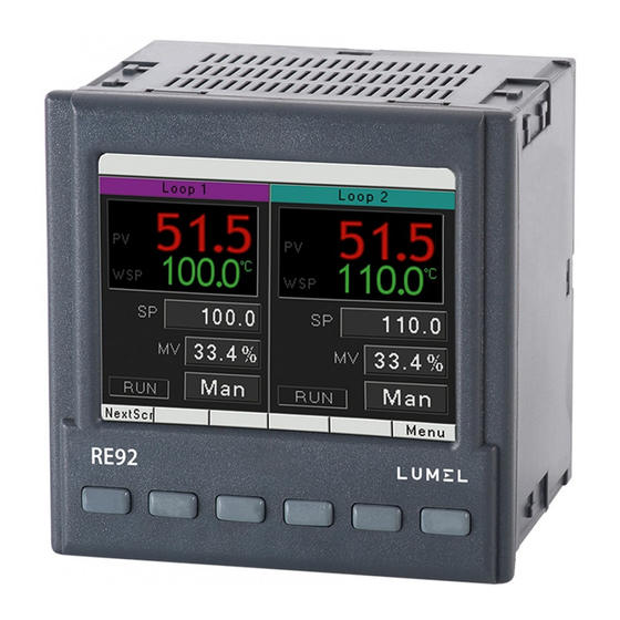
3. ROZPOCZĘCIE PRACY Po załączeniu zasilania regulator wyświetla logo a następnie przechodzi do trybu normalnej pracy. 4. URUChOMIENIE REGUlATORA 4.1. Pasek informacyjny Na pasku informacyjnym pokazany jest stan wyjść, wejść binarnych oraz zegar czasu rzeczywistego. Gdy wyjścia oraz wejścia binarne są aktywne są wyświetlone kolorem czarnym, nieaktywne są wyświetlone kolorem jasnoszarym. Stan wyjść, wejść binarnym oraz zegar może być ukryty. - Page 5 4.2. Oznaczenia przycisków Przyciski regulatora w zależności od miejsca obsługi mogą pełnić różną funkcje. Opis funkcji jest w pasku na dole ekranu. Jeżeli nie ma opisu oznacza to, że przycisk w danym momencie jest nieaktywny. Na rysunku 5 pokazane jest przykładowe oznaczenie przycisków. Funkcja Funkcja Funkcja Funkcja Funkcja Funkcja przycisku 4 przycisku 5 przycisku 6 przycisku 2 przycisku 3 przycisku 1 Rys. 5. Przykładowe oznaczenie przycisków 4.3. Tryb edycji Zmiana wartości w polu edycyjnym.
- Page 6 Użycie pola typu przycisk. W celu użycia pola tego typu (np. start/ stop regulacji) należy nacisnąć przycisk Edycja , zostanie wtedy podświetlone pierwsze pole z listy na żółto. Następnie przyciskami , , należy wybrać pole typu przycisk. Po naciśnięciu przycisku Akcja zosta- nie wykonana funkcja odpowiednia do określonego przycisku. Przycisk OK Rys. 7. Użycie pola typu przycisk...
- Page 7 4.4. Menu kontekstowe Po naciśnięciu przycisku KontstM dostępne jest menu kon- tekstowe. Pozwala ono na szybkie wywołanie danej funkcji. Rys. 8. Menu kontekstowe 5. KONfIGURACjA REGUlATORA 5.1. Hasło dostępu do menu W celu przejścia do konfiguracji regulatora, należy z poziomu widoku ekranów wybrać przycisk Menu . Pojawi się okno wyboru użytkownika oraz hasła dostępu. Przy pierwszym uruchomieniu istnieje tylko użyt- kownik [Admin], oraz nie ma ustawionego hasła. Możliwe jest ustawie- nie czterech użytkowników o różnych prawach dostępu. Użytkownik [Admin] ma wszystkie prawa, dla innych użytkowników można je odpo- wiednio ustawić. Prawa ustawiane dla użytkownika wybiera się menu Bezpieczeństwo g...
- Page 8 Przycisk Przycisk Przycisk Przycisk Menu Przycisk...
- Page 9 5.2. Matryca programowania MENU Wejście analogowe 1 Wejścia Wejście analogowe 2 Wejście analogowe 3 Wyjście 1 Wyjścia Wejście binarne 1 Wyjście 2 Wejście binarne 2 Wyjście 3 Wejście binarne 3 Wyjście 4 Modb.Wej. binarne 1 Wyjście 5 Modb.Wej. binarne 2 Wyjście 6 Modb.Wej.
-
Page 10: Dane Techniczne
6. DANE TEChNICZNE Wejście 1 i 2 Sygnały wejściowe oraz zakresy pomiarowe Tablica 1 Typ czujnika Norma Zakres Pt100 -200...850 °C -328...1562 °f 0,2% PN-EN Pt500 -200...850 °C -328...1562 °f 0,2% 60751:2009 Pt1000 -200...850 °C -328...1562 °f 0,2% Ni100 -60...180 °C -76...356 °f 0,2% Ni1000 -60...150 °C -76...302 °f 0,2% Cu100... - Page 11 Błędy dodatkowe: - od kompensacji automatycznej temperatury spoiny odniesieni 2C - od kompensacji automatycznej rezystancji przewodów dla termorezy- storów 0,3C Natężenie prądu płynącego przez czujnik termorezystancyjny: 0,22 mA Czas pomiaru:0,25 s Rezystancja wejściowa: dla wejścia napięciowego: 100 k; dla wejścia prądowego: 10 Wykrywanie błędu w obwodzie pomiarowym: - termoelement, Pt100, Pt1000 przekroczenie zakresu pomiarowego - 010 V powyżej 11 V - 05 V powyżej 5,5 V - 020 mA powyżej 22 mA - 420 mA poniżej 1 mA i powyżej 22 mA Wejście 3 (zależne od pola wejście 3 w kodzie wykonań) Błąd Typ czujnika Zakres...
- Page 12 Rodzaje wyjść 3…6: przekaźnikowe beznapięciowe - styk zwierny, obciążalność 2 A/230 V a.c. Rodzaje wyjść analogowych 1A i 2A: 1 k - analogowe napięciowe 0…10 V przy R 500 - analogowe prądowe 0…20 mA, 4…20 mA przy R Sposób działania wyjść: odwrotne - dla grzania; wprost - dla chłodzenia Błąd wyjść analogowych: 0,5% zakresu Interfejs cyfrowy RS-485: protokół: Modbus; prędkość transmisji: 4800, 9600, 19200, 38400, 57600, 115200 bit/s; tryb RTU – 8N2, 8E1, 8O1, 8N1; adres: 1…247; maksymalny czas odpowiedzi 500 ms Interfejs cyfrowy Ethernet: protokół wymiany danych Modbus TCP slave, FTP serwer Zasilanie przetworników obiektowych 24V d.c. 5 %, max.: 30 mA Znamionowe warunki użytkowania: – napięcie zasilania: 85…253 V a.c./d.c. –...
- Page 13 7. KOD WYKONAŃ Rodzaje wykonań i sposób zamawiania Tablica 2 RE92 X X X X X Wejście 3: brak prądowe: 0/4...20 mA napięciowe: 0...5/10 V potencjometryczne: 100/ 1000 Ω Wyjście 1 i 2: 2 przekaźniki 2 wyjścia binarne 0/5 V Wyjścia analogowe:...
-
Page 14: Controller Installation
1. BASIC REQUIREMENTS, OPERATIONAl SAfETY In the safety service scope, the controller meets to requirements of the EN 61010-1 standard. Observations Concerning the Operational Safety: All operations concerning transport, installation, and commissioning as well as maintenance, must be carried out by qualified, skilled personnel, and national regulations for the prevention of accidents must be observed. -
Page 15: Electrical Connections
Fig.1 Controller fixing in the panel Controller overall dimensions are presented on the fig. 2. 76,7 Fig. 2. Controller dimensions. 2.2. Electrical Connections See page 26. -
Page 16: Starting To Work
3. STARTING TO WORK After turning a supply on, the controller displays logo and then moves to the normal operational mode. 4. STARTING ThE CONTROllER 4.1. Information bar Information bar displays the state of outputs, binary inputs and real-time clock. When active binary outputs and inputs are displayed in black, inactive ones are displayed in light grey color. State of the outputs, binary inputs and real-time clock can be hidden. -
Page 17: Button Markings
4.2. Button markings Depending on the service location, controller buttons can perform diffe- rent functions. Functions are described in the bar on the bottom of the screen. If the button lacks description, it is inactive at the moment. Fig. 5 shows an example of the button marking. Function Function Function Function Function Function of button 5 of button 4 of button 6 of button 1 of button 3 of button 2 Fig. - Page 18 Using the button type field. To use such field (e.g. start/stop control), press the Edit button; the first item in the list will be highlighted in yellow. Then use the , , buttons to select the button type field. Pressing the Exec button performs a fun- ction appropriate to the given button. Button Exec Fig. 7. Using the button type field.
-
Page 19: Context Menu
4.4. Context menu Pressing the ContxtM button displays the context menu. This menu allows for quick access to a given feature. Fig. 8. Context menu 5. CONTROllER CONfIGURATION 5.1. Menu access password To switch to the controller configuration from the screen display level, choose the Menu button. Use selection and access password window will appear. On the first run, there is only one user [Admin] with no set password. It is possible to create four users with different access rights. User [Admin] has all the rights, and can set them for the... - Page 20 Button Button Button Button Button Menu...
-
Page 21: Programming Matrix
5.2. Programming matrix MENU Inputs Analog input 1 Analog input 2 Outputs Output 1 Analog input 3 Output 2 External input 1 Output 3 External input 2 Output 4 Binary input 1 Output 5 Binary input 2 Output 6 Binary input 3 Analog output 1 Modb. -
Page 22: Technical Data
6. TEChNICAl DATA Input 1 and 2 Input signals and measuring ranges Table 1 Intrin- Sensor type Standard Range error Pt100 -200...850 °C -328...1562 °f 0.2% Pt500 -200...850 °C -328...1562 °f 0.2% 60751:2009 Pt1000 -200...850 °C -328...1562 °f 0.2% Ni100 -60...180 °C -76...356 °f 0.2% Ni1000 -60...150 °C -76...302 °f... - Page 23 0...100 0.2% ± 1 digit potentiometric 1000 0...1000 Measurement time: 0.25 s Input resistance: for voltage input 100 k; for current input 50 Setting range of controller parameters: see Table 1 (see full version of service manual, available at www.lumel.com.pl) Binary inputs 1…3 voltageless: shorting resistance 10 k; opening out resistance 100 k Output 1 and 2 types: - relay voltageless: NOC contact, load capacity 2 A/230 VAC - voltage transistor 0/5 V, max load capacity 40 mA Output 3…6 types: - relay voltageless NOC contact, load capacity 2 A/230 VAC Analog output types 1A and 2A: –...
- Page 24 Way of output operation: reverse - for heating; direct - for cooling Analog outputs error: 0.5% of the range digital interface RS-485: protocol Modbus; baud rate 4800, 9600, 19200, 38400,57600, 115200 bit/s; mode RTU – 8N2, 8E1, 8O1, 8N1; address 1…247; maximal response time 500 ms digital interface Ethernet: protocol Modbus TCP slave Supply of object transducers: 24V d.c. 5 %, max.: 30 mA Rated operating conditions: – supply voltage: 85…253 V a.c./d.c. – supply voltage frequency: 40…440 Hz – ambient temperature: 0…23…50 °C – storage temperature: -20…+70 °C – relative air humidity < 85 % (no condensation) – preheating time: 30 min – operating position: any – resistance of wires connecting the resistance thermometer or thermocouple with controller < 20 / wire Power input < 16 VA Weight < 0.5 kg...
-
Page 25: Controller Ordering Code
7. CONTROllER ORDERING CODE Versions and ordering Table 2 RE92 X X X X X Input 3: none current: 0/4...20 mA voltage: 0...5/10 V potentiometric transmitter: 100/ 1000 Ω Output 1 and 2: 2 relays 2 binary outputs 0/5 V... - Page 26 SChEMATY PODłąCZEŃ ElECTRICAl CONNECTIONS Regulator ma trzy listwy rozłączne z zaciskami śrubowymi. Dwie listwy po 16 zacisków umożliwiają przyłączenie wszystkich sygnałów przewo- dem o przekroju do 2,5 mm , a dwie listwy po 10 zacisków umożliwiają przyłączenie przewodów przewodem o przekroju do 1,5 mm The controller has three separate strips with screw terminals. Two strips with 16 terminals each allow to connect all signal sources by a wire with a 2.5 mm cross-section, and two strips with 10 terminals each allow for connecting by a wire with 1.5 mm cross-section.
- Page 27 POd£¥CZENIE ZASIlANIA / ConneCting the supply zasilanie/ supply do zacisków 51, 52 należy podłączyć zasilanie zgodnie z kodem wykonań supply should be connected to the terminals 51 and 52, according to technical data POdłąCZENIE WEjśCIA 1 i 2 / ConneCtion of 1 2 input IN1, IN2- wejście 1,2 / input 1,2 OUT1, OUT2,... -wyjście 1,2,.../ output 1,2,.. termorezystor Pt100 termorezystor Pt100 w układzie w układzie 2-przewodowym 3-przewodowym thermoresistor Pt100 in 2-wire system thermoresistor Pt100 in 3-wire system...
- Page 28 wejście napięciowe 0...5/10 V wejście prądowe 0/4...20 mA voltage input 0...5/10 V current input 0/4...20 mA POdłąCZENIE WEjśCIA 3 / ConneCtion of input 3 wejście wejście prądowe wejście napięciowe potencjometryczne 0/4..20 mA 0...5/10 V potentiometric current input 0/4..20 mA voltage input 0...5/10 V input POdłąCZENIE Wyjść BINARNyCh / ConneCtion of the binary outputs odbiornik/ load load OUT6 OUT5 OUT4 OUT3 OUT2 OUT1...
-
Page 29: Connecting The Analog Outputs
load odbiornik/ load OUT2 OUT1 wyjście 1, 2 – napięciowe 0/5 V output 1 and 2 – voltage 0/5 V POd£¥CZENIE Wyjœæ ANAlOgOWyCh/ ConneCting the analog outputs wyjście 1 A – prądowe 0/4...20 mA i napięciowe 0...10 V output 1A – current 0/4...20 mA and voltage 0...10 V load odbiornik/ load load odbiornik/ load OUT1A wyjście 2 A – prądowe 0/4...20 mA i napięciowe 0...10 V output 2A – current 0/4...20 mA odbiornik/ load load and voltage 0...10 V... -
Page 30: Connecting The Rs-485 Interface
RJ-45 connector, compliant to the following standards: • EIA/TIA 568A for both connectors in strike-through connection (i.e. between RE92 and hub or switch), • EIA/TIA 568A for the first connector and EIA/TIA 568B for the second one in the cross-over connection (i.e. when connecting... -
Page 31: Recommendations For Installation
(at least 30 cm) and should be crossed only at the right angle (90 degrees). – to connect RE92 controller to the Ethernet it is recommended to use: • U/FTP – twisted pair cable with separate foil shielding for every pair, •... - Page 32 LUMEL S.A. ul. Sulechowska 1, 65-022 Zielona Góra, Poland tel.: +48 68 45 75 100, fax +48 68 45 75 508 www.lumel.com.pl Informacja techniczna: tel.: (68) 45 75 306, 45 75 180, 45 75 260 e-mail: sprzedaz@lumel.com.pl Realizacja zamówień: tel.: (68) 45 75 207, 45 75 209, 45 75 218, 45 75 341 fax.: (68) 32 55 650...
Need help?
Do you have a question about the RE92 and is the answer not in the manual?
Questions and answers