Lumel re72 series Quick Start Manual
48x48 mm
Hide thumbs
Also See for re72 series:
- User manual (96 pages) ,
- User manual & quick start (33 pages) ,
- Quick start manual (33 pages)
Table of Contents
Advertisement
Quick Links
Download this manual
See also:
User Manual
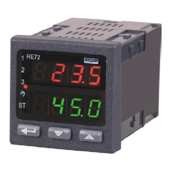
CONTROLLER
48x48 mm
RE72 TYPE
QUICK START
MANUAL
Note!
The full version of the user's manual is inserted in the
www.lumel.com.pl/en/ web site.
1. CONTROLLER SET
1. controller.................................. 1 pc
2. plug with 6 screw terminals......1 pc
3. plug with 8 screw terminals......1 pc
4. screw clamp to fix the controller
6. user's manual..............1 pc
in the panel...............................4 pcs
5. seal...........................................1 pc
7. guarantee card............1 pc
2. OPERATIONAL SAFETY
In the safety service scope, the controller meets to requirements of the
EN 61010-1 standard.
Observations concerning the operational safety:
· All operations concerning transport, installation and commissioning
as well as maintenance must be carried out by qualified, skilled
personnel, and national regulations for the prevention of accidents
must be observed.
· Before switching the controller on, one must check the correctness
of connections to the network.
· The removal of the controller casing during the guarantee contract
period causes its cancellation.
· The device is destined to be installed and used in industrial electro-
magnetic environment conditions.
· A switch or a circuit-breaker should be located near the device,
easy accessible by the operator and suitably marked.
3. FIXING WAY
Fix the controller in the panel by means of four screw clamps acc. to the
fig. 1. The panel cut-out should have 45+
x 45+
mm dimensions.
0,6
0,6
The thickness of the material from which the panel is made of cannot
exceed 15 mm.
Fig.1. Controller fixing in the panel.
4. CONTROLLER DIMENSIONS
Fig.2. Controller dimensions.
5. CONNECTION DIAGRAMS
Supply
Fig.3. Controller connection diagram
Relay output
Binary input
Current transformer input
Additional input 0/4 ... 20 mA
Transducer supply
Fig. 4. Diagram of optional controller connections
6. CONTROLLER CONFIGURATION
The controller configu-
ration can be carried
out by the free LPCon
program available on our
website
www.lumel com.pl/en/ or
through the controller
menu acc. to the user's
manual.
Transmission of the configu-
ration through the RS-485
interface
7. STARTING TO WORK
After switching the supply on, the controller carries out the display test,
re72
displays the
inscription, the program version and next, displays
measured and set point values.
A character message informing about abnormalities may appear on the
display (point 8).
Changing the set point value
One can change the set point value by pressing the
push-button. The beginning of the change is signaled by the flickering
dot on the lower display. One must accept the new set point value by
the
push-button during 30 seconds since the last pressure of
the
or
push-button, in the contrary, the old value will
be restored. The change limitation is set by SPL and SPH parameters.
Programming of controller parameters.
Press and hold down during ca 2 sec. the
push-button, what cau-
ses the enter to the programming matrix. The fig. 6 presents the transition
matrix in the programming mode. The transition between levels is carried
out by means of
or
push-buttons and the level selection
by means of the
push-button. After selecting the level, the transi-
tion
between
parameters
is
carried
out
by
means
or
push-buttons and the parameter selection by means of
the
push-button. Next, through
or
push-buttons,
one can change the setting, accepting it by the
push-button.
In order to exit from the programming matrix to the normal working mode,
one must transit between parameters and levels, until the symbol [. . .]
appears and press the
push-button.
.
8. ERROR CODES
Upper overflow of the measuring range or break in the
sensor circuit.
Down overflow of the measuring range or shorting in the
sensor circuit.
eR01
Incorrect controller configuration.
eR02
Incorrect controller configuration.
eS--
Auto-tuning ended with failure.
eRad
Input discalibrated.
Continuous output discalibrated.
eRda
eRee
Error of readout verification from the non-volatile memory.
9. TECHNICAL DATA
Input signals and measuring ranges
Sensor type
Standard
Pt100
-200...850
PN-EN
60751+A2:1997
or
Pt1000
-200...850
Fe-CuNi (J)
-100...1200
Cu-CuNi (T)
-100...400
NiCr-NiAl (K)
-100...1372
PtRh10-Pt (S)
0...1767
PN-EN
60584-1:1997
PtRh13-Pt (R)
0...1767
PtRh30-PtRh6 (B)
0...1767
NiCr-CuNi (E)
-100...1000
NiCrSi-NiSi (N)
-100...1300
GOST R 8.585-
chromel – kopel (L)
-100...800
2001
of
Linear current (I)
0...20 mA
Linear current (I)
4...20 mA
Linear voltage (U)
0...5V
Linear voltage (U)
0...10V
1)
The intrinsic error is related to measuring range: 200...1767
Intrinsic error of the real value measurement
0.2%, for resistance thermometer inputs,
0.3%, for inputs for thermocouple sensors (0.5% – for B, R, S);
0.2% 1 digit, for linear inputs
Table 1
Range
Symbol
o
o
pt1
C
-328...1562
F
o
o
C
-328...1562
F
pt10
o
o
t-,
C
-148...2192
F
o
C
-148...752
o
F
t-t
o
o
t-k
C
-148...2501.6
F
o
C
32...3212.6
o
F
t-s
o
o
t-r
C
32...3212.6
F
o
o
t-b
C
1)
32...3212.6
F
1)
o
o
t-e
C
-148...1832
F
o
o
t-n
C
-148...2372
F
o
o
t-l
C
-148...1472
F
0-20
0...20 mA
4...20 mA
4-20
0-5
0...5 V
0...10 V
0-10
o
o
C (392...3212.6
F)
Advertisement
Table of Contents

Subscribe to Our Youtube Channel
Related Manuals for Lumel re72 series


Summary of Contents for Lumel re72 series
- Page 1 1. The panel cut-out should have 45+ x 45+ mm dimensions. website 48x48 mm The thickness of the material from which the panel is made of cannot www.lumel com.pl/en/ or eR02 exceed 15 mm. Incorrect controller configuration. RE72 TYPE through the controller menu acc.
- Page 2 (continuation of point 9. Technical data) - relative air humidity < 85 % (condensation inadmissible) - preheating time 30 min Current flowing through the resistance - operating position thermometer sensor 0.22 mA - resistance of wires connecting the resistance thermometer with Measurement time 0.2 s the controller...
Need help?
Do you have a question about the re72 series and is the answer not in the manual?
Questions and answers