Table of Contents
Advertisement
Available languages
Available languages
Quick Links
Advertisement
Table of Contents

Related Manuals for Lumel RE71


Summary of Contents for Lumel RE71
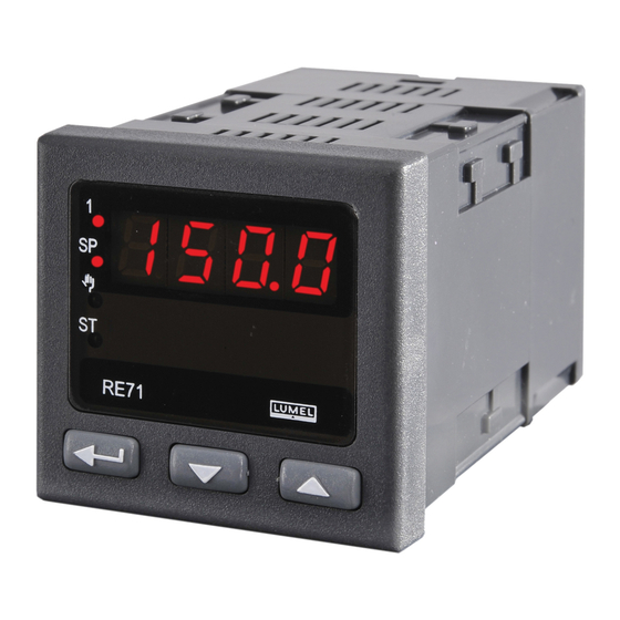
- Page 1 REGULATOR 48 x 48 mm CONTROLLER 48 x 48 mm RE71 INSTRUKCJA OBSŁUGI SZYBKI START USER’S MANUAL QUICK START Pełna wersja instrukcji dostępna na Zeskanuj mnie Zeskanuj kod Scan the code Full version of user’s manual available at www.lumel.com.pl...
- Page 2 1. WYMAGANIA PODSTAWOWE, BEZPIECZEŃSTWO UŻYTKOWANIA W zakresie bezpieczeństwa użytkowania regulator odpowiada wymaganiom normy PN-EN 61010-1. Uwagi dotyczące bezpieczeństwa: montażu i instalacji połączeń elektrycznych powinna dokonać osoba z uprawnieniami do montażu urządzeń elektrycznych, przed załączeniem regulatora należy sprawdzić poprawność połączeń, przed zdjęciem obudowy regulatora należy wyłączyć jego zasilanie i odłączyć...
-
Page 3: Podłączenia Elektryczne
Wymiary regulatora przedstawiono na rys. 2. Rys. 2. Wymiary regulatora 2.2. Podłączenia elektryczne Patrz str. 22 , rys. 3-5. -
Page 4: Rozpoczęcie Pracy
Na wyświetlaczu może być komunikat znakowy informujący o nieprawidłowościach (tablica 4 - patrz pełna wersja instrukcji obsługi, dostępna na www.lumel.com.pl). Fabrycznie ustawiony jest algorytm regulacji załącz-wyłącz z histerezą podaną w tablicy 2 (patrz pełna wersja instrukcji obsługi, dostępna na www.lumel.com.pl). - Page 5 4. OBSłUGA Obsługa regulatora jest przedstawiona na rys. 7...
- Page 6 . W celu zmiany nasta- wy parametru należy postępować wg punktu 6.3 (patrz pełna wersja instrukcji obsługi, dostępna na www.lumel.com.pl). W celu wyjścia z wybranego poziomu należy przechodzić pomiędzy parametrami aż po- jawi się symbol [. . .] i wcisnąć przycisk .
- Page 7 4.2. Matryca programowania patrz pełna wersja instrukcji obsługi, dostępna na www.lumel.com.pl Rys. 8. Matryca programowania...
- Page 8 4.3. Zmiana nastawy Zmianę nastawy parametru rozpoczyna się po naciśnięciu przy- cisku podczas wyświetlania nazwy parametru. Przyciskami dokonuje się wyboru nastawy, a przyciskiem akceptuje. Anulowanie zmiany następuje po jednoczesnym naciśnięcie przycisków lub automatycznie po upływie 30 sekund od ostatniego naciśnięcia przycisku. Sposób zmiany nastawy pokazano na rys. 9. Rys.
-
Page 9: Dane Techniczne
5. DANE TECHNICZNE Sygnały wejściowe oraz zakresy pomiarowe Tablica 1 Typ czujnika Zakres Błąd podstawowy czujnik termorezystancyjny (wg PN-EN 60751+A2:1997), prąd pomiarowy 0,25 mA -50...100 ±0,8 0...250 ±1,3 Pt100 0...600 ±3,0 czujnik termolektryczny typu J (wg PN-EN 60584-1:1997) 0...250 ±2,0 Fe-CuNi 0...600 ±3,0... - Page 10 Znamionowe warunki użytkowania: - napięcie zasilania: 230 V a.c. ±10% - częstotliwość napięcia zasilania: 50/60 Hz - temperatura otoczenia: 0…23…50 °C - temperatura przechowywania: -20…+70 °C - wilgotność względna powietrza < 85 % (bez kondensacji pary wodnej) - zewnętrzne pole magnetyczne < 400 A/m - czas wstępnego nagrzewania: 30 min - położenie pracy: dowolne Pobór mocy <...
- Page 11 6. KOD WYKONAŃ Tablica 2 Regulator RE71 Wejście: termorezystor Pt100 (-50...100°C) ....01 termorezystor Pt100 (0...250°C) ....02 termorezystor Pt100 (0...600°C) ....03 termoelement J (Fe-CuNi) (0...250°C) ....04 (0...600°C) ....05 termoelement J (Fe-CuNi) (0...900°C) ....06 termoelement J (Fe-CuNi) (0...600°C) ....
-
Page 12: Basic Requirements, Operational Safety
1. BASIC REQUIREMENTS, OPERATIONAL SAFETY In the safety service scope, the controller meets to requirements of the EN 61010-1 standard. Observations Concerning the Operational Safety: All operations concerning transport, installation, and commissioning as well as maintenance, must be carried out by qualified, skilled personnel, and national regulations for the prevention of accidents must be observed. -
Page 13: Electrical Connections
Fig.1 Controller fixing in the panel Controller overall dimensions are presented on the fig. 2. Fig. 2. Controller dimensions. 2.2. Electrical Connections See page 22, fig. 3-5. -
Page 14: Starting To Work
A character message informing about abnormalities may appear on the display (table 4 - see full version of service manual, available at www.lumel.com.pl). The On-Off control algorithm with hysteresis gi- ven in the table 2 (full version of service manual) is set by the manufac- turer. - Page 15 4. SERVICE The controller service is presented on the fig. 7...
- Page 16 Some controller parameters cannot be visible – it depends on the cur- rent configuration. The table 1 (see full version of service manual, available at www.lumel.com.pl) includes the description of parameters. The return to the normal wor- king mode follows automatically after 30 seconds since the last button...
-
Page 17: Programming Matrix
4.2. Programming Matrix Fig. 8. Programming matrix... -
Page 18: Setting Change
4.3. Setting Change The change of parameter setting begins after pressing the button during the display of the parameter name. The setting choice is carried out through buttons, and accepted by the button. The change cancellation follows after the simultaneous pressure buttons or automatically after 30 sec since the last push pressure. -
Page 19: Technical Data
5. TECHNICAL DATA Input Signals Input signals and measuring ranges Table 1 Sensor type Range Basic error Resistance thermometer (acc. to EN 60751:2009), measuring current 0.25mA - 50...100 ±0.8 0...250 ±1.3 Pt100 * 0...600 ±3.0 Thermocouple of J type (acc. to EN 60584-1:1997) 0...250 ±2.0 Fe-CuNi... - Page 20 Rated operating conditions: - supply voltage: 230 V a.c. ±10% - frequency: 50/60 Hz - ambient temperature: 0…23…50 °C - storage temperature: -20…+70 °C - relative air humidity < 85 % (condensation inadmissible) - external magnetic field < 400 A/m - preheating time: 30 min - operating position: any Power input: <...
-
Page 21: Controller Version Codes
6. CONTROLLER VERSION CODES Table 2 Temperature Controller RE71 Input: RTD Pt100 (-50...100°C) ....01 RTD Pt100 (0...250°C) ....02 (0...600°C) ....03 RTD Pt100 (0...250°C) ....04 thermocouple J (Fe-CuNi) thermocouple J (Fe-CuNi) (0...600°C) ....05 thermocouple J (Fe-CuNi) (0...900°C) .... - Page 22 SCHEMATY PODłąCZEŃ ELECTRICAL CONNECTIONS Regulator dwie listwy rozłączne zaciskami śrubowymi. Jedna listwa umożliwia przyłączenie zasilania i wyjścia przewodem o przekroju do 2,5 mm druga listwa umożliwia przyłączenie sygnałów wejściowych przewodem do 1,5 mm Make electrical connections to terminal strip and next, insert strips into the con- troller sockets.
-
Page 23: Installation Recommendations
2.3. Zalecenia instalacyjne W celu uzyskania pełnej odporności regulatora na zakłócenia elektro- magnetyczne powinno się przestrzegać następuj¹cych zasad: – nie zasilać regulatora z sieci w pobliżu urządzeń wytwarzających zakłócenia impulsowe i nie stosować wspólnych z nimi obwodów uziemiaj¹cych, – stosować filtry sieciowe, –... - Page 24 LUMEL S.A. ul. Sulechowska 1, 65-022 Zielona Góra, Poland tel.: +48 68 45 75 100, fax +48 68 45 75 508 www.lumel.com.pl Informacja techniczna: tel.: (68) 45 75 306, 45 75 180, 45 75 260 e-mail: sprzedaz@lumel.com.pl Realizacja zamówień: tel.: (68) 45 75 207, 45 75 209, 45 75 218, 45 75 341 fax.: (68) 32 55 650...
Need help?
Do you have a question about the RE71 and is the answer not in the manual?
Questions and answers