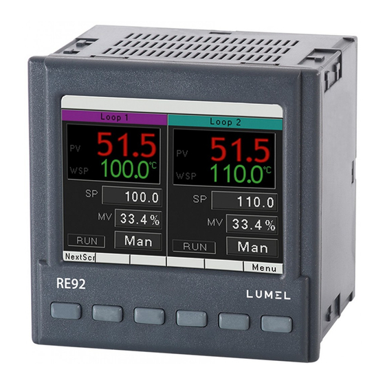
Lumel RE92 User Manual
Dual loop controller
Hide thumbs
Also See for RE92:
- User manual (118 pages) ,
- User manual (180 pages) ,
- User manual (33 pages)
Table of Contents
Advertisement
Quick Links
Download this manual
See also:
User Manual
Advertisement
Table of Contents

Related Manuals for Lumel RE92


Summary of Contents for Lumel RE92
-
Page 2: Table Of Contents
RE92-09C User's Manual Contents: 1. Introduction ..........................3 1.1. Purpose ..........................3 1.2. Controller properties ......................3 2. Controller set .......................... 3 3. Basic requirements, operational safety ................... 4 4. Installation ..........................4 4.1. Controller installation ......................4 4.2. Electrical connections ......................5 4.3. -
Page 3: Introduction
User's Manual 1. Introduction 1.1. Purpose Two-loop RE92 controller used to control temperature and other physical values (e.g. pressure, humidity, flow level). It can control two objects independently or control two physical values in one object (e.g. two-chamber furnaces). 1.2. Controller properties RE92 controller is characterized by the following features: ... -
Page 4: Basic Requirements, Operational Safety
RE92-09C User's Manual Complete set of the controller includes: 1. controller ..........1 pc 2. seal ............1 pc 3. holders to fix the meter in the panel ..4 pcs 4. plug with 16 screw terminals ....2 pcs 5. -
Page 5: Electrical Connections
RE92-09C User's Manual Fig. 2. Controller dimensions. 4.2. Electrical connections The controller has three separate strips with screw terminals. Two strips with 16 terminals each allow to connect all signal sources by a wire with a 2.5 mm cross-section, and two strips with 10 terminals each allow for connecting by a wire with 1.5 mm... - Page 6 RE92-09C User's Manual Connecting the supply Supply supply should be connected to the terminals 51 and 52, according to technical data 52 51 Connection of 1 and 2 entry IIN2 jumper jumper Pt100 Pt100 Pt1000 thermoresistor Pt100 in 2-wire thermoresistor Pt100 in 3-wire...
- Page 7 RJ-45 connector, compliant to the following standards: • EIA/TIA 568A for both connectors in strike-through connection (i.e. between RE92 and hub or switch), • EIA/TIA 568A for the first connector and EIA/TIA 568B for the second one in the cross-over connection (i.e. when connecting...
-
Page 8: Recommendations For Installation
(at least 30 cm) and should be crossed only at the right angle (90 degrees). ─ to connect RE92 controller to the Ethernet it is recommended to use: U/FTP – twisted pair cable with separate foil shielding for every pair, ... -
Page 9: Starting The Controller
RE92-09C User's Manual 6. Starting the controller 6.1. Information bar Information bar displays the state of outputs, binary inputs and real-time clock. When active binary outputs and inputs are displayed in black, inactive ones are displayed in light grey color. -
Page 10: Screen With Programming Control
RE92-09C User's Manual 6.4. Screen with programming control Fig. 7. Screen with programming control 6.5. Change of displayed screens Screens Button allows for switching between two loops - first and second. Fig. 8 presents the change of the displayed screens for the controller with fixed set-point control. -
Page 11: Edit Mode
RE92-09C User's Manual 6.6. Edit mode Changing the value in the edit field. Edit To change the value in the edit field (i.e. set value), press the button; the first field of the list will by highlighted in yellow. Then use the , , and buttons to select the edit field Change button, use ... -
Page 12: Context Menu
RE92-09C User's Manual Button: Fig. 10. Using the button type field. 6.7. Context menu ContxtM Pressing the button displays the context menu. This menu allows for quick access to a given feature. Fig. 11. Context menu... -
Page 13: Controller Configuration
RE92-09C User's Manual 7. Controller configuration 7.1. Menu access password Menu To switch to the controller configuration from the screen display level, choose the button. Use selection and access password window will appear. On the first run, there is only one user ] with no set password. - Page 14 RE92-09C User's Manual Programming matrix MENU Analog input 1 Inputs Analog input 2 Analog input 3 Binary input 1 Binary input 2 Binary input 3 Output 1 Outputs Output 2 Output 3 Output 4 Output 5 Output 6 Analog output 1...
-
Page 15: Parameters Description
RE92-09C User's Manual 7.2. Parameters description The list of parameters is presented in the table 1. List of configuration parameters Table 1 Symbol Parameter modification range Factory Parameter name setting sensors linear input parameter Inputs Analog input 1 Pt100 : thermoresistor Pt100... - Page 16 RE92-09C User's Manual Symbol Parameter modification range Factory Parameter name setting sensors linear input parameter Off: filter off 0.2: time constant 0.2 s 0.5: time constant 0.5 s 1: time constant 1 s 2: time constant 2 s Filter 5: time constant 5 s...
- Page 17 RE92-09C User's Manual Symbol Parameter modification range Factory Parameter name setting sensors linear input parameter Binary input 1 none: none Stop: stop automatic control (response to a level) ManualOp: switching to manual operation (response to a level) SP+1: switching to subsequent SP...
- Page 18 RE92-09C User's Manual Symbol Parameter modification range Factory Parameter name setting sensors linear input parameter None: none Heating: heating Cooling: cooling Opening: valve opening Function Closing: valve closing None Alarm: alarm Event Prg: progr. control event CascadeSlv: signal of the slave loop with...
- Page 19 RE92-09C User's Manual Loop 1 Inputs Inp1: input 1 Inp2: input 2 Inp3: input 3 Measuring value Inp1+Inp2: input 1 + input 2 Inp1+Inp3: input 1 + input 3 Inp2+Inp3: input 2 + input 3 Val for Inp1 -10.00...10.00 1.00 Val for Inp2 -10.00...10.00...
- Page 20 RE92-09C User's Manual Symbol Parameter modification range Factory Parameter name setting sensors linear input parameter Control Off: control off Heating: heating-type control Cooling: cooling-type control Control type Heat-Cool: heating-cooling control Heating: Valve: step-by-step valve control Feedback valve.: step-by-step feedback valve...
- Page 21 RE92-09C User's Manual Symbol Parameter modification range Factory Parameter name setting sensors linear input parameter Gain Scheduling Off: off GS Type SP: switched according to set value Set: fixed set 2: 2 PID sets used GS level no. 3: 3 PID sets used...
- Page 22 RE92-09C User's Manual Symbol Parameter modification range Factory Parameter name setting sensors linear input parameter Ramp rate 0.1...999.9 Deviation -9999...99999 Event 1 Event 2 Event 3 Event 4 Event 5 Event 6 PID1 PID2 PID set PID3 PID1 PID4 Segment 2...
- Page 23 RE92-09C User's Manual Symbol Parameter modification range Factory Parameter name setting sensors linear input parameter Alarm 6 as Alarm 1 Modbus Address 4800 bps 9600 bps 19.2 kbps Speed 9600 bps 38.4 kbps 57.6 kbps 115.2 kbps RTU 8N2...
-
Page 24: Inputs And Outputs Of The Controller
– default setting and extent of the changes depends on input 3 field in the ordering code – shown for Ethernet version 8. Inputs and outputs of the controller RE92 controller is fitted with two measuring inputs, one additional input (optional) and three binary inputs. 8.1. Measuring inputs1 Input 1 is the source of the measured value used for control and alarms. -
Page 25: Measuring Input 2
RE92-09C User's Manual For the linear inputs, set the indication for the lower and upper analog input threshold through the [ ] and [ ] parameter. LowScale HighScale Correction of the indicated measuring value is done through the [ ] parameter. -
Page 26: Controller Outputs
If one channel is assigned to more than one binary input, than for each of them must be set a different function. 9. Controller outputs RE92 controller has six binary outputs and two analog outputs: current and voltage (optional). 9.1. Controlling outputs [Heat] function output is a reverse output. It is used during control, when the increase of the controlled signal causes the value of output signal to drop. -
Page 27: Alarm Outputs
RE92-09C User's Manual 9.2. Alarm outputs Alarm configuration is done in two steps: 1. In [ ] submenu - where k=1...6 (menu: Outputs): Output k select the number of loop or input allocated to the output being configured –... -
Page 28: Signal Outputs
RE92-09C User's Manual Retransmission output parameters can be found in menu: Outputs Analog output 1 and Outputs Analog output 2. Picture 14 shows method of transforming the retransmitted signal into proper analog output signal. Fig. 14. Transformation of the signal to be retransmitted... -
Page 29: Control Types
RE92-09C User's Manual Example 2: To control the mean of input 1 and input 2 signals, enter: ] = [ ] = 0.5 ] = 0.5. Inp1+Inp2 Coeff. for Inp 1 Coeff. for Inp 2 10.2. Control types Heating-type control ... - Page 30 RE92-09C User's Manual Fig.16. Three-step step-by-step control with no feedback The principle of the algorithm shown in Fig. 16 is based on conversion of changing the control signal to the relay opening / closing time referred to the full opening / closing time.
- Page 31 RE92-09C User's Manual Loop 1 rescaling to loop 2 range control output Loop 2 Fig. 17.Cascade control First loop should be set to PID control to select the cascade control. In the second loop the parameter [Control type] in menu: Loop 2Control should be set to [Cascade]. For rescaling the master loop output set the parameters [Casc.SO Lo] and [Casc.SO Hi] in menu:...
-
Page 32: Control Range
RE92-09C User's Manual PID4 GS Level 3-4 PID3 GS Level 2-3 PID2 GS Level 1-2 PID1 czas Fig.18."Gain Scheduling" Fig. 19. "Gain Scheduling" switched over for each switched over from SP segment in the programmed control. 10.3. Control range Control range is defined by [ ] and [ ] parameters. - Page 33 RE92-09C User's Manual SMART PID algorithm When high precision of the temperature control is necessary, it is recommended to use PID algorithm. Innovative SMART PID algorithm ensures increased precision in the extended range of the control object classes. Tuning of the controller to object is achieved by manual setting of the proportional term, derivation term or difference term or automatically –...
- Page 34 RE92-09C User's Manual Auto-tuning The controller has the function to select PID settings. In most cases these settings ensure an optimal control. To begin the auto-tuning, one must select the field ST on the screen of a single loop with fixed set-point control and then press a button Exec.
- Page 35 RE92-09C User's Manual to [ ], and select the parameter [ ] between [ ] and menu: Loop xGain Scheduling GS Set PID1 PID4 The second way enables an automatic realization of the auto-tuning for all PID sets. One must set the [...
-
Page 36: Programming Control
RE92-09C User's Manual 11. Programming control 11.1. Description of the programming control parameters List of configuration parameters Table 3 [Programs] – programs defined for programming control [Program 1] - program 1 submenu [Program 20] - program 20 submenu [Prg.Conf.] - program parameters submenu... -
Page 37: Defining The Set Value Programs
RE92-09C User's Manual Parameter modification Symbol Parameter Factory range of parameter description setting sensors linear input Time: time-defined segment Accrual: accrual-defined segment Seg.Type Segment type Time Hold: set value hold End: program end Set value at the end MIN…MAX Target SP 0.0°C... - Page 38 RE92-09C User's Manual List of segment configuration parameters Table 4 [Seg.Type] = [Time] [Seg.Type] = [Rate] [Seg.Type] = [Dwell] [Seg.Type] = [End] Target SP Target SP Segment time Segment time Ramp rate Holdback Val Holdback Val Picture 22 and table 5 show an example of set value program. The program assumes that the object temperature should increase from initial temperature to 800 °C with a rate of 20 °C per...
-
Page 39: Modbus Protocol
Event 1 Events 1 on output 2: on 12. MODBUS protocol 12.1. Introduction RE92 controller is equipped with RS-485 serial interface with implemented MODBUS protocol. Summary of the RE92 controller Modbus protocol: device address: 1..247, baud rate: 4800, 9600, 19200, 38400, 57600 bit/s, 115200 bit/s ... -
Page 40: Register Map
RE92-09C User's Manual 12.3. Register map Register groups map Table 8 address range value type description 4000 – 4099 integer (16 bits) value set in the 16-bit register. value set in the two subsequent 16-bit 7000 – 7099 float (2x16 bits) - Page 41 RE92-09C User's Manual Table 10 description Input 1 measuring value out of measurement range Input 2 measuring value out of measurement range Input 3 measuring value out of measurement range Loop 1 measuring value out of measurement range Loop 2 measuring value out of measurement range Manual operation in loop 1: 1 –...
- Page 42 RE92-09C User's Manual Map of the registers from address 7100 Table 14 register ope- parameter range description address rations Type of input no. 1: 0 – thermoresistor Pt100 1 – thermoresistor Pt500 2 – thermoresistor Pt1000 3 – thermoresistor Ni100 4 –...
- Page 43 RE92-09C User's Manual register ope- parameter range description address rations Type of input no. 2: 0 – thermoresistor Pt100 1 – thermoresistor Pt500 2 – thermoresistor Pt1000 3 – thermoresistor Ni100 4 – thermoresistor Ni1000 5 – thermoresistor Cu100 6 – J type thermocouple 7 –...
- Page 44 RE92-09C User's Manual register ope- parameter range description address rations Decimal point position for input 3: 3) 4) 0…1 0 – without a decimal place 7140 0…2 1 – 1 decimal place 2 – 2 decimal places 7142 -9999…99999 Indication for the lower limit for input 3 (linear input) 7144 -9999…99999...
- Page 45 RE92-09C User's Manual register ope- parameter range description address rations Allocation of output 1: 0 – none 1 – loop 1 2 – loop 2 3 – input 1 4 – input 2 5 – input 3 0…12 7156 6 – input 1 + input 2 + input 3 7 –...
- Page 46 RE92-09C User's Manual register ope- parameter range description address rations Output 2 program event: 0 – none 1 – event 1 from a segment 2 – event 2 from a segment 0…7 3 – event 3 from a segment 7168 4 –...
- Page 47 RE92-09C User's Manual register ope- parameter range description address rations Output 4 function: 0 – none 1 – heating 2 – cooling 0…6 7182 3 – opening a valve 4 – closing a valve 5 – alarm 6 – programming control event Output 4 program event: 0 –...
- Page 48 RE92-09C User's Manual register ope- parameter range description address rations Allocation of input 6: 0 – none 1 – loop 1 2 – loop 2 3 – input 1 4 – input 2 5 – input 3 0…12 7196 6 – input 1 + input 2 + input 3 7 –...
- Page 49 RE92-09C User's Manual register ope- parameter range description address rations Allocation of analog output 2: 0 – none 1 – loop 1 2 – loop 2 0…6 7218 3 – input 1 4 – input 2 5 – input 3 6 –...
- Page 50 RE92-09C User's Manual register ope- parameter range description address rations Program number on loop 1: 0 – program number 1 1 – program number 2 2 – program number 3 3 – program number 4 0…9 4 – program number 5 7244 5 –...
- Page 51 RE92-09C User's Manual register ope- parameter range description address rations „Gain Scheduling” function in loop 1: 0 – off 7314 0...2 1 – switched according to set value 2 – selected fixed PID set Number of PID sets for Gain Scheduling, switched according to the value set in loop 1: 0 –...
- Page 52 RE92-09C User's Manual register ope- parameter range description address rations 7348 -9999...99999 SP setting lower limit in loop 2 7350 -9999...99999 SP setting upper limit in loop 2 Set value accrual in loop 2: 0 – off 0…2 7352 1 – accrual in units / minute 2 –...
- Page 53 RE92-09C User's Manual register ope- parameter range description address rations Fixed PID set for Gain Scheduling in loop 2: 0 – PID1 set 1 – PID2 set 7418 0...3 2 – PID3 set 3 – PID4 set Alarm type 1: 0 –...
- Page 54 RE92-09C User's Manual register ope- parameter range description address rations Alarm type 5: 0 – absolute upper 1 – absolute lower 2 – relative upper 7460 0...5 3 – relative lower 4 – relative internal 5 – relative internal 7462 -9999...99999...
- Page 55 RE92-09C User's Manual Map of the registers from address 7600 Table 15 register ope- parameter marking description address rations range Number of realized program (0 means first program) 0…9 7600 – loop 1 Program start/stop – loop 1 0 – program stop 0…1...
- Page 56 RE92-09C User's Manual register ope- parameter marking description address rations range 7658 Reserved Map of the registers from address 7660 Table 16 address last register first description address register 7660 7676 Program 1 parameters Sections 1 – 15 of program 1...
- Page 57 RE92-09C User's Manual Unit of the set value Ramp rate 0…1 0 – minutes Ramp Unit 1 – hours Control deviation block 0 – inactive 0…3 1 – lower Holdback Type 2 – upper 3 – double-sided 1…999 + 10 Cycles Number Program iteration no.
- Page 58 RE92-09C User's Manual + 56 Seg.Type + 58 Target SP + 60 Segment time + 62 Ramp rate as per segment 1 + 64 Holdback Val + 66 Events + 68 + 70 Section type + 72 Target SP + 74...
-
Page 59: Software Upgrade
13. Software upgrade Controller software may be upgraded. New software versions are available as a one file on the following website: http://www.lumel.com.pl. After copying this file to the main directory of the SD card, controller software may begin To do... -
Page 60: Technical Data
RE92-09C User's Manual 14. Technical data Input 1 and 2 Input signals and measuring ranges Table 18 Sensor type Standard Range Intrinsic error 850 °C 1562 °F Pt100 0.2% -200 -328 850 °C 1562 °F Pt500 EN 60751+A2:2009 0.2%... - Page 61 RE92-09C User's Manual potentiometric 1000 01000 0,2% 1 cyfra Measurement time ......... 0.25 s Input resistance: - for voltage input ........100 k - for current input ........50 Setting range of controller parameters: see Table 1 Binary inputs 1…3 ..........
- Page 62 RE92-09C User's Manual - from the frontal plate ......... IP65 - from the terminal side ......IP20 Additional errors in rated operating conditions caused by: - ambient temperature change ....100% intrinsic error value /10 K. Safety requirements acc. to EN 61010-1:...
-
Page 63: Controller Ordering Code
RE92-09C User's Manual 15. Controller ordering code The way of coding is given in the table 19 Versions and ordering Table 19 Controller: RE92 – Input 3 none current 0/4...20 mA voltage 0...5/10 V potentiometric transmitter: 100 /1000... - Page 64 RE92-09C User's Manual...
- Page 65 RE92-09C User's Manual...
- Page 66 RE92-09C User's Manual...
- Page 67 RE92-09C User's Manual RE92-09C...
Need help?
Do you have a question about the RE92 and is the answer not in the manual?
Questions and answers