Table of Contents
Advertisement
Available languages
Available languages
Quick Links
Advertisement
Table of Contents

Subscribe to Our Youtube Channel
Related Manuals for Lumel RE22


Summary of Contents for Lumel RE22
- Page 1 REGULATOR UNIWERSALNYM WEJŚCIEM 1 WYJŚCIEM CONTROLLER UNIVERSAL INPUT WITH 1 OUTPUT RE22 INSTRUKCJA OBSŁUGI SZYBKI START USER’S MANUAL QUICK START Pełna wersja instrukcji dostępna na Zeskanuj mnie Zeskanuj kod Scan the code Full version of user’s manual available at www.lumel.com.pl...
- Page 2 1. WYMAGANIA PODSTAWOWE, BEZPIECZEŃSTWO UŻYTKOWANIA Regulator RE22 spe³nia wymagania dotycz¹ce bezpieczeñstwa elektrycznych przyrz¹dów pomiarowych automatyki wg normy PN-EN 61010-1, wymagania dotycz¹ce odpornoœci na zak³ócenia elektromagnetyczne wg normy PN-EN 61000-6-2 oraz emisji zak³óceñ elektromagnetycznych wystêpuj¹cych w œrodowisku przemys³owym wg normy PN-EN 61000-6-4.
-
Page 3: Podłączenia Elektryczne
Na wyœwietlaczu mo¿e byæ komunikat znakowy informuj¹cy o nieprawid³owoœciach (tab. 4 - patrz pełna wersja instrukcji obsługi dostępna na www.lumel.com.pl). Fabrycznie ustawiony jest algorytm regulacji za³¹cz-wy³¹cz z histerez¹ 2 Zmiana wartoœci zadanej Sposób zmiany wartoœci zadanej podczas normalnej pracy jest pokazany na rysunku 7. - Page 4 4. PROgRAMOWANIE PARAMETRóW 4.1. Schemat menu regulatora Schemat menu regulatora przedstawiono na rys.8 (str.5). Po naciœniêciu i przytrzymaniu przez co najmniej 2 sekundy przycisku , mo¿liwe jest programowanie parametrów. Przechodzenie pomiêdzy parametrami od- bywa siê za pomoc¹ przycisków . Opis parametrów zawiera tab.
- Page 5 Rys.8. Menu obs³ugi regulatora...
-
Page 6: Dane Techniczne
5. DANE TECHNICZNE Sygna³y wejœciowe oraz zakresy pomiarowe dla wejœæ czujników Tablica 1 Typ czujnika Norma Oznaczenie Zakres Symbol wyœwietlaczu Pt100 Pt100 -199...850°C PN-EN 60751+A2 Pt1000 Pt1000 -199...850°C pt10 PN-EN 60751+A2 Fe-CuNi -100...1200°C PN-EN 60584-1 Cu-CuNi -100...400°C PN-EN 60584-1 NiCr-NiAl -100...1372°C PN-EN 60584-1 PtRh10-Pt... - Page 7 Wykrywanie b³êdu w obwodzie pomiarowym: - termopara, Pt100, PT1000 przekroczenie zakresu pomiarowego - 0...10 V powy¿ej 11 V - 0...5 V powy¿ej 5,25 V - 0...20 mA powy¿ej 22 mA - 4...20 mA poni¿ej 1mA i powy¿ej 22 mA Algorytm regulacji: P, PD, PI, PID, dwustawna z histerez¹ Zakres nastaw parametrów regulatora patrz tablica 1 (patrz pełna wersja instrukcji obsługi) Rodzaje wyjœæ: przekaŸnikowe: styk prze³¹czny,...
- Page 8 - odpornoœæ na zak³ócenia elektromagnetyczne wg normy PN-EN 61000-6-2 - emisja zak³óceñ elektromagnetycznych wg normyPN-EN 61000-6-4 6. KOD WYKONAŃ Tablica 3 RE22 X X X XX X Wejście: uniwersalne dla czujników termoelektrycznych i termorezy- stancyjnych uniwersalne liniowe: prądowe: 0/4..20 mA, napięciowe: 0..5/10V na zamówienie...
-
Page 9: Basic Requirements, Operational Safety
1. BASIC REQUIREMENTS, OPERATIONAL SAFETY The RE22 controller fulfils requirements concerning the safety of automation measuring instruments acc. to the EN 61010-1 standard, requirements concerning the fastness against electromagnetic inter- ference acc. to EN 61000-6-2 standard and emission of electromag- netic interference occurring in the industrial environment, acc. -
Page 10: Electrical Connections
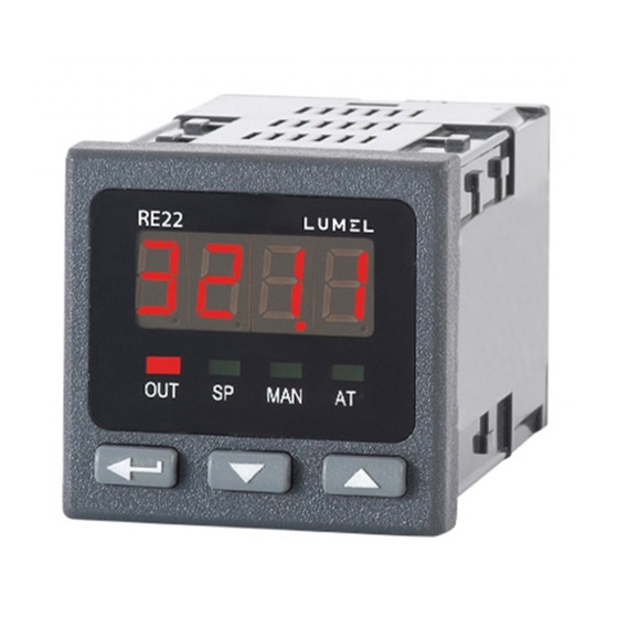
2.2. Electrical Connections See page 16, fig. 3-5. 3. STARTINg TO WORK Controller description Fig.6. View of the controller frontal plate. After connecting to the power, the controller carries out the display test and displays the r e 2 2 inscription, the program version, and next, displays the measured value. - Page 11 4. PROgRAMMINg Of CONTROL PARAMETERS 4.1. Scheme of the controller menu After pressing and holding the push-button during at least 2 sec., it is possible to program parameters. The transition between parameters is carried out by means of push-buttons. The return to the normal working mode follows after the simultaneous pressure of push-buttons, or automatically, after 30 sec from the last push-button pressure.
- Page 12 Fig.9. Menu of controller servicing...
-
Page 13: Technical Data
5. TECHNICAL DATA Input signals and measuring ranges for sensor inputs. Table 1 Sensor type Standard Notation Range Symbol on the display Pt100 Pt100 -199...850°C EN 60751+A2 pt10 Pt1000 Pt1000 -199...850°C EN 60751+A2 Fe-CuNi -100...1200°C EN 60584-1 Cu-CuNi -100...400°C EN 60584-1 NiCr-NiAl -100...1372°C EN 60584-1... - Page 14 - 0...20 mA over 22 mA - 4...20 mA under 1 mA and over 22 mA Control algorithm: P, PD, PI, PID, too-state with hysteresis Range of controller parameter settings: see table 1 (see full version of user’s manual) Kind of outputs: relay: switch over contact, maximal load-carrying capacity: voltage: 250 V a.c., 150 V d.c., current: 5 A 250 V a.c., 5 A 30 V d.c.
-
Page 15: Controller Version Codes
6. CONTROLLER VERSION CODES Table 3 RE22 X X X XX X Input: universal for RTD and TC sensors universal linear: current: 0/4..20 mA, voltage: 0..5/10V as per order Output: relay binary 0/5 V for SSR control as per order... - Page 16 SCHEMATY PODłąCZEŃ ELECTRICAL CONNECTIONS Wykonaæ pod³¹czenia elektryczne do listew zaciskowych a nastêpnie listwy wcisn¹æ do gniazd regulatora. Carry out electrical connections to terminal strips and next, insert strips into controller sockets. sygnały wejściowe/ wyjście/ output input signals zasilanie/ supply Rys.3 Widok listew pod³¹czeniowych regulatora. Fig.3.
- Page 17 wejœcie pr¹dowe wejœcie napiêciowe termoelement 0/4..20 mA 0..5/10 V Current input Thermocouple Voltage input 0/4..20mA 0..5/10V Rys.4. Pod³¹czenie sygna³ów wejœciowych. Fig.4. Connection of input signals. zasilanie / supply zasilanie / Supply wyjœcie - przekaŸnik Output - relay zasilanie / supply wyjœcie - binarne napiêciowe do sterowania SSR Output - binary voltage to control SSR Rys.5.
- Page 18 Zalecenia instalacyjne Regulator RE22 spe³nia wymagania dotycz¹ce odpornoœci na zak³ócenia elektromagnetyczne wystêpuj¹ce w œrodowisku przemys³owym wg obowi¹zuj¹cych norm. W celu uzyskania pe³nej odpornoœci regulatora na zak³ócenia elektro- magnetyczne w œrodowisku o nieznanym poziomie zak³óceñ zaleca siê przestrzeganie nastêpuj¹cych zasad: - nie zasilaæ regulatora z sieci w pobli¿u urz¹dzeñ wytwarzaj¹cych du¿e zak³ócenia impulsowe,...
- Page 19 Installation recommendations The RE22 controller fulfils requirements concerning the fastness against electromagnetic interference occurring in the industrial environment acc. to obligatory standards. In order to obtain a full immunity of the controller against electro- magnetic interference in an unknown environment interference level...
- Page 20 LUMEL S.A. ul. Sulechowska 1, 65-022 Zielona Góra, Poland tel.: +48 68 45 75 100, fax +48 68 45 75 508 www.lumel.com.pl Informacja techniczna: tel.: (68) 45 75 306, 45 75 180, 45 75 260 e-mail: sprzedaz@lumel.com.pl Realizacja zamówień: tel.: (68) 45 75 207, 45 75 209, 45 75 218, 45 75 341 fax.: (68) 32 55 650...
Need help?
Do you have a question about the RE22 and is the answer not in the manual?
Questions and answers