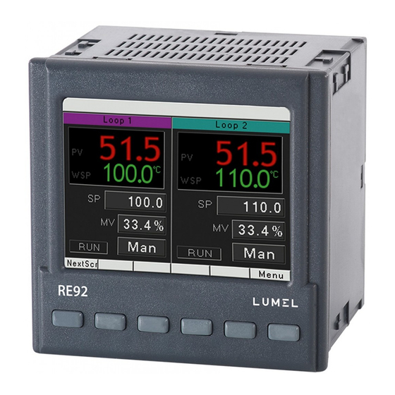
Lumel RE92 User Manual
Dual loop controller 48 x 48 mm
Hide thumbs
Also See for RE92:
- User manual (118 pages) ,
- User manual (67 pages) ,
- User manual (33 pages)
Table of Contents
Advertisement
Quick Links
Advertisement
Table of Contents

Subscribe to Our Youtube Channel
Related Manuals for Lumel RE92


Summary of Contents for Lumel RE92
- Page 1 DUAL LOOP CONTROLLER 96 x 96 mm RE92 USER’S MANUAL...
-
Page 3: Table Of Contents
Contents 1. IntroductIon ..............5 1.1. Purpose ....................5 1.2. Controller properties ................5 2. controller set ..............6 3. basIc requIrements, operatIonal safety ......7 4. InstallatIon ..............7 4.1. Controller installation ................7 4.2. Electrical connections ................9 4.3. - Page 4 9.4. Retransmission outputs ................ 63 9.5. Signal outputs..................64 10. loop confIguratIon ............66 10.1. Controlled signal ................. 66 10.2. Control types ..................66 10.3. Control range ..................72 10.4. Set value in loop ................. 72 10.5. Control algorithms ................72 11.
-
Page 5: Introduction
(e.g. pressure, humidity, flow level). It can control two objects independently or control two physical values in one object (e.g. two-chamber furnaces). 1.2. controller properties rE92 controller is characterized by the following features: • two-loop control and measurement, •... -
Page 6: Controller Set
• modbus master function - querying 2 devices 10 registers each time, • two interface measurement inputs - readout of measured va- lues from external devices via rS-485 Modbus master, • possibility to assign custom names to measurement chan- nels. 2. -
Page 7: Basic Requirements, Operational Safety
3. Basic requirements, operational safety the controller conforms to a safety standard En 61010-1. Additional comments concerning safety: • Assembly and installation of the electrical connections should conducted only by people authorized to perform assembly of electric devices. • Always check the state of connections before turning the controller on. - Page 8 Fig. 1. Controller installation. Dimensions of the controller are presented on the fig. 2. 76,7 Fig. 2. Controller dimensions.
-
Page 9: Electrical Connections
4.2. Electrical connections the controller has three separate strips with screw terminals. two strips with 16 terminals each allow to connect all signal sources by a wire with a 2.5 mm cross-section, and two strips with 10 terminals each allow for connecting by a wire with 1.5 mm cross-section. - Page 10 ConneCting the supply supply supply should be connected to the terminals 51 and 52, according to technical data ConneCtion of 1 And 2 input thermoresistor Pt100 thermoresistor Pt100 in 3-wire system in 2-wire system thermoresistor Pt1000 thermocouples...
- Page 11 voltage input current input 0...5/10 V 0/4...20 mA ConneCtion of input 3 potentiometric current input voltage input input 0/4..20 mA 0...5/10 V ConneCtion of the binAry outputs load OUT6 OUT5 OUT4 OUT3 OUT2 OUT1 output 1–6 – relay...
- Page 12 load OUT2 OUT1 output 1 and 2 – voltage 0/5 V ConneCting the AnAlog outputs output 1A – current 0/4–20 mA load and voltage 0–10 V load OUT1A output 2A – current 0/4–20 mA load and voltage 0–10 V load OUT2A ConneCting the binAry inputs IN1B...
- Page 13 • EIA/tIA 568A for both connectors in strike- -through connection (i.e. between rE92 and hub or switch), • EIA/tIA 568A for the first connector and EIA/ tIA 568B for the second one in the cross-over connection (i.e.
-
Page 14: Recommendations For Installation
(at least 30 cm) and should be crossed only at the right angle (90 degrees). – to connect rE92 controller to the Ethernet it is recommen- ded to use: • u/FtP – twisted pair cable with separate foil shielding for every pair, •... -
Page 15: Starting Work
5. starting work After turning a supply on, the controller displays logo and then moves to the normal operational mode. 6. starting the controller 6.1. Information bar Information bar displays the state of outputs, binary inputs and real-time clock. When active binary outputs and inputs are displayed in black, inactive ones are displayed in light grey color. -
Page 16: Button Markings
6.2. Button markings depending on the service location, controller buttons can perform different functions. Functions are described in the bar on the bottom of the screen. If the button lacks description, it is inactive at the moment. Fig. 5 shows an example of the button marking. -
Page 17: Screen With Programming Control
6.4. Screen with programming control Fig. 7. Screen with programming control 6.5. Screens with the timer function timer reset countdown pause/continuation time bargraph of the countdown time to alarm switching on time to alarm switching off Fig. 8. Alarm Timers screen timer status measured value output holding type... -
Page 18: Change Of Displayed Screens
6.6. changing the display screens Pressing the Screens button, one can switch between the views of the two channels, the first channel and the second. Figure 6 shows the change in display screens for the regulator with the programming control. Button Screens via context Menu... -
Page 19: Edit Mode
via context Menu Fig. 10. Change of the displayed screens - example 6.7. Edit mode Changing the value in the edit field. to change the value in the edit field (i.e. set value), press the Edit button, the first field of the list will by highlighted in yellow. - Page 20 Using the button type field. to use such field (e.g. start/stop control), press the Edit button; the first item in the list will be highlighted in yellow. then use the buttons to select the button type field. Pressing the Exec button per- forms a function appropriate to the given button.
-
Page 21: Context Menu
6.8. context menu Pressing the contxtM button displays the context menu. this menu allows for quick access to a given feature. Fig. 13. Context menu 7. controller configuration 7.1. Menu access password to switch to the controller configuration from the screen display level, choose the Menu button. - Page 22 Button Button Button Button Button Menu...
-
Page 23: Programming Matrix
7.2. Programming matrix menu inputs Analog input 1 Analog input 2 outputs output 1 Analog input 3 output 2 external output 1 output 3 external output 2 output 4 Binary output 1 output 5 Binary output 2 output 6 Binary output 3 Analog output1 modb. -
Page 24: Parameters Description
7.3. Parameters description the list of parameters is presented in the table 1. lista parametrów konfiguracji table 1 parameter modification range parameter factory name setting sensors linear input Inputs Analog input 1 Input type Pt100 Pt100 : thermoresistor Pt100 Pt500 : thermoresistor Pt500 Pt1000: thermoresistor Pt1000 ni100 : thermoresistor ni100 ni1000: thermoresistor ni1000... - Page 25 unit °c c : degrees celsius F : degrees Fahrenheit Pu: physical units %: percent %rH: relative humidity dot.level dP0 : without dP0 : without a decimal a decimal place place dP1 : 1 decimal dP1 : 1 decimal place place dP2 : 2 decimal places...
- Page 26 Analog input 3 4..20mA 0..20mA: linear current 0-20mA Input type 0..10V 4..20mA: linear current 4-20mA r100 0..5V: linear voltage 0-5 V 0..10V: linear voltage 0-10 V r100: potentiometric input 100 ohm r1000: potentiometric input 1000 ohm unit °c °c : degrees celsius °F : degrees Farenheit Pu: physical units %: percent...
- Page 27 unit c : degrees celsius F : degrees Fahrenheit Pu: physical units %: percentage %rH: relative humidity digit Point dP0 : no decimal place dP1 : 1 decimal place dP2 : 2 decimal places Shift -35.00...35.00 Filter off: filter off 0.2: time constant 0.2 s 0.5: time constant 0.5 s 1: time constant 1 s...
- Page 28 PrgEnd: end of the program (response to the rising edge) PrgStop: stop of the program with possible continuation (response to the rising edge) PrgStopBeg: stop the program and jump to the beginning (response to the rising edge) SP-In3: switching to subse- quent SP from the additional input (response to a level)
- Page 29 Binary input 3 as per binary input 1 Modbus binary input 1 as per Binary (Binary input function entered into input 1 register 7590) Modbus binary input 2 as per Binary (Binary input function entered into input 1 register 7592) Modbus binary input 3 as per Binary (Binary input function entered into...
- Page 30 ModbEvIn2 – interface binary input 2 (register 4056) ModbEvIn3 – interface binary input 3 (register 4057) ModbEvIn1neg: inverted interface binary input 1 (register 4055) ModbEvIn2neg: inverted interface binary input 2 (register 4056) ModbEvIn3neg: inverted interface binary input 3 (register 4057) Modbreg: control from interface (register 4058) Modbreg neg: inverted control...
- Page 31 Prg Event none none: none occ.1.Sec: event 1 from a section occ.2.Seg: event 2 from a section occ.3.Sec: event 3 from a section occ.4.Sec: event 4 from a section occ.5.Sec: event 5 from a section occ.6.Sec: event 6 from a section Prg.Block.: deviation block output type none: none...
- Page 32 output 4 Assignment none As per output 1, except for: Modbreg: control from interface (register 4061) Modbreg neg: inverted control from interface (register 4061) Function none Prg. Event none As per output 1 output type cycle time 20.0 output 5 Assignment none As per output 1, except for:...
- Page 33 Analog output 1 Assignment none none: none loop 1: loop 1 loop 2: loop 2 Input 1: input 1 Input 2: input 2 Input 3: input 3 InP1+2+3: input 1 + input 2 + input 3 Modbus In1: interface input 1 Modbus In2: interface input 2 Function none...
- Page 34 loop 1 Inputs Measuring Inp1: input 1 value Inp2: input 2 Inp3: input 3 Inp1+Inp2: input 1 + input 2 Inp1+Inp3: input 1 + input 3 Inp2+Inp3: input 2 + input 3 Modbus In1: interface input 1 Modbus In2: interface input 2 Factor In1 -10.00...10.00 Factor In2...
- Page 35 Setpoint SP type SP1: SP1 set point value SP2: SP2 set point value SP3: SP3 set point value SP4: SP4 set point value In3: set point value from input 3 PrG: set point value from program In1: set point value from input 1 In2: set point value from input 2 Modbus In1: interface input 1 Modbus In2: interface input 2...
- Page 36 -9999...99999 -9999...99999 -9999...99999 -9999...99999 SP lo limit -199.0 -9999...99999 SP Hi limit 999.0 -9999...99999 ramp Mode off: off rate/min: accrual in units / minute rate/h: accrual in units / hour ramp rate -9999...99999 control control type Heat off: control off Heat: heating-type control cool: cooling-type control Heat-cool: heating-cooling control...
- Page 37 Valve close 30 s 3...600 s time Min Work 0.1 s 0.1...99.0 s time out Min 0.00% 0.0...100.0 % out max 100.00% 0.0...100.0 % out Fail -100.0...100.0 ctrl lim lo -9999...99999 ctrl lim Hi 800.0 -9999...99999 PId Parameters PId 1 30.0 °c 0.1...550.0 °c (0.1...990.0 °F)
- Page 38 GS level nb. 2: 2 PId sets used 3: 3 PId sets used 4: 4 PId sets used GS level 1-2 -9999...99999 GS level 2-3 -9999...99999 GS level 3-4 -9999...99999 GS Set PId1 PId1: PId1 set PId2: PId2 set PId3: PId3 set PId4: PId4 set name name...
- Page 39 Programs Program 1 config Prg Start Prg Start PV Start SP Start PV Start SP -9999...99999 time unit mm:ss mm:ss hh:mm ramp unit Hour Holdback disable disable type High Band cycles number 1...9999 Power Fail continue continue Stop End type Stop Stop last SP...
- Page 40 Holdback Val -9999...99999 Event1 Event2 Event3 Event4 Event5 Event6 PId set PId1 PId1 PId2 PId3 PId4 Segment 2 Segment 15 as Segment 1 Program 2 Program 60 as Program 1...
- Page 41 Alarms Alarm 1 type AbsHigh AbsHigh: absolute upper Abslo: absolute lower devHigh: relative upper devlo.: relative lower devInBand: relative internal devoutBand: relative external -9999...99999 deviation -9999...99999 Hysteresis 0.1...99.9 latch off: off on: on overflow off: off state on: on Alarm 2 Alarm 6 as Alarm 1 timers...
- Page 42 type AbsHigh AbsHigh: absolute upper Abslo: absolute lower (active if output –> Assignment: Input 1 or Input 2 or Input 3 or InP1+2+3) 100,0 -9999...99999 (active if output –> Assignment: Input 1 or Input 2 or Input 3 or InP1+2+3) timer 2 timer 6 as timer 1...
- Page 43 Master 1 reg3: register 3 readout. from master 1 Master 1 reg4: register 4 readout. from master 1 Master 1 reg5: register 5 readout. from master 1 Master 1 reg6: register 6 readout. from master 1 Master 1 reg7: register 7 readout. from master 1 Master 1 reg8: register 8 readout.
- Page 44 Interval: archiving at specified time interval AbsHigh: at a interval after ex- ceeding the upper threshold set by SP Abs Abslo.: at a interval after ex- ceeding the lower threshold set by SP Abs Archiv type Interval devHigh: at a interval after ex- ceeding the relative upper threshold devlo.: at a interval after ex- ceeding the relative lower threshold...
- Page 45 Master1 reg3: register 3 readout from master 1 Master1 reg4: register 4 readout from master 1 Master1 reg5: register 5 readout from master 1 Master1 reg6: register 6 readout from master 1 Master1 reg7: register 7 readout from master 1 Master1 reg8: register 8 readout from master 1 Master1 reg9: register 9 readout from...
- Page 46 PV_Input1: measured value from input 1 PV_Input2: measured value from input 2 PV_Input3: measured value from input 3 PV_loop1: measured value in loop 1 SP_loop 1: setpoint value for loop 1 ctrl1_loop1: control signal path 1 from loop 1 ctrl2_loop1: control signal path 2 from loop 1 PV_loop2: measured value in loop 2 SP_loop2: setpoint value for loop 2...
- Page 47 Master2 reg3: register 3 readout from master 2 Master2 reg4: register 4 readout from master 2 Master2 reg5: register 5 readout from master 2 Master2 reg6: register 6 readout from master 2 Master2 reg7: register 7 readout from master 2 Master2 reg8: register 8 readout from master 2 Master2 reg10: register 10 readout...
- Page 48 decimal dot: a integer separator is ‘.’ comma: a integer separator is ‘,’ separator Actions... rip archive Saving all the new records on the Sd card on Sd card (only records that have been recorded since the last download to the Sd card are downloaded) clear archive clear the entire archive...
- Page 49 Mode rtu 8n2 off rtu 8n2 rtu 8E1 rtu 8o1 rtu 8n1 delay 100...5000 ms between polls Master 1 Master 1 off: modbus master off on: modbus master on Address 1...247 Work mode Manual Manual: it must be manually confi- gured: „Base register”, „nr of valu- es”...
- Page 50 ushort 16: unsigned short register (16 bits without character) long 32: long register (32 bits with character) ulong 32: unsigned long register (32 bits without character) float 32: float register (32 bits, variable comma with character) sw float 2x16: swapped float register, value placed in two 16bit registers (byte order 3,2,1,0)
- Page 51 Max nr of req 0...10 Master 2 same as Master 1 Enabled Port 0...65535 Enabled Port 80...32000 Ethernet dHcP off: off on: on Mode Auto Auto: autonegation of baudrate 100M FdX: 100Mbit full duplex 100M HdX: 100Mbit half duplex 10M FdX: 10Mbit full duplex 10M HdX: 10Mbit half duplex IP Address 127.0.0.1 0.0.0.0...255.255.255.255...
- Page 52 user 1 Enabled level level 2 level 0: all parameters change level 1: change of all parameters .other than the Security submenu level 2: change of SP, program number, clock settings Password 0...99999999 user 2 same as user 1 user 3 same as user 1 Settings 100%...
- Page 53 Information type rE92 Boot Version eg. 1.00 Program version 1.00.00 Serial number 12010001 MAc Address 1) – default setting and extent of the changes depends on input 3 field in the ordering code 2) – shown for Ethernet version...
-
Page 54: Inputs And Outputs Of The Controller
8. InPutS And outPutS oF tHE controllEr rE92 controller is fitted with two measuring inputs, one two interface inputs (from slave devices through modbus ma- ster), three binary inputs -hardware, three modbus binary inputs. 8.1. Measuring inputs 1 Input 1 is the source of the measured value used for control and alarms. -
Page 55: Measuring Input 1
be set to 0.2 to 100 seconds. Measuring input 1 parameters can be found in menu: Inputs g Analog input 1. 8.2. Measuring input 2 Input 1 is the source of the measured value used for control and alarms. Measuring input 2 parameters are the same as the ones for input 1 can be found in menu: Inputs g Analog input 2. -
Page 56: Interface Inputs 1,2
8.4. Interface inputs 1, 2 Interface inputs 1 and 2 can be used as: • adjustable signal for any loop, • set value for any loop. • reference signal for controlling the alarms, • source of retransmitted signal to analog output Interface inputs 1 and 2 are inputs for which the measured valu- es are read by the function of modbus master 1 or 2. - Page 57 the controller is also equipped with three additional modbus bi- nary slave inputs - controlled via the interface. Function of interface binary inputs is set through the [Funkcja] parameter, that can be found in menu: Inputs g Modb binary input 1, Inputs gModb binary input 2 i Inputs gModb binary input 3.
-
Page 58: Controller Outputs
If one channel is assigned to more than one binary input, than for each of them must be set a different function. 9. controllEr outPutS rE92 controller has six binary outputs and two analog outputs: current and voltage (optional). 9.1. controlling outputs [Heat] function output is a reverse output. - Page 59 For the proportional control (with the exception of the analog outputs) an impulse period is also set. Impulse period is a time between two subsequent input engagements during proportio- nal control. Impulse period length should be adjusted for the dy- namic properties of the object and characteristics of the output device.
-
Page 60: Alarm Outputs
9.2. Alarm outputs Alarm configuration is done in two steps: 1. In [output k] submenu - where k=1...6 (menu: outputs): • select the number of loop or input allocated to the output being configured – [Assignment] parameter, • set [function] parameter to [Alarm]. 2. -
Page 61: Timer Function
Deviation (>0) Deviation Deviation Deviation (<0) Deviation Deviation relative lower relative internal relative external [DevLo] [DevInBand] [DevOutBand] Fig.15. Alarm types 9.3. timer function timers configuration is done in two steps: 1. In [output k] submenu - where k=1...6 (menu: outputs): select the number of loop or input allocated to the output ■... - Page 62 select the alarm type – parameter [type] – set this para- ■ meter if in the [output -> Assignment] submenu is selec- ted: input 1, input 2, input 3, inp1+2+3, set a set point – parameter [SP] - set this parameter if in ■...
-
Page 63: Retransmission Outputs
timer latch time countdown countdown time[sec] timer alarm Fig. 17. The principle of operation of the timer during a timer latch. 9.4. retransmission outputs Analog output may be used for retransmission of the selected value, e.g. for registering object temperature or copying set values in multi-zone furnaces. -
Page 64: Signal Outputs
Fig. 18. Transformation of the signal to be retransmitted the [retr Min] parameter may be higher than [retr Max], but this will cause the output signal to be inverted. 9.5. Signal outputs Any binary output can be used for „retransmission” of the state of given binary input, the specified bina- ry input interface register, or the register directly con- trolling the binary output. - Page 65 • [EvIn2neg] – binary input 2 release will activate the output, • [EvIn3neg] – binary input 3 release will activate the output. • [ModbEvIn1] – (register 4055) entering value 1 into register activates the output, • [ModbEvIn2] – (register 4056) entering value 1 into register activates the output, •...
-
Page 66: Loop Configuration
10. looP conFIGurAtIon 10.1. controlled signal the signal controlled in a loop might be a measure- ment from the selected source (Inp1, Inp2, Inp3, Modbus In1, Modbus In2) or combination of the measured values from two inputs ( Inp1 + Inp2, Inp1+ Inp3, Inp2 + Inp3). combined control signal is calculated by the controller, using the following formula: controlled signal = [coeff. - Page 67 steering output wyjście sterujące 100% [Rozsunięcie] [dead Band] tor główny tor pomocniczy main loop auxiliary loop (grzanie) (chłodzenie) (cooling) (heat) ° wartość zadana temperatura [ c] temperature [ setpoint Fig. 19. Control with two heating-cooling loops three-step, step-by-step control the controller offers two algorithms of the step-by-step control for cylinder control: •...
- Page 68 Fig.20. Three-step step-by-step control with no feedback the principle of the algorithm shown in Fig. 16 is based on conversion of changing the control signal to the relay opening / closing time referred to the full opening / closing time. the differences between the calculated and the actual valve position are unavoidable because of multiple changes in the di- rection of valve movement due to the inertia of a drive or its wear...
- Page 69 the positioning of the valve will be stopped once the signal is equal to the maximum value. In the specific case, the positioning is performed by completely closing the valve, it is carried out each time after: - turning the controller supply on - changing full open / close time.
- Page 70 First loop should be set to PId control to select the cascade con- trol. In the second loop the parameter [Control type] in menu: loop 2 g control should be set to [Cascade]. For resca- ling the master loop output set the parameters [Casc.so lo] and [Casc.so hi] in menu: loop 2 g Set value.
- Page 71 p i D 4 gs level 3 - 4 g s p o z io m 3 - 4 p i D 3 G S P o z io m 2 - 3 GS Level 2 - 3 P I D 2 GS Level 1 - 2 G S P o z io m 1 - 2 p i D 1...
-
Page 72: Control Range
10.3. control range control range is defined by [Ctrl lim lo] and [Ctrl lim hi] parameters. control range defines limits for the PId control and auto-tuning algorithm. 10.4. Set value in loop A set value in loop may be one of the four values defined SP1, SP2,... - Page 73 wyjście output histereza hysteresis załączone wyłączone wartość measured setpoint wartość value value zadana mierzona Fig. 24. Heating output operation sMArt pid algorithm When high precision of the temperature control is necessary, it is recommended to use PId algorithm. Innovative SMArt PId algorithm ensures increased precision in the extended range of the control object classes.
- Page 74 c) Instability • decrease the proportional band, • decrease the differentiation time, d) Free jump response: • decrease the proportional band, • decrease integration time. Controller operation algorithms Algorytmy działania regulatora trace Przebieg wielkości regulowanej of controlled value Pb td Fig.25.
- Page 75 Auto-tuning the controller has the function to select PId settings. In most cases these settings ensure an optimal control. to begin the auto-tuning, one must select the field St on the screen of a single loop with fixed set-point control and then press a button Exec.
- Page 76 the auto-tuning process will be stopped without coun- ting PId settings, if a supply decay occurs or the field St will be again selected and confirmed. If the auto-tuning is not achieved with success, the er- ror message will be displayed. Auto-tuning and „gain scheduling”...
-
Page 77: Programming Control
11. ProGrAMMInG control 11.1. description of the programming control parameters list of configuration parameters table 3 [Programs] – programs defined for programming control [Program 1] - program 1 submenu [Program 60] - program 60 submenu [Prg.conf.] - podmenu parametrów programu Parameter modification Fac- Symbol... - Page 78 cycles Program 1…999 iteration no. number Power Fail control con- continuation: program after supply tinua- continuation decay tion Stop: control stop End type Program Stop Stop: control stop end control last SP: fixed set-point control with set value from last segment Gain „Gain...
- Page 79 Seg.dura- Segment 00.01 00.01…99.59 tion duration ramp Set value 0.1...550.0 °c 1...5500°c rate ramp rate / time unit time unit (0.1...990.0 °F (1...9900 °F / time unit time unit Holdback upper con- 0.0... 200.0°c 0...2000 °c trol devia- (0.0...360.0 °F) (0...3600 °F tion value;...
-
Page 80: Defining The Set Value Programs
11.2. defining the set value programs up to 60 programs may be defined. one program may include up to 15 sections. to ensure that parameters related to the programming control are displayed in the menu, a [sp Mode] parameter must be set to [PRG]. - Page 81 800°C 50°C czas time OUT2 czas 40 min 120 min 100 min time Fig.26. Example program Parameter value for the example program table 5 Parameter Value Meaning Set value accrual start PrgStart Start PV from the initial (current) temperature the unit of time: hours time unit hh:mm and minutes...
- Page 82 Seg.type Accrual Segment type: ramp rate target SP target set value: 800.0 °c ramp rate 20.0 °c / Seg- ramp rate minute ment 1 Holdback Block active when deviation is higher than 50.0 °c Event 1 Events 1 on output 2: off Segment Segment Section type: segment...
-
Page 83: Modbus
12. ArcHIVInG 12.1. Introduction the controllers with the Ethernet interface are equipped with an internal memory for storing archived data. Archiving is divided into three independent groups. the internal memory allows you to register up to 1.2 million records in each group. the memory is a ring buffer type one. -
Page 84: Copying Archive To Sd Card
12.3. copying archive to Sd card Because the size of a single file on the Sd card is limited to approx. 10 MB, after the internal memory is full with the number of the records (approx. 35 thous.), which correspond to a file size approx. -
Page 85: Archive File Structure
the controller creates the directories and the files on the memory card while the archive is being copied. An example of the directory structure is shown in Fig. 27. Fig.27. An example of the directory structure on the SD card data on the Sd card are stored in the files in the directories (the serial number of the controller), then (year, month of archive copy) –... - Page 86 the fields in the line describing the record have the following meanings: • date – date of data recording, date separator is the cha- racter „-” • time – hour, minute, second of recorded data, a separator is the character „:” •...
- Page 87 PV_In3 - measuring value at input 3 PV_cH1 - measuring value in loop 1 SP_cH1 - set point in loop 1 Y1_cH1 - loop 1 control signal in loop 1 Y2_cH1 - loop 2 control signal in loop 1 PV_cH2 - measuring value in loop 2 SP_cH2 - Set point in loop 2 Y1_cH2 - loop 1 control signal in loop 2 Y2_cH2 - loop 2 control signal in loop 2...
-
Page 88: Copying Archive To Sd Card
12.5. Status bar of the archiving registration status bar indicates the current state of the archiving as well as the status of the Sd card inserted in the con- troller. Icon Icon color comments current state of the archiving 1 – 1 archiving group black –... -
Page 89: Downloading Archive Files
the percentage fill Sd card green background Value in the range 0…70% orange background 70% of Sd card spa- ce is full. It is recommended to delete unnecessary files. red background It is less than 70 MB of free space on the Sd card left. -
Page 90: Modbus
13. ModBuS Protocol 13.1. Introduction rE92 controller is equipped with two rS-485 serial interfaces, one Slave, the second Master or optionaly with Ethernt interface with implemented ModBuS Slave protocol. 13.2. Modbus master rS-485 master interface of the controller (connectors 13-12-11) operates in Master mode and can query one or two slave devices connected to it. - Page 91 template If you select a template, select the de- vice to be queried from the list Base register Base register number number of registers number of queried registers register type type of queried registers Interval time of query [ms] Max. response time Maximum response time [ms] Master response fun- Function selection for Master mode...
-
Page 92: Modbus Slave
13.3. Modbus Slave Summary of the rE92 controller Modbus protocol: – device address: 1..247, – baud rate: 4800, 9600, 19200, 38400, 57600 bit/s, 115200 bit/s – operation modes: rtu, – mode: 8n2, 8E1, 8o1, 8n1, – maximum response time: 500 ms, –... -
Page 93: Error Codes
13.3.1. Error codes If the controller receives query with the transmis- sion error or checksum error, then such query will be ignored. When a query with correct syntax and invalid values is found, the controller returns an error code. table 7 shows error codes and their meaning. Error codes table 7 code... - Page 94 Map of the registers from address 4000 table 9 Parameter Description range 4000 1…11 command register 1 – switch to manual operation in loop 1 2 – switch to manual operation in loop 2 3 – switch from manual operation to automatic control in loop 1 4 –...
- Page 95 4003 controller manufacture code bit 1 0 – InPut 3: 0 0 – input 3 – none 1 0 – output 3 – current 0/4–20 mA 1 1 – output 3 – voltage 0–10 V bit 3 2 – outPut 1 and 2: 0 1 –...
- Page 96 4016 0…0x7FFF Status of timer 4...6 (see tab.14) 4017 0…1 Switching off/on the timer 1 0 – timer off 1 – timer on 4018 0…1 Switching off/on the timer 2 0 – timer off 1 – timer on 4019 0…1 Switching off/on the timer 3 0 –...
- Page 97 4029 0…1 Alarm type of timer 1 0 – absolute upper 1 – absolute lower 4030 0…1 Alarm type of timer 2 0 – absolute upper 1 – absolute lower 4031 0…1 Alarm type of timer 3 0 – absolute upper 1 –...
- Page 98 4041 0…1 Enabling only archiving in the archiving group 3 0 – disabling archiving 1 – enabling archiving 4042 0…6 Archiving type in the archiving group 1 0 – Interval: archiving at a de- fined time interval 1 - Absolute upper: archiving at the interval after exceeding the upper threshold set by ab- solute SP...
- Page 99 4045 0…32 the parameter triggering the threshold archiving in archi- ving group 1 0 – PV_Inp1: measuring value at input 1 1 – PV_Inp2: measuring value at input 2 2 – PV_Inp3: measuring value at input 3 3 – PV_loop 1: measuring va- lue in loop 1 4 –...
- Page 100 21 – Master1 reg9: value 9 from modbus master 1 22 – Master1 reg10: value 10 from modbus master 1 23 – Master2 reg1: value 1 from modbus master 2 24 – Master2 reg2: value 2 from modbus master 2 25 –...
- Page 101 3 – PV_ loop1: measuring va- lue in loop 1 4 – SP_ loop1: set point for loop 1 5 –ctrl1_loop1: control loop 1 control signal at loop 1 6 – ctrl2_loop1: control loop 2 control signal at loop 1 7 –...
- Page 102 28 – Master2 reg6: value 6 from modbus master 2 29 – Master2 reg7: value 7 from modbus master 2 30 – Master2 reg8: value 8 from modbus master 2 31 – Master2 reg9: value 9 from modbus master 2 32 –...
- Page 103 4058 0…1 Interface binary input 2 0 - inactive input 1 - active input 4059 0…1 Interface binary input 3 0 - inactive input 1 - active input 4060 0…1 control of binary output 1 0 - inactive output 1 - active output 4061 0…1 control of binary output 2...
- Page 104 4072 0...65535 character 3 and 4 of loop 2 proper name 4073 0...65535 character 5 and 6 of loop 2 proper name 4074 0...65535 character 7 and 8 of loop 2 proper name 4075 0...65535 character 9 and 10 of loop 2 proper name register 4004 –...
- Page 105 register 4005 – alarm state table 11 description State of the alarm 1.:1 – active, 0 – inactive Status of the alarm 2.:1 – active, 0 – inactive Status of the alarm 3.:1 – active, 0 – inactive Status of the alarm 4.:1 – active, 0 – inactive Status of the alarm 5.:1 –...
- Page 106 register 4006 – error register table 12 description uncalibrated input 1 uncalibrated input 2 uncalibrated input 3 uncalibrated input 1 (current) uncalibrated input 1 (voltage) uncalibrated input 2 (current) uncalibrated input 2 (voltage) 6-14 reserved controller memory checksum error...
- Page 107 register 4015 – status of the timers 1..3 table 13 description 4...0 timer 1 x00000 – other statuses x00001 – timer enabled waiting for event x00010 – countdown x00100 – timer pause x01000 – end of the countdown x10000 – alarm timer on (output actuated) 9…5 timer 2 x00000 –...
- Page 108 9…5 timer 5 x00000 – other statuses x00001 – timer enabled waiting for event x00010 – countdown x00100 – timer pause x01000 – end of the countdown x10000 – alarm timer on (output actuated) 14…10 timer 6 x00000 – other statuses x00001 –...
- Page 109 7058 time to switch on the alarm timer 1 7060 time to switch on the alarm timer 2 7062 time to switch on the alarm timer 3 7064 time to switch on the alarm timer 4 7066 time to switch on the alarm timer 5 7068 time to switch on the alarm timer 6 7070...
- Page 110 5004 0...4 unit of interface input 1 c : degree celsius F : degrees Fahrenheit 2 - Pu: physical units 3 - %: percentage 4 - %rH: relative humidity, 5006 0...2 Position of decimal place of interface input 1 0 - dP0 : without decimal place 1 - dP1 : 1 decimal place 2 - dP2 : 2 decimal places 5008...
- Page 111 5016 0...4 unit of interface input 2 c : degree celsius F : degrees Fahrenheit 2 - Pu: physical units 3 - %: percentage 4 - %rH: relative humidity, 5018 0...2 Position of decimal place of interface input 2 0 - dP0 : without decimal place 1 - dP1 : 1 decimal place 2 - dP2 : 2 decimal places 5020...
- Page 112 5036 0... list of modbus master parameters 0x00080000 selected for archiving in archiving group 1 0x00000001 - M1_V1 : value 1 from modbus master 1 0x00000002 - M1_V2 : value 2 from modbus master 1 0x00000004 - M1_V3 : value 3 from modbus master 1 0x00000008 - M1_V4 : value 4 from modbus master 1...
- Page 113 0x00020000 - M2_V8 : value 8 from modbus master 2 0x00040000 - M2_V9 : value 9 from modbus master 2 0x00080000 - M2_V10 : value 10 from modbus master 2 5038 0... list of modbus master parameters selected for archiving in archiving 0x00080000 group 2 (as per register 5036) 5040...
- Page 114 5054 0...65535 Base register of modbus master 1 5056 1...10 number of registers of modbus master 1 5058 0...12 register type of modbus master 1 0 - char 8: char register (8 bits with character) 1 - uchar 8: unsigned char register (8 bits without character) 2 - short 16: short register (16 bits with character)
- Page 115 11 - ulong 2x16: unsigned long register, value set in two 16-bit registers (32 bits without character, byte order 1,0,3,2) 12 - sw ulong 2x16 : swapped unsigned long register, value set in two 16-bit registers (32 bits without character, byte order 3,2,1,) 5060 0...1...
- Page 116 5068 0...10 Maximum number of modbus master 1 repetitions Maximum number of repeated queries in absence of response from device 5070 0...1 Modbus Master 2 0 - off 1 - on 5072 1...247 Address of modbus master 2 5074 0...1 operating mode of modbus master 2 0 - Manual (to be configured manu- ally: “Base register”, „Value numer”...
- Page 117 7- sw float 2x16: swapped float register, value set in two 16-bit registers (byte order 3,2,1,0) 8- float 2x16: float register, value set in two 16-bit registers (byte order 1,0,3,2) 9- long 2x16: long register, value set in two 16-bit registers (32 bits with character, byte order 1,0,3,2) 10- sw long 2x16: swapped long...
- Page 118 1 - p30u dISP VAl1 - register 7505 - displayed value, MEAS VAl - register 7510 - measured value, dISP VAl2 - register 7512 - second displayed value 5084 5...36000 Query interval of modbus master 2 [ms] 5086 100...5000 Maximum response time to query frame of modbus master 2 [ms] 5088...
- Page 119 5212 Value 7 read by modbus master 1 5214 Value 8 read by modbus master 1 5216 Value 9 read by modbus master 1 5218 Value 10 read by modbus master 1 5220 Value 1 read by modbus master 2 5222 Value 2 read by modbus master 2 5224...
- Page 120 7012 loop 2 controlling signal in loop 1 7014 Measuring value in loop 2 7016 Set point value in loop 2 7018 loop 1 controlling signal in loop 2 7020 loop 2 controlling signal in loop 2 7058 time to switch on the alarm timer 1 7060 time to switch on the alarm timer 2 7062...
- Page 121 Map of the registers from address 7100 table 19 Parameter Description range 7100 0…18 type of input no. 1: 0 – thermoresistor Pt100 1 – thermoresistor Pt500 2 – thermoresistor Pt1000 3 – thermoresistor ni100 4 – thermoresistor ni1000 5 – thermoresistor cu100 6 –...
- Page 122 7108 0…50.0 cold terminals temperature with manual compensation for input 1 7110 -9999…99999 Indication for the lower limit for input 1 (linear input) 7112 -9999…99999 Indication for the upper limit for input 1 (linear input) 7114 -35.00…35.00 Measured value shift for input 1 7116 0…9 digital filter of input no 1:...
- Page 123 7120 0…2 unit of input no 2: 0 – degrees celsius 1 – degrees Fahrenheit 2 – physical units 7122 3) 4) decimal point position for input 2: 0…1 0 – without a decimal place 0…2 1 – 1 decimal place 2 –...
- Page 124 7138 0…2 unit of input no 3: 0 – degrees celsius 1 – degrees Fahrenheit 2 – physical units 7140 decimal point position for input 3: 3) 4) 0…1 0 – without a decimal place 0…2 1 – 1 decimal place 2 –...
- Page 125 10 – switching to subsequent SP from the additional input - In3 11 – alarm reset of timer 1 12 – alarm reset of timer 2 13 – alarm reset of timer 3 14 – alarm reset of timer 4 15 –...
- Page 126 19 – switches to SP from first interface input 20 – switches to SP from second inter- face input 21 - switches to subsequent SP: SP1>>SP2>>SP3>>SP4>> SPIn1>>SPIn2>>SPIn3>> SPMd1>> SPMd2>>SP1 7154 0…21 Function of binary input 3: 0 – none 1 – stop automatic control 2 –...
- Page 127 7156 0…22 Allocation of output 1: 0 – none 1 – loop 1 2 – loop 2 3 – input 1 4 – input 2 5 – input 3 6 – input 1 + input 2 + input 3 7 – binary input 1 8 –...
- Page 128 7160 0…7 output 1 program event: 0 – none 1 – event 1 from a segment 2 – event 2 from a segment 3 – event 3 from a segment 4 – event 4 from a segment 5 – event 5 from a segment 6 –...
- Page 129 7166 0…7 output 2 function: 0 – none 1 – heating 2 – cooling 3 – opening a valve 4 – closing a valve 5 – alarm 2 6 – programming control event 7 – slave loop signal by cascade control 8 –...
- Page 130 19 – inverted interface binary input 2 (register 4056) 20 – inverted interface binary input 3 (register 4057) 21 – control of output 2 through interface (register 4060) 22 – inverted control of output 2 through interface (register 4060) 7174 0…7 output 3 function: 0 –...
- Page 131 13 – interface input 1 14 – interface input 2 15 – interface binary input 1 (register 4055) 16 – interface binary input 2 (register 4056) 17 – interface binary input 3 (register 4057) 18 – inverted interface binary input 1 (register 4055) 19 –...
- Page 132 7188 0…12 Allocation of input 5: 0 – none 1 – loop 1 2 – loop 2 3 – input 1 4 – input 2 5 – input 3 6 – input 1 + input 2 + input 3 7 – binary input 1 8 –...
- Page 133 7192 0…7 output 5 program event: 0 – none 1 – event 1 from a segment 2 – event 2 from a segment 3 – event 3 from a segment 4 – event 4 from a segment 5 – event 5 from a segment 6 –...
- Page 134 7198 0…7 output 6 function: 0 – none 1 – heating 2 – cooling 3 – opening a valve 4 – closing a valve 5 – alarm 6 6 – programming control event 7 – slave loop signal by cascade control 8 –...
- Page 135 7210 -9999… Min for retr. of analog output 1 99999 7212 -9999… Max for retr. of analog output 1 99999 7214 0…2 I-output type for analog output 1: 0 – none 1 – 4…20 mA 2 – 0…20 mA 7216 0…2 u-output type for analog output 1: 0 –...
- Page 136 7228 0…2 I-output type for analog output 2: 0 – none 1 – 4…20 mA 2 – 0…20 mA 7230 0…2 u-output type for analog output 2: 0 – none 1 – 0…5 V 2 – 0…10 V 7232 0…7 Measuring value in loop 1: 0 –...
- Page 137 7242 0…9 SP type in loop 1: 0 – SP1 set point value 1 – SP2 set point value 2 – SP3 set point value 3 – SP4 set point value 4 – set point value from input 3 5 – set point value from program 6 –...
- Page 138 7248 -9999...99999 SP2 set value in loop 1 7250 -9999...99999 SP3 set value in loop 1 7252 -9999...99999 SP4 set value in loop 1 7254 -9999...99999 SP setting lower limit in loop 1 7256 -9999...99999 SP setting upper limit in loop 1 7258 0…2 Set value accrual in loop 1:...
- Page 139 7282 0.0...100.0 control signal correction for P or Pd of PId1 set in loop 1 7284 0...550.0 [ PId2 set proportional band in loop 1 0...990.0 [ 7286 0...9999 Integration time constant [s] from PId2 set in the loop 1 7288 0.0...2500.0 differentiation time constant [s] from...
- Page 140 7314 0...2 „Gain Scheduling” function in loop 1: 0 – off 1 – switched according to set value 2 – selected fixed PId set 7316 0...2 number of PId sets for Gain Schedu- ling, switched according to the value set in loop 1: 0 –...
- Page 141 7334 0…14 Binary inputs in loop 2: 0 – none 1 – binary input 1 2 – binary input 2 3 – binary input 3 4 – binary input 1 and 2 5 – binary input 1 and 3 6 – binary input 2 and 3 7 –...
- Page 142 45 – program numer 46 46 – program numer 47 47 – program numer 48 48 – program numer 49 49 – program numer 50 50 – program numer 51 51 – program numer 52 52 – program numer 53 53 –...
- Page 143 7360 0.1...100.0 Hysteresis in loop 2 7362 -99.9...99.9 distance range in loop 2 7364 -100.0...100.0 control signal in loop 2 7366 -9999...99999 control lower limit in loop 2 7368 -9999...99999 control upper limit in loop 2 7370 0...550.0 [ PId1 set proportional band in loop 2 0...990.0 [ 7372 0...9999...
- Page 144 7396 0...9999 Integration time constant [s] from PId4 set in the loop 2 7398 0.0...2500.0 differentiation time constant [s] from PId4 set in the loop 2 7400 0.0...100.0 control signal correction for P or Pd of PId4 set in loop 2 7402 0.1...200.0 Proportional band of cooling loop...
- Page 145 7420 0...5 Alarm type 1: 0 – absolute upper 1 – absolute lower 2 – relative upper 3 – relative lower 4 – relative internal 5 – relative internal 7422 -9999...99999 Alarm 1 set value 7424 -9999...99999 Alarm 1 deviation (for relative alarms) 7426 0.1...99.9 Alarm 1 hysteresis...
- Page 146 7444 -9999...99999 Alarm 3 deviation (for relative alarms) 7446 0.1...99.9 Alarm 3 hysteresis 7448 0...1 Memory of the alarm 3: 0 – off 1 – on 7450 0...5 Alarm type 4: 0 – absolute upper 1 – absolute lower 2 – relative upper 3 –...
- Page 147 7470 0...5 Alarm type 6: 0 – absolute upper 1 – absolute lower 2 – relative upper 3 – relative lower 4 – relative internal 5 – relative internal 7472 -9999...99999 Alarm 6 set point value 7474 -9999...99999 Alarm 6 deviation (for relative alarms) 7476 0.1...99.9 Alarm 6 hysteresis...
- Page 148 7492 0...1 Show binary inputs state 0 – no 1 – yes 7494 0...1 Show clock 0 – no 1 – yes 7496 0.0...100.0 Minimum control signal in loop 1 7498 0.0...100.0 Maximum control signal in loop 1 7500 0.0...100.0 Minimum control signal in loop 2 7502 0.0...100.0...
- Page 149 7534 -9999...99999 Set point value for alarm timer 2 7536 -9999...99999 Set point value for alarm timer 3 7538 -9999...99999 Set point value for alarm timer 4 7540 -9999...99999 Set point value for alarm timer 5 7542 -9999...99999 Set point value for alarm timer 6 7544 0…1 Alarm 1 status if the measuring range is...
- Page 150 7562 5...86400 Archiving interval for group 2 archiving 7564 5...86400 Archiving interval for group 3 archiving 7566 0... the list of parameters selected for archiving 0x00001FFF in the archiving group 1: 0x00000001 - PV_Input1: measuring value at input 1 0x00000002 - PV_Input2: measuring value at input 2 0x00000004 - PV_Input3: measuring value at input 3...
- Page 151 7574 -9999...99999 Set point for achriving group 2 at archi- ving type: AbsHigh, Abslo 7576 -9999...99999 Set point for achriving group 3 at archi- ving type: AbsHigh, Abslo 7578 -9999...99999 deviation for archiving group 1 at relative archiving type 7580 -9999...99999 deviation for archiving group 2 at relative archiving type 7582...
- Page 152 18 – switching to SP from the input 2 19 – switching to SP from the first inter- face input 20 – switching to SP from the second interface input 21 - switching to subsequent SP: SP1>> SP2>>SP3>>SP4>>SPIn1>>SPIn2>>S PIn3>>SPMd1>> SPMd2>>SP1 7592 0…21 Function of interface binary input 2:...
- Page 153 7594 0…21 Function of interface binary input 3: 0 – none 1 – stop automatic control 2 – switch to manual operation 3 – switches to subsequent SP SP1<->SP2, SP2<->SP3, SP3<->SP4, SP4<->SP1 4 – program start 5 – jump to the next segment 6 –...
- Page 154 Map of the registers from address 7600 table 20 Parameter Description range 7600 0…29 number of realized program (30 means thirty-first program) – loop 2 7602 0…1 Program start/stop – loop 1 0 – program stop 1 – program start (saving causes program to start from the beginning) 7604 0…1...
- Page 155 7616 Program time elapsed [s] - loop 1 7618 Program time remaining [s] – loop 1 7620 reserved 7622 reserved 7624 reserved 7626 reserved 7628 reserved 7630 30…59 number of realized program (30 means program) – loop 2 7632 0…1 Program start/stop –...
- Page 156 7642 Section time elapsed [s] - loop 2 7644 Segment time remaining [s] – loop 2 7646 Program time elapsed [s] - loop 2 7648 Program time remaining [s] – loop 2 7650 reserved 7652 reserved 7654 reserved 7656 reserved 7658 reserved...
- Page 157 Map of the registers from address 7660 table 20 Address Last register first Description address register 7660 7676 Program 1 parameters 7678 7886 Sections 1 – 15 of program 1 7888 7904 Program 2 parameters 7906 8114 Sections 1 – 15 of program 2 8116 8132 Program 3 parameters...
- Page 158 9958 10166 Sections 1 – 15 of program 11 10168 10184 Program 12 parameters 10186 10394 Sections 1 – 15 of program 12 10396 10412 Program 13 parameters 10414 10622 Sections 1 – 15 of program 13 10624 10640 Program 14 parameters 10642 10850 Sections 1 –...
- Page 159 12904 12920 Program 24 parameters 12922 13130 Sections 1-15 of program 24 13132 13148 Program 25 parameters 13150 13358 Sections 1-15 of program 25 13360 13376 Program 26 parameters 13378 13568 Sections 1-15 of program 26 13588 13604 Program 27 parameters 13606 13814 Sections 1-15 of program 27...
- Page 160 15658 15866 Sections 1-15 of program 36 15868 15884 Program 37 parameters 15886 16094 Sections 1-15 of program 37 16096 16112 Program 38 parameters 16114 16322 Sections 1-15 of program 38 16324 16340 Program 39 parameters 16342 16550 Sections 1-15 of program 39 16552 16568 Program 40 parameters...
- Page 161 18604 18620 Program 49 parameters 18622 18830 Sections 1-15 of program 49 18832 18848 Program 50 parameters 18850 19058 Sections 1-15 of program 50 19060 19076 Program 51 parameters 19078 19286 Sections 1-15 of program 51 19288 19304 Program 52 parameters 19306 19514 Sections 1-15 of program 52...
- Page 162 register map for single program table 22 Parameter Marking description range PrgStart 0…1 Program start method 0 – from the value defined by SP0 1 – from the current measured value Start SP MIn..MAX Initial set point value time unit 0…1 unit of the segment duration time...
- Page 163 + 12 Power 0…1 control after supply Fail decay 0 – program continu- ation 1 – control stop + 14 End type 0…1 Program end control 0 – control stop 1 – fixed set-point con- trol with set value from last segment + 16 Gain...
- Page 164 + 10 Events 0…7 Events state (bit sum) bit 0 set – event 1 bit 1 set – event 2 bit 2 set – event 3 bit 3 set – event 4 bit 4 set – event 5 bit 5 set – event 6 + 12 0…3 PId set for a segment...
- Page 165 + 42 Seg.type + 44 target SP + 46 Segment time + 48 ramp as per segment 1 rate + 50 Holdback + 52 Events + 54 + 56 Seg.type + 58 target SP + 60 Segment time as per segment 1 + 62 ramp rate...
- Page 166 + 70 Seg.type + 72 target SP + 74 Segment time as per segment 1 + 76 ramp rate + 78 Holdback + 80 Events + 82 + 84 Seg.type + 86 target SP + 88 Segment time + 90 ramp as per segment 1 rate...
- Page 167 + 98 Seg.type + 100 target SP + 102 Segment time + 104 ramp as per segment 1 rate + 106 Holdback + 108 Events + 110 + 112 Seg.type + 114 target SP + 116 Segment time + 118 ramp as per segment 1 rate...
- Page 168 + 140 Seg.type + 142 target SP + 144 Segment time + 146 ramp as per segment 1 rate + 148 Holdback + 150 Events + 152 + 154 Seg.type + 156 target SP + 158 Segment time as per segment 1 + 160 ramp rate...
- Page 169 + 182 Seg.type + 184 target SP + 186 Segment time + 188 ramp as per segment 1 rate + 190 Holdback + 192 Events + 194 + 196 Seg.type + 198 target SP + 200 Segment time + 202 ramp as per segment 1 rate...
-
Page 170: Ftp Server
14. FtP SErVEr the controllers with Ethernet interface have built-in FtP file exchange protocol. the controller works as a server, allowing the clients to access the file system on the Sd card inserted in the controller. Access to the files is possible using a computer, a tablet with installed FtP client or other device ac- ting as a FtP client. - Page 171 the program FileZilla could be an example of the FtP client (Fig. 29). You can view and download the archive files by entering the IP address of the controller in the address field. Fig. 29. View of the FTP session in the program FileZilla...
-
Page 172: Web Server
WEB SErVEr Access to the Web server is achieved by entering the meter IP address in the web browser, e.g .: http://192.168.1.030 (where 192.168.1.030 is the set address of the meter). the stan- dard port for web server is port „80”. Server port may be chan- ged by the user. -
Page 173: Software Upgrade
SoFtWArE uPGrAdE controller software may be upgraded. new software versions are available as a one file on the website: www.lumel.com.pl. the correct file name is „rE92.img”. If it is different, please change it to the correct name. After copying this file... - Page 174 chromel – kopel (l) gost r -100...800 °C -148...1472 °F 0.3% 8.585-2001 linear current (i) 0...20 mA 0...20 mA 0.2% ± 1 digit linear current (i) 4...20 mA 4...20 mA 0.2% ± 1 digit linear voltage (U) 0...5 V 0...5 V 0.2% ±...
- Page 175 input 3 (depends on input 3 in ordering code) Sensor type Range intrinsic error linear current 0...20 mA 0.2% ± 1 digit linear current 4...20 mA 0.2% ± 1 digit linear voltage 0...5 V 0.2% ± 1 digit linear voltage 0...10 V 0.2% ±...
- Page 176 Analog output types 1A and 2A: – 1 k analog voltage 0…10 V atr load – analog current 0…20 mA, 4…20 mA 500 at r load Way of output operation: – reverse for heating – direct for cooling Analog outputs error 0.5% of the range digital interface...
- Page 177 – resistance of wires connecting the resistance thermometer or < 20 / wire thermocouple with controller power input < 16 VA Weight < 0.5 kg protection grade ensured by the housing acc. to En 60529 – from the frontal plate IP65 –...
-
Page 178: Controller Ordering Code
18. controller orDering coDe Versions and ordering Table 19 RE92 - X X X X X Input 3: none current: 0/4...20 mA voltage: 0...5/10 V potentiometric transmitter: 100/ 1000 Ω 3 Output 1 and 2: 2 relays 2 binary outputs 0/5 V... - Page 179 Modbus Slave – supply 85...253 V a.c./d.c example of order: the code re92 -1-1-0-1-0-00-e-0 means: rE92 - rE92 controller, 1 - with additional input: current 0/4...20 mA, 1 - output 1 and 2: 2 relays, 0 - analog outputs: none,...
- Page 180 LUMEL S.A. ul. Sulechowska, 65-022 Zielona Góra, POLAND tel.: +48 68 45 75 100 www.lumel.com.pl Export department: tel.: (+48 68) 45 75 139, 45 75 233, 45 75 321, 45 75 386 fax.: (+48 68) 32 54 091 e-mail: export@lumel.com.pl...
Need help?
Do you have a question about the RE92 and is the answer not in the manual?
Questions and answers