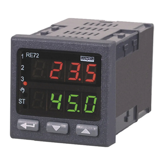
Lumel RE72 User Manual
48x48mm
Hide thumbs
Also See for RE72:
- User manual (96 pages) ,
- User manual & quick start (33 pages) ,
- Quick start manual (33 pages)

Subscribe to Our Youtube Channel
Related Manuals for Lumel RE72


Summary of Contents for Lumel RE72
- Page 1 CONTROLLER 48x48mm RE72 TYPE Automatización Industrial USER’S MANUAL Telf.: 423-5567 / 711-9345 - RPM.: #981156320 / *975084 / #999976999 E-mail.: ventas.1@csrimport.com / www.csrimport.com Automatización Industrial...
-
Page 2: Table Of Contents
RE72-09B User’s Manual CONTENTS: APPLICATION ....................... 3 CONTROLLER SET ...................... 3 BASIC REQUIREMENTS, OPERATIONAL SAFETY ............ 4 INSTALLATION ......................4 4.1. Controller Installation ..................... 4 4.2. Electrical Connections ....................5 4.3. Installation Recommendations ..................7 STARTING TO WORK ....................7 SERVICE ........................ -
Page 3: Application
User’s Manual 1. APPLICATION The RE72 controller is destined for the temperature control in plastics, food, dehydration industries and everywhere when the temperature change stabilization is necessary. The measuring input is universal for resistance thermometers (RTD), thermocouple sensors (TC), or for linear standard signals. -
Page 4: Basic Requirements, Operational Safety
RE72-09B User’s Manual 3. BASIC REQUIREMENTS, OPERATIONAL SAFETY In the safety service scope, the controller meets to requirements of the EN 61010-1 standard. Observations Concerning the Operational Safety ▪ All operations concerning transport, installation, and commissioning as well as maintenance, must be carried out by qualified, skilled personnel, and national regulations for the prevention of accidents must be observed. -
Page 5: Electrical Connections
RE72-09B User’s Manual max. 93 max.15 Fig. 2. Controller dimensions. 4.2. Electrical Connections The controller has two separable terminal strips with screw terminals. One strip enables to connect the supply and outputs by a wire of 2.5 mm cross-section. The second strip enables to connect input signals by a wire of 1.5 mm... - Page 6 RE72-09B User’s Manual Pt100 Pt100 Pt1000 zwora zwora jumper jumper RTD Pt100 in two-wire RTD Pt100 in 3-wire RTD Pt1000 system system 0/4...20 mA 0...5/10 V jumper zwora Thermocouple Current input 0/4..20mA Voltage input 0..5/10V Fig. 5. Input signals 0/4...20 mA Fig.
-
Page 7: Installation Recommendations
RE72-09B User’s Manual Fig. 9. Current transformer input B (-) RS-485 A (+) Fig. 10. RS-485 Interface Fig. 11. Supply of 24V transducers 4.3. Installation Recommendations In order to obtain a full fastness against electromagnetic noise, it is recommended to observe following... -
Page 8: Re72-09B User's Manual
RE72-09B User’s Manual Measured value Signaling the change Set point value Change acceptation To change the set point value Press one of the push-button Fig. 12. Fast change of set point value Automatización Industrial Telf.: 423-5567 / 711-9345 - RPM.: #981156320 / *975084 / #999976999 E-mail.: ventas.1@csrimport.com / www.csrimport.com... -
Page 9: Service
RE72-09B User’s Manual 6. SERVICE The controller service is presented on the fig. 13 Automatización Industrial Fig. 13. Menu of controller service Telf.: 423-5567 / 711-9345 - RPM.: #981156320 / *975084 / #999976999 E-mail.: ventas.1@csrimport.com / www.csrimport.com Automatización Industrial... -
Page 10: Programming Controller Parameters
RE72-09B User’s Manual 6.1. Programming Controller Parameters The pressure and holding down the @ push-button during ca 2 sec. causes the entry in the programming matrix. The programming matrix can be protected by an access code. In case when giving a wrong value of the code, it is only possible to see settings through – without the possibility of changes. -
Page 11: Programming Matrix
RE72-09B User’s Manual 6.2. Programming Matrix Automatización Industrial Fig. 14. Programming matrix Telf.: 423-5567 / 711-9345 - RPM.: #981156320 / *975084 / #999976999 E-mail.: ventas.1@csrimport.com / www.csrimport.com Automatización Industrial... -
Page 12: Setting Change
RE72-09B User’s Manual 6.3. Setting Change The change of the parameter setting begins after pressing the @ push-button during the display of the parameter name. The setting selection is carried out through ? and > push-buttons, and accepted by the @ push-button. - Page 13 RE72-09B User’s Manual Range of parameter Manufacturer Parameter symbol changes Parameter description setting sensors Linear input Indication for the lower iNlo threshold of the linear main -1999…9999 input Indication for the upper iNHi threshold of the linear main -1999…9999 100.0 input -100.0…100.0 °...
- Page 14 RE72-09B User’s Manual Range of parameter Manufacturer Parameter symbol changes Parameter description setting sensors Linear input AHi: upper absolute alarm Al o: lower absolute alarm dwH i: upper relative alarm dwl o: lower relative alarm dwi n: inner relative alarm...
- Page 15 RE72-09B User’s Manual Range of parameter Manufacturer Parameter symbol changes Parameter description setting sensors Linear input Y0p: control signal of stepper control – opening YCl: control signal of stepper control – closing Coo l control signal - cooling AH i: absolute upper alarm...
- Page 16 RE72-09B User’s Manual Range of parameter Manufacturer Parameter symbol changes Parameter description setting sensors Linear input p i d 1 : PID1 set p i d 2: PID2 set Gset Selection of the constant PID p i d 1 p i d 3: PID3 set...
- Page 17 RE72-09B User’s Manual a l a r – Alarm parameters a"sp Set point value for absolute 100.0 MIN…MAX alarm1 a"du Deviation from the set point -200.0… 200.0 ° C 0.0 ° C value for relative alarm 1 (-360.0… 360.0 ° F) a"Hy...
- Page 18 RE72-09B User’s Manual Range of parameter Manufacturer Parameter symbol changes Parameter description setting sensors Linear input Upper limitation of the fast 1767.0 ° C MIN…MAX set point value change Accretion rate of the set point sPrr 0…999.9 / 0…9999 value SP1 or SP2 during the 0.0 °...
-
Page 19: Controller Inputs And Outputs
RE72-09B User’s Manual Range of parameter Manufacturer Parameter symbol changes Parameter description setting sensors Linear input Time of the automatic output tout from 30 s 0…9999 s the monitoring mode The definition at which the given parameter is shown depends on the parameter d p d p –... -
Page 20: Additional Measuring Inputs
RE72-09B User’s Manual 7.2. Additional Measuring Inputs The additional input can be the source of remote set point value(s P m d s P m d s P m d set on i n 2 s P m d i n 2... -
Page 21: Control
RE72-09B User’s Manual 8. CONTROL 8.1. ON-OFF Control When a high accuracy of temperature control is not required, especially for objects with a great time constant and small delay, one can apply the on-off control with hysteresis. Advantages of this way of control are simplicity and liability, but disadvantage are the occurring oscillations, even at small hysteresis values. - Page 22 RE72-09B User’s Manual The auto-tuning process will be stopped without counting PID settings, if a supply decay occurs or the push-button is pressed. In this case, the control with current PID settings begins. If the auto-tuning is not achieved with success, the error code will be displayed acc. to the table 4.
- Page 23 RE72-09B User’s Manual parameter G s n b . Set point values for individual PID sets must be give in s p , s p 2 , s p 3 , s p 4 parameters,. from the lowest to the highest.
-
Page 24: Stepper Control
RE72-09B User’s Manual 8.3. Stepper control There are two stepper control algorithms available to steer the valve: − without feedback – valve opening and closing is run basing on the PID parameters and the control deviation − with feedback from the valve positioned – valve opening and closing run basing on the PID parameters, the control deviation and the valve position obtained using the additional input. -
Page 25: Control Of Heating-Cooling Type
RE72-09B User’s Manual b) For the programmed control, one can set the PID set individually for each segment. Then, one must set the p i d parameter on o n for the given p r n n program, in the P C f g group. -
Page 26: Alarms
RE72-09B User’s Manual 9. ALARMS Four alarms are available in the controller, which can be assigned: to each output. The alarm configuration requires the selection of the alarm kind through setting out 1, out 2, out 3 and out 4 parameters on the suitable type of alarm. Available types of alarms are given on the fig. -
Page 27: Current Transformer Input
RE72-09B User’s Manual Status Description Sygnaling t - - - timer stopped - temperature over SP Residual time in minutes: Starting of the timer e.g. (t 2 * 9 ) - Press the push-button Flickering residual time in Pause of the timer... -
Page 28: Additional Functions
RE72-09B User’s Manual The alarm configuration includes setting the alarm type. For the heater damage alarm o u t 2 o u t 2 o u t 2 o u t 2 or o u t 3 ou t 3... -
Page 29: Set Point Change Rate - Soft Start
RE72-09B User’s Manual wyjście output a Ol o a OH i Fig. 24. Recounting of the signal for retransmission The output signal is calculated acc. to the following formula. − − − The a O l o a O l o parameter can be set as higher than a O H i... -
Page 30: Manufacturer's Settings
RE72-09B User’s Manual Without a digital filter With a digital filter 0,63A t[s] Time constant filt Fig. 25. Time characteristic of the filter 12.6. Manufacturer’s Settings Manufacturer’s settings can be restored during the supply connection by holding down > push-buttons, till the moment when the f a b r... - Page 31 RE72-09B User’s Manual Initial set point value MIN…MAX 0,0 ° C mMs s: minutes and seconds Unit for the segment tMun m M s s H~m m: hours and minutes duration time Unit for the accretion mi n: minutes rRun...
-
Page 32: Definition Of Set Point Value Programs
RE72-09B User’s Manual Value of the control 0.0… 200.0 °C 0… 2000 ° C Hldu deviation for which the counting of set (0.0… 360.0 ° F) (0… 3600 ° F point is interrupted of f: disabled State of the auxiliary... - Page 33 RE72-09B User’s Manual 800° C 50° C czas time OUT2 czas time Fig. 26. Example of program Parameter values for the example as above. Table 7 Parameter value Meaning s t r t Start to count the set point value from the current temperature...
-
Page 34: Control Of The Set Point Value Program
RE72-09B User’s Manual 13.3. Control of the Set Point Value Program When the s P m d s P m d s P m d parameter is set on p r g s P m d p r g p r g p r g , the controller controls the object in compliance with the set point value changing in time acc. - Page 35 RE72-09B User’s Manual Automatización Industrial Fig.27. Menu of programming control service Telf.: 423-5567 / 711-9345 - RPM.: #981156320 / *975084 / #999976999 E-mail.: ventas.1@csrimport.com / www.csrimport.com Automatización Industrial...
-
Page 36: Rs-485 Interface With Modbus Protocol
User’s Manual RS-485 INTERFACE WITH MODBUS PROTOCOL 14.1. Introduction The RE72 controller is equipped with a serial interface in RS-485 standard, with implemented asynchronous communication protocol MODBUS. Combination of serial interface parameters for the RE72 controller: − device address: 1..247, −... - Page 37 RE72-09B User’s Manual In the controller, data are situated in 16-bit registers. The list of registers for write and readout is presented in the table 11. Operation „R-” – means the possibility of readout, and the operation „RW” means the possibility for readout and write.
- Page 38 RE72-09B User’s Manual Register Ope- Marking Parameter range Description address ration Kind of main input: 0 – resistance thermometer Pt100 1 – resistance thermometer Pt1000 2 – thermocouple of J type 3 – thermocouple of T type 4 – thermocouple of K type 5 –...
- Page 39 RE72-09B User’s Manual Register Ope- Marking Parameter range Description address ration Function of output 1: – without function – control signal – control signal of stepper control – opening – control signal of stepper control – closing – control signal - cooling –...
- Page 40 RE72-09B User’s Manual Register Ope- Marking Parameter range Description address ration Function of output 3: – without function – control signal – control signal of stepper control – opening – control signal of stepper control – closing – control signal - cooling –...
- Page 41 RE72-09B User’s Manual Register Ope- Marking Parameter range Description address ration Correction of control signal Y04 (for P or PD control) 4058 0…1000 [% x10] 4059 5…999 Pulse period of output 1[s x10] Displacement zone for heating-cooling control or dead 4060 0…999...
- Page 42 RE72-09B User’s Manual Register Ope- Marking Parameter range Description address ration 4094 0…65535 Reserved Quantity retransmitted on the main input: 0 – measured value on the main input PV 1 – measured value on the additional input PV2 4095 AOFN 0…5...
- Page 43 RE72-09B User’s Manual 9-10 Current set of PID parameters: 0 – PID1, 1 – PID2, 2 – PID3, 3 – PID4 11-12 reserved Measured value beyond the measuring range Measured value on the additional input beyond the measuring input Controller error – check the error register...
- Page 44 RE72-09B User’s Manual Register ope- Parameter Symbol Description address ration range 4165 0…65535 Reserved 4166 0…65535 Reserved 4167 0…65535 Reserved 4168 0…65535 Reserved 4169 0…65535 Reserved Way to begin the program: 4170 STRT 0…1 0 – from value defined by SP0 1 –...
- Page 45 RE72-09B User’s Manual Register ope- Parameter Symbol Description address ration range Control deviation value, over which the set point 4281 HLDV 0…2000 value counting is interrupted 4282 0…3 State of auxiliary outputs 4283 0…3 PID set for the segment …...
-
Page 46: Software Updating
After starting LPCon's software COM port, baudrate, transmission mode and adress should be set. It can be done in Options. Then, RE72 controller should be selected from Device. Push icon Load to Telf.: 423-5567 / 711-9345 - RPM.: #981156320 / *975084 / #999976999 E-mail.: ventas.1@csrimport.com / www.csrimport.com... -
Page 47: Error Signaling
RE72-09B User’s Manual read and save current settings. Open window Lumel Updater (LU) – figure 28b from Updating- >Updating of devices firmware. Push Connect. Update progress is shown in Messages section. Text Port opened appear after correctly opened port. Putting controller in update's mode can be done in two ways: remote from LU (with settings from LPCon –... -
Page 48: Technical Data
RE72-09B User’s Manual TECHNICAL DATA Input signals ………………………………………..acc. to table 19 Input signals and measuring ranges Table 19 Sensor type Standard Range Symbol -328 …1562 ° F Pt100 -200…850 ° C EN 60751+A2:1997 -328 …1562 ° F pt1 0 Pt1000 -200…850 °... - Page 49 RE72-09B User’s Manual ≤ 500 Ω continuous current ......0…20 mA, 4…20 mA at R load Kinds of output 3: voltageless relay ......NOC contact, load capacity 1 A/230 V a.c., Way of output operation: reverse ..........for heating direct ..........for cooling Error of analog outputs .........
-
Page 50: Controller Version Codes
Only, when a relay or voltage 0/5 V is also selected on the output 1. Only after agreeing by the manufacturer. Ordering Example The code: RE72 – 1.2.2.1.00.E.7 means: RE72 – controller of RE72 type, 1 – output 1: relay 2 –... -
Page 51: Maintenance And Guarantee
RE72-09B User’s Manual MAINTENANCE AND GUARANTEE The RE72 controller does not require any periodical maintenance. In case of some incorrect operations: In the period of 18 months from the date of purchase: One should take the controller down from the installation and return it to the Manufacturer’s Quality Control Dept. - Page 52 RE72-09B User’s Manual SALES PROGRAM CONTROL ME ASUREMENT DIGITAL AND BARGRAPH PANEL METERS RECORDING MEASURING TRANSDUCERS ANALOG PANEL METERS (DIN INSTRUMENTS) INDUSTRIAL CONTROLLERS DOT, PEN AND PAPERLESS RECORDERS POWER CONTROL UNITS AND SOLIDE-STATE RELAYS 1-PHASE AND 3-PHASE WATT-HOUR METERS ACCESSORIES FOR MEASURING INSTRUMENTS ( SHUNTS AND CURRENT TRANSFORMERS) ▪...
Need help?
Do you have a question about the RE72 and is the answer not in the manual?
Questions and answers