Table of Contents
Advertisement
Available languages
Available languages
Quick Links
Advertisement
Table of Contents

Subscribe to Our Youtube Channel
Related Manuals for Lumel RE62


Summary of Contents for Lumel RE62
- Page 1 REGULATOR NA SZYNĘ DIN RAIL MOUNTED CONTROLLER RE62 INSTRUKCJA OBSŁUGI SZYBKI START USER’S MANUAL QUICK START Pełna wersja instrukcji dostępna na Zeskanuj mnie Zeskanuj kod Scan the code Full version of user’s manual available at www.lumel.com.pl...
- Page 3 łatwo dostępny dla operatora i odpowiednio oznakowany. 2. MONTAŻ 2.1. Instalowanie regulatora Regulator RE62 jest przystosowany do montażu w moduło- wych rozdzielnicach instalacyjnych na wsporniku szynowym 35 mm. Obudowa regulatora jest...
-
Page 4: Podłączenia Elektryczne
Rysunek 1. Wymiary regulatora 2.2. Podłączenia elektryczne Patrz str. 22 , rys. 2-4. 2.3. Zalecenia instalacyjne W celu uzyskania pełnej odporności regulatora na zakłócenia elektromagnetyczne powinno się przestrzegać następujących zasad: • nie zasilać regulatora z sieci w pobliżu urządzeń wytwarzających zakłócenia impulsowe i nie stosować... -
Page 5: Rozpoczęcie Pracy
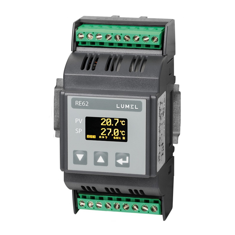
Ikony informacyjne alarmy akceptacja zmiany tryb pracy automatyczny/ręczny retransmisja aktywna autostrojenie PID aktywne zmiana wartości zadanej wysterowanie wyjścia w górę/w dół RS485 – odbiór/nadawanie (opcja) Rysunek 5. Opis panelu regulatora RE62 Rysunek 6. Opis panelu regulatora RE62... - Page 6 4. OBSłUgA Obsługa regulatora jest przedstawiona na rys. 5 Rysunek. 6. Menu obsługi regulatora...
- Page 7 W celu zmiany nastawy należy postępować wg punktu 6.3 (patrz pełna wersja instrukcji obsługi, dostepna na www. lumel.com.pl). W celu wyjścia z wybranego poziomu należy przechodzić pomiędzy parametrami aż pojawi się symbol […] i wcisnąć przycisk Aby wyjść...
- Page 8 4.2. Menu regulatora WEJŚCIE JEDNOSTKA AUTO KOMPENSACJA PRECYZJA PRZESUNIECIE KOMPENS. Parametry Jednostka Rodzaj wejścia Wartość ręcznej Precyzja Ręczne wejścia pomiarowa Włączenie kompensacji wyświetlana przesunięcie automatycznej wartości mierzonej kompensacji o zadaną wartość WYJŚCIE FUNKCJA 1 TYP 1 FUNKCJA 2 FUNKCJA 3 BŁĄD IMPULS 1/2/3 Parametry wyjść...
- Page 9 FILTR CH-KA X1 CH-KA X2 CH-KA Y1 CH-KA Y2 … Stała czasowa Charakterystyka Charakterystyka Charakterystyka Charakterystyka Przejście filtra cyfrowego indywidualna indywidualna indywidualna indywidualna poziom dla wejścia dla wejścia dla wejścia dla wejścia wyżej pomiarowego pomiarowego pomiarowego pomiarowego … Przejście poziom wyżej AUTO MAX …...
-
Page 10: Dane Techniczne
4.3. Zmiana nastawy Zmianę nastawy parametru rozpoczyna się po naciśnięciu przycisku podczas wyświetlania nazwy parametru. Przyciskami dokonuje się wyboru nastawy, a przyciskiem akcep- tuje. Anulowanie zmiany następuje po jednoczesnym naciśnięciu przy- cisków lub automatycznie po upływie około 30 sekund od ostatniego naciśnięcia dowolnego przycisku. - Page 11 Stopień ochrony: od strony czołowej IP 30 ; zacisków IP 20 Pobór mocy w obwodzie zasilania: ≤ 5 VA Masa < 0,2 kg Wymiary: 53 x 110 x 60,5 mm Znamionowe warunki użytkowania: - napięcie zasilania: 22..60 V a.c. 50..400 Hz / 20..60 V d.c. (zaciski 11-12) 60..253 V a.c.
-
Page 12: Basic Requirements, Operational Safety
2. INSTALLATION 2.1. Controller Installation Fix The RE62 controller is designed for installation in modu- lar distribution boards on a 35 mm rail. The controller housing is made of plastic. Housing dimensions: 53 x 110 x 60.5 mm. There are screw terminal strips on the outer side of the controller which enable the con- nection of external wires of diameter up to 2.5 mm... -
Page 13: Electrical Connections
Fig.1 Controller overall dimensions 2.2. Electrical Connections See page 22, fig. 2-4. 2.3. Installation Recommendations In order to obtain full noise immunity of the controller, it is recommended to observe the following principles: • do not supply the controller from the network, in the proximity of devices generating high pulse noise and do not apply common earthing circuits, •... -
Page 14: Starting To Work
• all shields should be one-side earthed or connected to the protection wire, the nearest possible to the controller, • as a rule of thumb, wires transmitting different signals should be spa- ced as far as it is possible (at least 30 cm) and should be crossed only at the right angle of 90°. - Page 15 Information icons alarms change acceptation manual / automatic working mode retransmission enabled auto-tuning function enabled change of the set value output activation up/down RS485 – reception / transmission (optional) Figure 6. RE62 controller panel description Figure 5. RE62 controller panel description...
- Page 16 RE62-09B 4. SERVICE 6. SERVICING The controller service is presented on the fig. 6 The controller service is presented in Fig. 7. Figure 7. Menu of controller s...
- Page 17 . In order to change the setting proceed acc. to the section 6.3. (see full version of service manual, available at www.lumel.com.pl). In order to exit from the selected level, transit between parameters until appears the symbol […] and press the button .
-
Page 18: Programming Matrix
4.2. Programming Matrix INPUT UNIT TYPE AUTO COMPENSATION DOT POINT OFFSET COMPENS. Input Measuring unit Input type Value of a manual Displayed Manually switch parameters Automatic compensation precision the measuring compensation value by a set enabled point OUTPUT FUNCTION 1 TYPE 1 FUNCTION 2 FUNCTION 3... - Page 19 FILTER USER CHAR. USER CHAR USER CHAR USER … CHAR Y2 Constant value Transition of the digital Individual Individual Individual Individual to the filter characteristic characteristic characteristic characteristic higher for a measuring for a measuring for a measuring for a level input input...
-
Page 20: Setting Change
4.3. Setting Change The change of parameter setting begins after pressing the button during the display of the parameter name. Buttons used for the setting choice, and the button to accept. The change cancellation follows after the simultaneous pressure of the buttons or after 30 seconds since the last button pressure. - Page 21 Serial interfaces*: RS-485, address 1..247; 8N2, 8E1, 8O1, 8N1 modes; baud rate 4.8, 9.6, 19.2 kbit/s, Broadcast address: 253 transmission protocol: modbus RTU response time: 100 ms Protection grade: from the front IP 30 ; from terminals side IP 20 Power consumption in supply circuit: ≤...
-
Page 22: Schematy Podłączeń
RS485 sygnały pomiarowe GND B RS485 Rysunek 3. Połączenia elektryczne regulatora RE62 Rys. 2. Widok listew podłączeniowych regulatora. Fig. 2. View of controller connecting strips Rysunek 3. Połączenia elektryczne regulatora RE62 1 2 3 4 5 6 1 2 3 4 5 6... - Page 23 ± 10V Resistance thermometer in 3-wire system Rysunek 4. Podłączenia sygnałów pomiarowych Rys. 3. Podłączenia sygnałów pomiarowych Fig. 3. Connections of measuring signals RE62-07B Instrukcja obsługi / load odbiornik odbiornik / load / relay OUT3 – 24 V DC, max. 40 mA OUT1, OUT2, OUT3 - przekaźnik...
- Page 24 LUMEL S.A. ul. Sulechowska 1, 65-022 Zielona Góra, Poland tel.: +48 68 45 75 100, fax +48 68 45 75 508 www.lumel.com.pl Informacja techniczna: tel.: (68) 45 75 306, 45 75 180, 45 75 260 e-mail: sprzedaz@lumel.com.pl Realizacja zamówień: tel.: (68) 45 75 207, 45 75 209, 45 75 218, 45 75 341 fax.: (68) 32 55 650...
Need help?
Do you have a question about the RE62 and is the answer not in the manual?
Questions and answers