Table of Contents
Advertisement
Quick Links
S S u u n n S S t t a a r r C C O O . . , , L L T T D D . .
R
USER ' ' S MANUAL
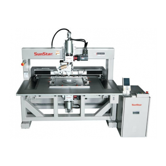
SPS/HT-5050B1 Series
Electronically Controlled
Rotary Head
Auto Pattern Sewing Machine
1) FOR AT MOST USE WITH EASINESS,
PLEASE CERTAINLY READ THIS MANUAL
BEFORE STARTING USE.
2) KEEP THIS MANUAL IN SAFE PLACE
FOR REFERENCE WHEN THE MACHINE
BREAKS DOWN.
M M M M E E - - 1 1 1 1 0 0 5 5 2 2 7 7
Advertisement
Table of Contents

Subscribe to Our Youtube Channel
Related Manuals for SunStar SPS/HT-5050B1 Series


Summary of Contents for SunStar SPS/HT-5050B1 Series
- Page 1 USER ’ ’ S MANUAL SPS/HT-5050B1 Series Electronically Controlled Rotary Head Auto Pattern Sewing Machine 1) FOR AT MOST USE WITH EASINESS, PLEASE CERTAINLY READ THIS MANUAL BEFORE STARTING USE. 2) KEEP THIS MANUAL IN SAFE PLACE FOR REFERENCE WHEN THE MACHINE BREAKS DOWN.
- Page 2 1. Thank you for purchasing our product. SunStar, with precious automation technologies and experiences from manufacturing industrial sewing machines, is committed to satisfy our clients’ demand for many types of sewing operation by manufacturing the cutting-edge electronic control pattern sewing machine with various functions, flawless performance, powerful force, improved durability.
- Page 3 PATTERN S/M Model Series Patterns SPS / HT - 50 50 B1 - 01 S S e e r r i i e e s s ( ( X X ) ) × × 1 1 0 0 m m m m S S e e w w i i n n g g r r a a n n g g e e P P u u r r p p o o s s e e s s ( ( Y Y ) ) ×...
-
Page 4: Table Of Contents
CONTENTS 1. Safety Rules ........................1) Machine movement ......................6 2) Machine installation ......................8 3) Machine operation ........................8 4) Machine operation ......................9 5) Machine troubleshooting ....................9 6) Position of caution marks ....................10 7) Contents of warning ...................... 11 2 Machine specification .................... - Page 5 10. Repairing the machine ....................1) Adjusting needle bar....................... 28 2) Adjusting needle and hook..................... 28 3) Adjustment of Presser Foot Adjusting Arm ..............29 4) Adjusting thread release and dish opening width ............29 5) Adjusting the Main Thread Control Device ..............30 6) Adjusting speed of arm lifter...................
-
Page 6: Safety Rules
Safety Rules Safety labels in the manual are categorized into danger, warning and caution. Failure to follow the safety rules may result in physical injuries or mechanical damages. : Instructions here shall be observed strictly. Otherwise, the user could suffer damage from installation, Danger movement, and repair. - Page 7 3) Using a Crane Make sure that the crane is large enough to hold the machine. Use a nylon rope of sufficient strength. Place a wooden block at either side of the machine before tying the rope. The angle should be 40° or less. Make sure that the rope does not touch the table. Nylon rope Max.
-
Page 8: Machine Installation
2) Machine installation Because physical damages such as the functional obstacles and breakdowns are likely to occur according to the environment in which the machine is being installed. Therefore, the following preconditions should be fulfilled. 1) The worktable or desk on which the machine would be installed should be strong enough to sustain the weight (see the nameplate) of the machine. -
Page 9: Machine Operation
The modification would undermine safety of the operation 3) In case of repair, you should replace the damaged part with the genuine parts of our company (SunStar). 4) After repair, please put again the safety covers disjointed during repairing. -
Page 10: Position Of Caution Marks
The labels of “Caution” are attached to the machine for safety. When operating the machine, 6) Position of caution marks make sure to follow the safety rules that each “Caution” tells. 1) Position of Caution Marks CAUTION 경 고 Do not operate without finger guard and WARNING safety devices. -
Page 11: Contents Of Warning
7) Contents of warning 1) Contents ⓐ WARNING Injury may be caused by winding. Be sure to turn off the power before cleaning, lubricating, adjusting or repairing. [ Caution ] The safety cover in the warning label refers to all covers around the operational section. -
Page 12: Machine Specification
Machine specification (SPS/HT-5050B1, 8050B1) Series SPS/HT-5050B1 SPS/HT-8050B1 Sewing range X : 500mm Y : 500mm X : 800mm Y : 500mm Max. sewing speed 2,200 spm (below 3mm of stitch length) Stitch length 0.05 ~ 12.7mm (Min. 0.05mm) Feed panel transfer method Feeding by servo motor Needle bar stroke 41.2 mm... -
Page 13: Machine Composition
Machine Composition 1) Name of parts ⑩ ③ ⑪ ⑬ ② ⑭ ⑬ ⑭ ⑨ ⑫ ⑧ ⑦ ⑮ ⑩ ① ⑤ ⑥ ④ [ Fig. 1 ] ① Power on/off ⑨ Body ② Arm ⑩ Emergency stop switch ③ Table ⑪... -
Page 14: Method Of Oil Supply
Method of oil supply 1. Before lubricating, press the safety switch of machine and supply oil. 2. Please supply oil in case of first use or not use the machine for a long time. ※ There is a danger of burning without lubricating when operating the machine. Caution 1) Oil Supply A. - Page 15 C. Supply enough oil through the oil inlet on the upper part of the arm. (One time per day, once a week) [ Fig. 4 ] D. Open a slide and supply oil to soak into a hook. E. Fill to the tank of oil of the arm (fig 2) and of the bed (fig 3) 1 time to the week, and lubricate the part superior of the arm (fig 4) and the environs of the hook (fig 5) 1 time to the day.
-
Page 16: Installing The Machine
Installing the machine 1) Conditions for installing the machine A. In order to prevent accident by malfunctioning, do not operate the machine in the place where rated voltage is more than ±10%. B. In order to prevent accident by malfunctioning, check if air pressure is proper at devices like air cylinder, before operating the machine. - Page 17 B. Table Leg Base ⓐ Put vibration-proof rubber② under the lever adjuster①. ⓑ Loosen nut③ and turn the lever adjuster① until the caster④ makes an idle rotation. ⓒ After installation, fasten nut③ to fix the lever adjuster①. ③ ④ ① ②...
- Page 18 D. Installation Methods of Defensor [ Fig. 9 ] ⓐ A Touch two parts and assemble the upper face and side using T bracket(2 Sets). ⓑ B Touch two parts and assemble the upper face and side using L bracket. ⓒ...
-
Page 19: Amp Box Installation
AMP Box Installation 1) AMP box installation Please unplug during the installation of AMP box. Plastic connector can be damaged when connecting cable, so please proceed with caution. Please lock the cover after installing AMP box not to open it arbitrarily. Caution A. -
Page 20: Amp Box Interior Cable Connection
2) AMP box interior cable connection Please check the connector color when connecting cables to the connector, then connect them to the connector of the same color. Do not pull the cables when disconnecting connector. This causes the cable disconnection. Caution A. - Page 21 C. [ Fig. 15 ] indicates the location of the main power and motor cable connection. Please refer to the next figure and table to connect the cable into the board. ① ② ③ ④ ⑤ ⑥ ⑦ ⑧ ⑨ ⑩...
- Page 22 D. [ Fig. 16 ] indicates the connection location of the pneumatic output cable and sensor input cable. Please refer to the next figure and table to connect the cable into the board. ⑥ ⑦ ⑧ ⑨ ⑩ ① ⑪ ⑫...
-
Page 23: Voltage Specifications & Change
Voltage Specifications & Change 1) Voltage specifications Do not use under the different voltage conditions. This causes the equipment damage. Caution A. SPS/HT-5050B1, 50100B1 Single-phase Three-phase Phase AC 240V AC 240V Input Voltage (V) AC 220V AC 220V AC 200V AC 200V Usable frequency : 50 / 60 Hz 2) Check voltage display LED... -
Page 24: Auxiliary Breaker Action
3) Auxiliary breaker action A. The breaker works when the input voltage becomes an overvoltage or a low-voltage. B. Please check the input voltage is consistent with the specifications. C. If the sewing machine powers on and the LED lights in green, the voltage is normal. -
Page 25: Amp Box Configuration
AMP Box Configuration 1) AMP box configuration A. Right side interior AMP box configuration Name ① ② ③ ④ ⑤ ① Head-turning upper shaft motor drive R-AMP ② Head-turning lower shaft motor drive R-AMP ⑥ ③ Lower shaft motor drive R-AMP ④... - Page 26 C. Front AMP box configuration Name ① Start switch ① ②③④ ⑦ ② Clamp movement switch ③ Emergency stop switch ⑤ ④ Thread trimming switch during sewing ⑥ ⑤ USB port ⑧ ⑥ Operation box cable entrance ⑦ Operation box ⑧...
-
Page 27: Changing Fuses
Changing Fuses To prevent electric shock, turn off the power and open the cover after five minutes. Please turn off the power and open the control box cover to change the specified capacity fuse. Caution A. Change the transformer fuse in the AMP box ⇒... -
Page 28: Repairing The Machine
Upon shipment, the machine is adjusted for the best performance. Arbitrary adjustment of the machine is not required. If some parts should need to be replaced, use only genuine parts authorized by SUNSTAR MACHINERY CO., LTD. Warning 1) Adjusting needle bar With needle bar at its lowest position, unfasten needle bar holding clamp screw ①, align, as in the Figure, upper carved... -
Page 29: Adjustment Of Presser Foot Adjusting Arm
3) Adjustment of Presser Foot Adjusting Arm A. Turn the handle of the presser foot height adjusting shaft in the A direction to make the presser foot driving link touch the B part of the arm. B. Move and fix the presser foot height adjusting arm hinge screw① to the right. C. -
Page 30: Adjusting The Main Thread Control Device
5) Adjusting the Main Thread Control Device A. If the tension control nuts① of thread control device is turned clockwise, the tension of upper thread will increase. If turned counter-clockwise, the tension will decrease. Because the tension control is affected by sewing conditions such as sewing material, thread and stitch, adjust tension according to conditions. -
Page 31: Addition Of Upper Shaft(Needle Bar) Timing Adjustment
8) Upper Shaft(Needle Bar) Timing Adjustment ⓐ Set up the up stop position of no.126 in parameter at 94。 ~96。 ⓑ Check the up stop position of thread take-up lever on the main shaft motor test. ⓒ Set up the up stop position of thread take-up lever of the upper shaft and set up the main shaft motor D Cut direction like figure. -
Page 32: Adjustment Of Needle And Hook Timing
10) Adjustment of Needle and Hook Timing ① A. Disassemble the needle plate. B. Lean the machine backward. Loosen the lower shaft collar fixing screw ① and set the needle position 2mm above the lowest position. C. Turn the hook shaft to place the hook edge at the center of the needle and tightly fasten the fixing screw ①... -
Page 33: Clearance Adjustment Of Hook And Opener
13) Clearance adjustment of hook and ⑤ opener ④ ① Bring the opener① to the hook② as close as possible and 0.5~0.7mm loosen the fixing screw③ of the opener. Adjust the opener ③ manually to allow 0.5~0.7 mm of clearance between the ⑤... -
Page 34: Trimmer
15) Trimmer ① ③ A. Trimming Order The following is the trimming order. ② ⓐ When a trimming signal is entered, as in Figure (A), ④ the trimming roller lever ① is located at the lowest <A> <B> part of the curved line of the trimmer cam. In this ①... - Page 35 C. Fixing Screw and Lower Thread Holder ⑤ ③ ⑥ ⑦ ④ When the fixed blade ① is half entered into the ① 28mm moving blade, trimming is conducted safely at the ⑧ lowest possible pressure. At the time of trimming, the lower thread holder③...
-
Page 36: Adjusting Tension Of Operating Belt
16) Adjusting tension of operating belt 1) Adjusting tension of operating belt might affect stitch quality and operation. Therefore when tension adjustment is necessary, turn to the company serviceman or an expert. 2) Make sure to turn off the power switch when adjusting tension of each operating belt. Caution A. - Page 37 b) X-conveying timing belt ① Check the X-conveying timing belt tension by detaching the upper cover of X fixing frame from the body of the machine and using sonic belt tensiometer. ② Adjust the X-conveying timing belt tension by moving the X conveying frame ① to the left end and then flipping with fingers or sticks the middle of the belt that stretches from the end of the timing belt fixing plate block ②...
-
Page 38: Setting X-Y Original Point
17) Setting X-Y Original Point 1. Please be sure to press the defensor safety switch before setting up the X-Y/rocking point of the machine. Caution A. Setting X-shaft original point. ⓐ Remove the surface cover of X-fixing frame. ⓑ Move the upper feed plate to the center of X-shaft. ⓒ... -
Page 39: Air System
C. Setting Methods of Rocking Point ⓐ Turn off the machine. ⓑ Please set up the rocking point by adjusting sensor detecting plate on the ARM / BED like figure. ⓒ Turn on the machine. [ Fig.48 ] 17) Air system Back side: Pneumatic (Assembly) position [ Fig.49 ]... -
Page 40: Preparation Before Starting Operation
1 1 1 1 Preparation before starting operation 1. Please be sure to press the safety switch before setting the machine. ※ Managers keep and use the AMP box key of the machine. In case of using the key when necessary, please press the safety switch on the AMP box to stop the machine then manage Caution maintenance. -
Page 41: How To Adjust The Upper Thread Tension
3) How to Adjust the Upper Thread Tension As in Figure, turning clockwise the tension adjustment nuts ③, ④ of the major thread control assembly ① and the ② ④ auxiliary thread control assembly ② respectively makes the upper thread tension stronger and turning counter clockwise makes it weaker. -
Page 42: Bobbin Winder
5) Bobbin Winder A. Bobbin winding ① ③ – Insert the bobbin onto the shaft ① and manually wind the ② thread 5-6 times around the bobbin. Press START button ② to wind the bobbin. – Bobbin winder will stop winding according to the embedded timer. -
Page 43: Adjustment Of Presser Foot Up/Down Stroke
Winding the bobbin off-center or uneven as shown below can cause thread breaks, skipped stitches, or thread tangles. Caution ○ Too tight tension of the bobbin winding can block smooth pulling of the thread and cause thread breaks or short tails. Caution 6) Adjustment of Presser Foot Up/Down Stroke... -
Page 44: Adjusting Upper Thread Holding Device
8) Adjusting upper thread holding device A. Check that upper thread holding pin cylinder knuckle ① is positioned in the middle of the way that upper thread follows. B. If the knuckle ① is not positioned that way as mentioned in A., unfasten the two clamp screws ③... -
Page 45: Inspection And Verification
1 1 2 2 Inspection and Verification Please clean the machine every day as follows to maintain the functions of this sewing machine and use for a long time. Even if the machine is not used for a long time, please clean and use the machine. 1) You must turn “OFF”...
Need help?
Do you have a question about the SPS/HT-5050B1 Series and is the answer not in the manual?
Questions and answers