Table of Contents
Advertisement
Available languages
Available languages
Quick Links
Therapeutic Support Surface
Surface de soutien thérapeutique
Therapeutische Auflagefläche
Therapeutisch steunoppervlak
Superficie de apoyo terapéutico
Superfície de suporte terapêutico
For Parts or Technical Assistance:
Service technique et pièces de rechange :
Für Ersatzteile oder technische Hilfe:
Voor onderdelen of technische bijstand:
Para solicitar asistencia técnica o piezas:
Para encomendar peças ou solicitar assistência técnica:
USA/États-Unis/USA/VS/EE. UU/EUA: 1-800-327-0770
2012/06 B.0
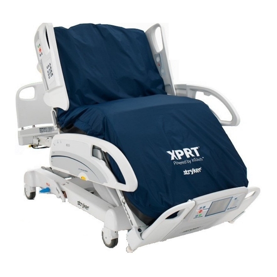
XPRT™
Operations/Maintenance Manual
2950-109-005 REV B
REF
Integrated with FL27 (2155/2156)
Intégré avec FL27 (2155/2156)
Integriert in Modell FL27 (2155/2156)
Geïntegreerd met FL27 (2155/2156)
Integración con FL27 (2155/2156)
Integrado com o FL27 (2155/2156)
Manuel d'utilisation et d'entretien
Bedienungs- und Wartungshandbuch
Gebruiks-/onderhoudshandleiding
Manual de uso y mantenimiento
Manual de funcionamento/manutenção
2950
transparent
outline with
White letters and
rectangle
0086
www.stryker.com
Advertisement
Chapters
Table of Contents

Related Manuals for Stryker XPRT 2950 Series


Summary of Contents for Stryker XPRT 2950 Series
- Page 1 Service technique et pièces de rechange : Für Ersatzteile oder technische Hilfe: Voor onderdelen of technische bijstand: Para solicitar asistencia técnica o piezas: Para encomendar peças ou solicitar assistência técnica: 0086 USA/États-Unis/USA/VS/EE. UU/EUA: 1-800-327-0770 2012/06 B.0 2950-109-005 REV B www.stryker.com...
- Page 3 FRANCE Stryker Portugal Produtos Stryker France S.A.S. Medicos, LTDA. EASTERN EUROPE ZAC - Avenue de Satolas Green Avenida Marechal Gomes Stryker SA - Export Business 69330 Pusignan da Costa, 35 Grand-Rue 90 France 1800-255 Lisboa P.O. Box 1567 Phone: 011-33-472-45-36-00...
- Page 5 To Change the Displayed Language . . . . . . . . . . . . . . . . . . . . . . . . . . . . . . . . . . . . . . . . . . . . . . . . . . . . . . . 1-29 www.stryker.com 2950-109-005 REV B...
- Page 6 Patent Information . . . . . . . . . . . . . . . . . . . . . . . . . . . . . . . . . . . . . . . . . . . . . . . . . . . . . . . . . . . . . . . . . . . . 1-72 Return To Table of Contents 2950-109-005 REV B www.stryker.com...
- Page 7 . Consult Instructions for Use Model Number Manufacturer Damp Wipe Only 10% Chlorinated Bleach Do Not Tumble Dry Do Not Iron Do Not Dry-Clean Allow to Completely Air Dry Return To Table of Contents www.stryker.com 2950-109-005 REV B...
- Page 8 . NOTE Provides special information to make maintenance easier or important instructions clearer . Return To Table of Contents 2950-109-005 REV B www.stryker.com...
- Page 9 INTENDED USE OF MANUAL This manual is designed to assist with the operation and the maintenance of the Stryker Medical 2950 XPRT™ therapeutic support surface . Carefully read thoroughly before using or beginning maintenance on the XPRT . To ensure safe operation of this equipment, it is recommended that methods and procedures be established for educating and training staff on the safe operation of the XPRT therapeutic support surface .
- Page 10 Introduction PRODUCT ILLUSTRATION Head End Head Box CPR Plug Foot End Foot Box Return To Table of Contents 2920-009-005 REV A www.stryker.com...
- Page 11 IEC60601-1 CAN/CSA C22 .2 No . 601 . 1 .-M90 Electromagnetic compatibility, meets IEC60601-1-2 (CISPR 11 classified as Class A, Group 1 ISM equipment) Return To Table of Contents www.stryker.com 2950-109-005 REV B...
- Page 12 3800 E . Centre Avenue Portage, MI 49002 Please have the serial number (A) of your Stryker product available when calling Stryker Customer Service or Technical Support . Include the serial number in all written communication . PRODUCT SERIAL NUMBER LOCATION/IDENTIFICATION The serial number (A) is located on the label located on the front of the foot box and again at (B) on the head box of the support surface as shown in Figure 1 .
- Page 13 • To avoid possible injury and to assure proper operation when using the XPRT™ therapeutic support surface on a bed frame equipped with scales or bed exit follow manufacturer’s instructions for use of these options . Return To Table of Contents www.stryker.com 2950-109-005 REV B...
- Page 14 . Do not put the support surface back into service until it is completely dry and has been thoroughly tested for safe operation . Return To Table of Contents 1-10 2950-109-005 REV B www.stryker.com...
- Page 15 Summary of Safety Precautions English CONTRAINDICATIONS Stryker Medical promotes the clinical assessment of each patient’s condition and appropriate therapy administration by the caregiver . Air support therapy is not recommended for patients with unstable fractures, unstable spinal cord injuries or those in skeletal traction .
- Page 16 Connect the air line from the support surface to the corresponding fitting on the foot box . Fasten the two (2) retaining clips to the 2 “D” Rings on foot box . Retaining “D” Ring Strap Return To Table of Contents 1-12 2950-109-005 REV B www.stryker.com...
- Page 17 2950-001-180 is disconnected or the FL27 InTouch controller is not responding, the support surface will beep to alert the user . Return To Table of Contents www.stryker.com 2950-109-005 REV B 1-13...
- Page 18 . If two therapies are simultaneously executed and a siderail is unlocked during these therapies, they will automatically stop . Return To Table of Contents 1-14 2950-109-005 REV B www.stryker.com...
- Page 19 . SLOPED HEEL SECTION The sloped heel section reduces the tissue interface pressure on the heels by providing support to the calves and redistributing the heel pressure . Return To Table of Contents www.stryker.com 2950-109-005 REV B 1-15...
- Page 20 . BED POSITIONING Raise the bed siderails . Lower the bed height to the lowest practical position . Lower the head section to flat or as low as possible . Return To Table of Contents 1-16 2950-109-005 REV B www.stryker.com...
- Page 21 . • All Therapy parameters are stored until changed or reset . • To reset the parameters to the default values, refer to “Advanced Settings” on page 1-29 . Return To Table of Contents www.stryker.com 2950-109-005 REV B 1-17...
- Page 22 Always secure the support surface to the bed frame to ensure the sensors are aligned . TO STOP ROTATION THERAPY Select the “Stop” button . The patient returns to the center position and the rotation stops . Return To Table of Contents 1-18 2950-109-005 REV B www.stryker.com...
- Page 23 . The screen will display “Percussion Started” . The screen will then display “Preparing Percussion” while the system is optimizing surface pressures for patient therapy . Return To Table of Contents www.stryker.com 2950-109-005 REV B 1-19...
- Page 24 1-29 . • The vibration therapy button is inactive while Percussion is active . TO STOP PERCUSSION THERAPY Select the “Stop” button and the percussion therapy is stopped . Return To Table of Contents 1-20 2950-109-005 REV B www.stryker.com...
- Page 25 Increase or decrease the duration of the therapy . b) Increase or decrease the intensity of the vibration . c) Select both lungs (bilateral) or either the left of right lung to receive treatment . Return To Table of Contents www.stryker.com 2950-109-005 REV B 1-21...
- Page 26 1-29 . • The Percussion therapy button is inactive while Vibration is active . TO STOP VIBRATION THERAPY Select the “Stop” button and the Vibration therapy is stopped . Return To Table of Contents 1-22 2950-109-005 REV B www.stryker.com...
- Page 27 . “Start” must be pressed to resume therapy . WARNING Deflate the XPRT™ therapeutic support surface or use Max Inflate to inflate it completely before beginning CPR . Return To Table of Contents www.stryker.com 2950-109-005 REV B 1-23...
- Page 28 Note: Rotation, Percussion and Vibration therapies are paused when Max Inflate is started . When Max Inflate is stopped, a prompt is briefly provided to continue or resume therapy . Return To Table of Contents 1-24 2950-109-005 REV B www.stryker.com...
- Page 29 Adjust the settings as needed by increasing (+) or decreasing (-) the firmness . Select the “Ok” button . PATIENT POSITIONING Align the patient’s shoulders with the graphic indicator on the side of the support surface . Return To Table of Contents www.stryker.com 2950-109-005 REV B 1-25...
- Page 30 Do not leave the patient unattended during Turn Assist . Serious injury could result . Note: The Rotation, Percussion, Vibration, Max Inflate and Firmness buttons are all inactive when Turn Assist is active . Return To Table of Contents 1-26 2950-109-005 REV B www.stryker.com...
- Page 31 Note: Rotation, Percussion and Vibration therapies are paused when Turn Assist is started . When Turn Assist is stopped, a prompt is briefly provided to continue or resume therapy . Return To Table of Contents www.stryker.com 2950-109-005 REV B 1-27...
- Page 32 • When a locked button is selected, the message “Controls Locked” is displayed . TO UNLOCK ALL FUNCTIONS Select the unlock button . The message “Controls Unlocked” will briefly display . Return To Table of Contents 1-28 2950-109-005 REV B www.stryker.com...
- Page 33 • Nederlands Note: • The selected language is active until another language is selected . • The selected language is not reset when the “Reset Parameters” button is selected . Return To Table of Contents www.stryker.com 2950-109-005 REV B 1-29...
- Page 34 Select the “Therapy History” button . Select the “Ok” button and the current therapy history is erased and reset to zero . Or select “Cancel” to retain the current therapy history . Return To Table of Contents 1-30 2950-109-005 REV B www.stryker.com...
- Page 35 Select the “Ok” button to reset all therapy parameters to the default settings . Or select “Cancel” to retain the current parameters . Note: The selected language and alarm tones are not reset . Return To Table of Contents www.stryker.com 2950-109-005 REV B 1-31...
- Page 36 Operation Guide English ADVANCED SETTINGS (CONTINUED) TO VIEW THERAPY HISTORY Select Select the “Therapy History” button . Note: The Therapy History screen is displayed for 60 seconds . Return To Table of Contents 1-32 2950-109-005 REV B www.stryker.com...
- Page 37 To end CPR and resume therapy, replace the CPR plugs until they snap back into their fully seated position . When properly seated, the “CPR Activated” on the Display will turn off . Return To Table of Contents www.stryker.com 2950-109-005 REV B 1-33...
- Page 38 Plug the bed power cord into properly grounded, hospital grade wall receptacles when the patient’s destination is reached . Plug the support surface power cord into the FL27 . Note: The support surface will automatically maintain air pressure for up to four hours . Return To Table of Contents 1-34 2950-109-005 REV B www.stryker.com...
- Page 39 Check patient frequently to ensure proper positioning and support surface inflation . 12 . Align the patient’s shoulders with the graphic indicator on the side of the support surface . 13 . Raise and lock the siderails . Return To Table of Contents www.stryker.com 2950-109-005 REV B 1-35...
- Page 40 . • Disinfect the support surface between patients . Failure to properly disinfect could result in cross-contamination and infection . • Consult physician if redness or skin breakdown occurs . Return To Table of Contents 1-36 2950-109-005 REV B www.stryker.com...
- Page 41 ____ Foam/air cells are free of excessive wear (i .e . cracks) . Recommend checking cells every 6 months . Replace, if necessary . Support Surface Serial No. Completed by:_________________________ Date________________________________ Return To Table of Contents www.stryker.com 2950-109-005 REV B 1-37...
- Page 42 WARNING Allow the foot box to completely dry before placing the support surface over it . Excess moisture could cause equipment malfunction resulting in equipment damage or patient injury . Return To Table of Contents 1-38 2950-109-005 REV B www.stryker.com...
- Page 43 1) If no voltage at any one of the points, check for 26 VAC on connector J2 . If no voltage, replace the transformer and contact your local Stryker service representative to return for fault evaluation . 2) If no voltage at any one of the points, replace the power board and contact your local Stryker service representative to return for fault evaluation .
- Page 44 . B . Check the red connector for a proper connection . If it is connected properly, test with another controller . Return To Table of Contents 1-40 2950-109-005 REV B www.stryker.com...
- Page 45 Product Labels English XPRT Pulmonary Mattress STRYKER MEDICAL 3800 East Centre Ave. 2155/2156 (2950200002) Portage, MI 49002 USA 2011 CAUTION U.S.Federal law restricts this device to sale by or on the order of a physician. For grounding reliability, plug only into a...
- Page 46 Fasten 2 Retaining Strap Clips to 2 Linens should remain loose and wrinkly on D-Rings on foot box. surface of mattress. P/N 13051000 5/06 Return To Table of Contents 1-42 2950-109-005 REV B www.stryker.com...
- Page 47 The parts and accessories listed on this page are all currently available for purchase . Some of the parts identified on the assembly drawing parts in this manual may not be individually available for purchase . Please call Stryker Customer Service USA: 1-800-327-0770 for availability and pricing .
- Page 48 Using a Phillips screwdriver, remove the six screws holding the power board to the foot box assembly . Remove the power board and contact your local Stryker service representative to return for fault evaluation . Reverse the procedure to install the new power board .
- Page 49 (D) securing the pump assembly to the bottom of the foot box (Figure 3) . Save the machine screws for later reinstallation . Figure 1 Figure 2 Figure 3 Return To Table of Contents www.stryker.com 2950-109-005 REV B 1-45...
- Page 50 3 (see Figure 1) . 18 . Fold the foot end of the support surface back down . 19 . Test the support surface functionality before returning to service . Figure 7 Return To Table of Contents 1-46 2950-109-005 REV B www.stryker.com...
- Page 51 Using a Phillips screwdriver, remove the eight screws securing the CPU board to the head box and contact your local Stryker service representative to return for fault evaluation . 10 . Reverse the procedure to install the new CPU board .
- Page 52 Install the new stepper motor / rotary valve assembly and reverse the steps . 10 . Plug the support surface power cord into the power source and test the functionality before returning to service . Return To Table of Contents 1-48 2950-109-005 REV B www.stryker.com...
- Page 53 Cut spiral tubing just above 90 degree fitting from head box, four places . Refer to Figure 1 . Figure 1 Remove existing 90 degree fittings from head box and replace with new 90 degree fittings, four places . Refer to Figure 2 for orientation . Figure 2 Return To Table of Contents www.stryker.com 2950-109-005 REV B 1-49...
- Page 54 Cut tubing just above the 90 degree fitting from the head box; two places . Refer to Figure 4 . Figure 4 Remove existing 90 degree fittings from head box and replace with new 90 degree fittings, two places . Refer to Figure 5 for orientation . Figure 5 Return To Table of Contents 1-50 2950-109-005 REV B www.stryker.com...
- Page 55 Note: Two people required to return support surface to original flat position . Unsnap cell-retaining strap from cell assembly near foot end as shown in Figure 6 . 10 . Remove Cell Assembly and contact your local Stryker service representative to return for fault evaluation . Figure 6 INSTALLATION OF NEW CELL ASSEMBLY Place new cell assembly on top of foam crib .
- Page 56 . Refer to Figure 10 . Return head end of support surface down to original flat position . Note: Two people required to fold back foam crib and head box . Figure 10 Return To Table of Contents 1-52 2950-109-005 REV B www.stryker.com...
- Page 57 14 . Put the support surface into the service mode . (Lock Screen, Hold Percussion 5 seconds, Hold Rotation 5 seconds, Press Start) . 15 . Perform a diagnostic test to verify the support surface is working correctly . Return To Table of Contents www.stryker.com 2950-109-005 REV B 1-53...
- Page 58 Select and hold the “Rotation” button for approximately five seconds until the service welcome displays on the footboard display . Select the “Start” button to enter the service screen . Return To Table of Contents 1-54 2950-109-005 REV B www.stryker.com...
- Page 59 Result of Diagnostic Test . Shows no values until the Diagnostic Test is run . Values update as tests are executed . Over temperature status . Service/Error log . Displays service codes and descriptions . Press up or down buttons to scroll through the list of events/errors . Return To Table of Contents www.stryker.com 2950-109-005 REV B 1-55...
- Page 60 Do not perform Burn In function in the field, this function is for ‘manufacturing’ purposes only . Press the “Restart Log” button to update event information from the CPU . Use when replacing a controller . Return To Table of Contents 1-56 2950-109-005 REV B www.stryker.com...
- Page 61 Press the “Reset Service Error/Log” button to clear the service error log . Press the “Cancel” button to cancel any of the service screen functions and return to the therapy menu . Return To Table of Contents www.stryker.com 2950-109-005 REV B 1-57...
- Page 62 Check connector is fully engaged to PCB TB6 . CPR_Both Both CPR plugs are not detected . Check CPR plugs are fully engaged and snapped . Check connector is fully engaged to PCB TB6 . Return To Table of Contents 1-58 2950-109-005 REV B www.stryker.com...
- Page 63 > 140 degrees F (60 degrees C) . motor . Displays message “Auto . Overload Check percussion motor belt tension . Caused a Power Shutdown . ” Check connecting rod bearing . Return To Table of Contents www.stryker.com 2950-109-005 REV B 1-59...
- Page 64 (TB9) of less than 0 .2 volts DC when the flag is aligned with the sensor and greater than 4 .0 volts DC when not aligned . Replace sensor if necessary . Return To Table of Contents 1-60 2950-109-005 REV B www.stryker.com...
- Page 65 Check for kinked supply tubing in support surface and replace with wire reinforced supply tubing and clamps if necessary . Check for plugged bulkhead fitting at foot box and replace if necessary . Return To Table of Contents www.stryker.com 2950-109-005 REV B 1-61...
- Page 66 Rotary valve stopped at the wrong an air cell that is not intended to be position and is filling the wrong cell . filling . Check tubing for proper connections . Return To Table of Contents 1-62 2950-109-005 REV B www.stryker.com...
- Page 67 . rotation cells . This alarm is more susceptible when the rotation rate is set very low, there is patient movement or no patient on the support surface . Return To Table of Contents www.stryker.com 2950-109-005 REV B 1-63...
- Page 68 The system lost power and restarted . 1 . This is not an error message rather an indication that the system lost power and then the power was reapplied . Return To Table of Contents 1-64 2950-109-005 REV B www.stryker.com...
- Page 69 Diagnostic test leak rotation bladder circuit . LEFT_PERCUSSION_LEAK Diagnostic test leak percussion bladder circuit . RIGHT_PERCUSSION_LEAK Diagnostic test leak percussion bladder circuit . INVALID_COMMAND An invalid command has been received by the support surface controller . Return To Table of Contents www.stryker.com 2950-109-005 REV B 1-65...
- Page 70 Assembly Part number: 2950-047-000 (Reference Only) Head Box Assembly Item Recycling/Material Code Important Information (2950-001-225) Valve Solenoid 24 VDC (2950-001-224) Sensor Solenoid 24 VDC (2950-101-223) PCB, Main Control Board Assembly Return To Table of Contents 1-66 2950-109-005 REV B www.stryker.com...
- Page 71 Recycling Passports English Assembly Part number: 2950-003-007 (Reference Only) Foot Box Assembly Item Recycling/Material Code Important Information (2950-001-116) Power Supply Board (2950-001-119) Transformer Assembly (2950-001-123) EMI Power Line Filter Return To Table of Contents www.stryker.com 2950-109-005 REV B 1-67...
- Page 72 IEC 61000-4-8 characteristic typical location in a typical commercial and/or hospital environment . Note: U is the a .c . mains voltage prior to applications of the test level . Return To Table of Contents 1-68 2950-109-005 REV B www.stryker.com...
- Page 73 At 80 MHz and 800 MHz, the separation distance for the higher frequency range applies . NOTE 2 These guidelines may not apply in all situations . Electromagnetic propagation is affected by absorption and reflection from structures, objects and people . Return To Table of Contents www.stryker.com 2950-109-005 REV B 1-69...
- Page 74 XPRT™ . Over the frequency range 150 kHz to 80 MHz, field strengths are less than 3 V/m . Return To Table of Contents 1-70 2950-109-005 REV B www.stryker.com...
- Page 75 Class A CISPR 11 low voltage power supply network that supplies buildings used for domestic purposes . Harmonic Emissions Class A IEC 61000-3-2 Voltage Fluctuations Flicker Emissions Complies IEC 61000-3-3 Return To Table of Contents www.stryker.com 2950-109-005 REV B 1-71...
- Page 76 Stryker’s obligation under this warranty is expressly limited to supplying replacement parts and labor for, or replacing, at its option, any product which is, in the sole discretion of Stryker, found to be defective . If requested by Stryker, products or parts for which a warranty claim is made shall be returned prepaid to the factory . Any improper use or any alteration or repair by others in such manner as in Stryker’s judgment affects the product materially and adversely...
- Page 77 Changement de la langue d’affichage . . . . . . . . . . . . . . . . . . . . . . . . . . . . . . . . . . . . . . . . . . . . . . . . . . . . . .2-29 www.stryker.com 2950-109-005 REV B...
- Page 78 Informations sur les brevets . . . . . . . . . . . . . . . . . . . . . . . . . . . . . . . . . . . . . . . . . . . . . . . . . . . . . . . . . . . . .2-72 Retour à la table des matières 2950-109-005 REV B www.stryker.com...
- Page 79 Essuyer avec un linge humide Eau de Javel à 10 % Ne pas sécher au sèche-linge Ne pas repasser . Ne pas nettoyer à sec . Laisser sécher complètement à l’air . Retour à la table des matières www.stryker.com 2950-109-005 REV B...
- Page 80 . Couvre notamment les précautions à prendre afin d’assurer l’utilisation sûre et efficace du matériel et d’éviter les dommages qui pourraient découler de l’usage ou d’une utilisation incorrecte du matériel . REMARQUE Fournit des informations spécifiques destinées à faciliter l’entretien ou à clarifier des instructions importantes . Retour à la table des matières 2950-109-005 REV B www.stryker.com...
- Page 81 UTILISATION PRÉVUE DE CE MANUEL Ce manuel est conçu pour décrire le fonctionnement et l’entretien de la surface de soutien thérapeutique Stryker Medical 2950 XPRT™ . Lire attentivement et intégralement ce manuel avant d’utiliser ou de procéder à l’entretien du système XPRT .
- Page 82 Introduction ILLUSTRATION DU PRODUIT Côté tête Boîte côté tête Français Bouchon de RCP Côté pieds Boîte côté pieds Retour à la table des matières 2950-109-005 REV B www.stryker.com...
- Page 83 C22 .2 No . 601 . 1 .-M90 . Compatibilité électromagnétique, conforme à la norme IEC 60601-1-2 (classé par le CISPR 11 comme matériel ISM de classe A, groupe 1) Retour à la table des matières www.stryker.com 2950-109-005 REV B...
- Page 84 3800 E . Centre Avenue Portage, MI 49002 Garder le numéro de série (A) du produit Stryker à portée de main avant d’appeler le service clientèle ou le support technique de Stryker . Inclure le numéro de série dans toutes les communications écrites .
- Page 85 • Pour éviter d’éventuelles blessures et garantir le bon fonctionnement de la surface de soutien thérapeutique XPRT™ sur un châssis de lit équipé d’un système de pesée ou d’une sortie de lit, suivre les instructions du fabricant lors de l’utilisation de ces options . Retour à la table des matières www.stryker.com 2950-109-005 REV B...
- Page 86 . Ne pas remettre la surface de soutien en service avant qu’elle soit complètement sèche et que la sécurité de son fonctionnement ait été soigneusement testée . Retour à la table des matières 2-10 2950-109-005 REV B www.stryker.com...
- Page 87 Résumé des précautions d’emploi CONTRE-INDICATIONS Stryker Medical recommande une évaluation clinique de chaque patient et une administration appropriée du traitement par le personnel soignant . Le support thérapeutique à air n’est pas recommandé chez les patients présentant des fractures instables, des lésions instables de la moelle épinière ou traités par traction squelettique .
- Page 88 Raccorder le tuyau à air de la surface de soutien au raccord correspondant de la boîte du côté pieds . Fixer les deux (2) clips de retenue aux 2 anneaux en D de la boîte côté pieds . Retour à la table des matières 2-12 2950-109-005 REV B www.stryker.com...
- Page 89 émet un bip pour alerter l’utilisateur si le câble adaptateur 2950-001-180 est déconnecté ou si le contrôleur FL27 InTouch ne réagit pas . Retour à la table des matières www.stryker.com 2950-109-005 REV B 2-13...
- Page 90 Si une barrière est déverrouillée pendant le traitement rotation, traitement s’arrête automatiquement . Si deux traitements sont effectués simultanément et qu’une barrière est déverrouillée pendant leur exécution, ils s’arrêtent automatiquement . Retour à la table des matières 2-14 2950-109-005 REV B www.stryker.com...
- Page 91 SECTION TALONS LÉGÈREMENT INCLINÉE La section talons, légèrement inclinée, réduit la pression au niveau de l’interface cutanée des talons en soutenant les mollets et en redistribuant la pression des talons . Retour à la table des matières www.stryker.com 2950-109-005 REV B 2-15...
- Page 92 Relever les barrières du lit . Abaisser la hauteur du lit jusqu’à la position la plus basse qui soit pratique . Abaisser la section tête à plat ou aussi bas que possible . Retour à la table des matières 2-16 2950-109-005 REV B www.stryker.com...
- Page 93 . • Pour réinitialiser les paramètres aux valeurs par défaut, se référer à « Réglages avancés » à la page 2-29 . Retour à la table des matières www.stryker.com 2950-109-005 REV B 2-17...
- Page 94 . ARRÊT DU TRAITEMENT PAR ROTATION Sélectionner « Stop » . Le patient revient en position centrée et la rotation s’arrête . Retour à la table des matières 2-18 2950-109-005 REV B www.stryker.com...
- Page 95 L’écran affiche « Percussion Started » (Percussion en route) . L’écran affiche ensuite « Preparing Percussion » (Préparation de la percussion) tandis que le système optimise les pressions de surface pour le traitement du patient . Retour à la table des matières www.stryker.com 2950-109-005 REV B 2-19...
- Page 96 • La touche de traitement par vibration est désactivée quand le mode Percussion est en cours . ARRÊT DU TRAITEMENT PAR PERCUSSION Sélectionner « Stop » et le traitement par percussion s’arrête . Retour à la table des matières 2-20 2950-109-005 REV B www.stryker.com...
- Page 97 Augmenter ou diminuer la durée du traitement . b) Augmenter ou diminuer l’intensité de la vibration . c) Sélectionner les deux poumons (« Bilateral ») ou le poumon gauche ou droit devant recevoir le traitement . Retour à la table des matières www.stryker.com 2950-109-005 REV B 2-21...
- Page 98 • La touche de traitement par percussion est désactivée quand le mode Vibration est en cours . ARRÊT DU TRAITEMENT PAR VIBRATION Sélectionner « Stop » et le traitement par vibration s’arrête . Retour à la table des matières 2-22 2950-109-005 REV B www.stryker.com...
- Page 99 . AVERTISSEMENT Dégonfler la surface de soutien thérapeutique XPRT™ ou utiliser la fonction Max Inflate (Gonflage maximum) pour la gonfler entièrement avant de commencer la RCP . Retour à la table des matières www.stryker.com 2950-109-005 REV B 2-23...
- Page 100 Max Inflate (Gonflage maximum) est mis en route . Quand la fonction est arrêtée, un message s’affiche momentanément, demandant à l’utilisateur s’il souhaite continuer ou reprendre le traitement . Français Retour à la table des matières 2-24 2950-109-005 REV B www.stryker.com...
- Page 101 (-) la fermeté . Sélectionner « OK » . POSITIONNEMENT DU PATIENT Aligner les épaules du patient avec l’indicateur graphique situé sur le côté de la surface de soutien . Retour à la table des matières www.stryker.com 2950-109-005 REV B 2-25...
- Page 102 . Remarque : Les touches Rotation, Percussion, Vibration, Max Inflate (Gonflage maximum) et Firmness (Fermeté) sont toutes désactivées quand la fonction Turn Assist (Retournement assisté) est en cours . Retour à la table des matières 2-26 2950-109-005 REV B www.stryker.com...
- Page 103 (Retournement assisté) est mis en route . Quand la fonction Turn Assist (Retournement assisté) est arrêtée, un message s’affiche momentanément, demandant à l’utilisateur s’il souhaite continuer ou reprendre le traitement . Retour à la table des matières www.stryker.com 2950-109-005 REV B 2-27...
- Page 104 « Controls Locked » (Commandes verrouillées) s’affiche . Français DÉVERROUILLAGE DE TOUTES LES FONCTIONS Sélectionner le bouton de déverrouillage Le message « Controls Unlocked » (Commandes déverrouillées) s’affiche momentanément . Retour à la table des matières 2-28 2950-109-005 REV B www.stryker.com...
- Page 105 • La langue sélectionnée est active jusqu’à ce qu’une autre langue soit sélectionnée . • La langue sélectionnée n’est pas réinitialisée quand la touche « Reset Parameters » (Réinitialiser les paramètres) est sélectionnée . Retour à la table des matières www.stryker.com 2950-109-005 REV B 2-29...
- Page 106 Sélectionner « OK » et l’historique de traitement actuel est effacé et réinitialisé à zéro . Ou sélectionner « Cancel » (Annuler) pour enregistrer l’historique de traitement actuel . Retour à la table des matières 2-30 2950-109-005 REV B www.stryker.com...
- Page 107 . Ou sélectionner « Cancel » (Annuler) pour enregistrer les paramètres actuels . Remarque : La langue et les tonalités d’alarme sélectionnées ne sont pas réinitialisées . Retour à la table des matières www.stryker.com 2950-109-005 REV B 2-31...
- Page 108 AFFICHAGE DE L’HISTORIQUE DE TRAITEMENT Sélectionner Sélectionner « Therapy History » (Historique de traitement) . Remarque : L’écran Therapy History (Historique de traitement) s’affiche pendant 60 secondes . Français Retour à la table des matières 2-32 2950-109-005 REV B www.stryker.com...
- Page 109 Pour terminer la RCP et reprendre le traitement, replacer les bouchons de RCP jusqu’à ce qu’ils soient complètement renfoncés . Lorsqu’ils sont correctement renfoncés, « CPR Activated » (RCP vactivée) disparaît de l’écran . Retour à la table des matières www.stryker.com 2950-109-005 REV B 2-33...
- Page 110 Brancher le cordon d’alimentation de la surface de soutien au FL27 . Remarque : La surface de soutien maintient automatiquement la pression d’air pendant quatre heures au maximum . Retour à la table des matières 2-34 2950-109-005 REV B www.stryker.com...
- Page 111 . 12 . Aligner les épaules du patient avec l’indicateur graphique situé sur le côté de la surface de soutien . 13 . Relever et verrouiller les barrières . Retour à la table des matières www.stryker.com 2950-109-005 REV B 2-35...
- Page 112 • Désinfecter la surface de soutien entre deux patients . Le non-respect de cette consigne risque d’entraîner une contamination croisée et une infection . • Consulter un médecin en cas de rougeurs ou de détérioration cutanée . Retour à la table des matières 2-36 2950-109-005 REV B www.stryker.com...
- Page 113 ____ Les cellules en mousse/à air ne sont pas excessivement usées (c .-à-d . sans fissures) . Il est recommandé de contrôler les cellules tous les 6 mois . Remplacez si nécessaire . Numéro de série de la surface de soutien Rempli par :_________________________ Date________________________________ Retour à la table des matières www.stryker.com 2950-109-005 REV B 2-37...
- Page 114 Laisser complètement sécher la boîte côté pieds avant de placer la surface de soutien dessus . Une humidité excessive peut entraîner une défaillance du matériel qui risque d’endommager le matériel ou de provoquer des blessures chez le patient . Retour à la table des matières 2-38 2950-109-005 REV B www.stryker.com...
- Page 115 2) Si la tension est absente à l’un de ces points, remplacer la carte d’alimentation et contacter un représentant du service technique Stryker local afin de renvoyer la carte pour une évaluation de la panne . Si la surface de soutien est à présent alimentée, la remettre en service .
- Page 116 . Si la surface de soutien est à présent alimentée, la remettre en service . B . Vérifier que le connecteur rouge est bien connecté . S’il est correctement raccordé, tester avec un autre contrôleur . Retour à la table des matières 2-40 2950-109-005 REV B www.stryker.com...
- Page 117 Étiquettes du produit XPRT Pulmonary Mattress STRYKER MEDICAL 3800 East Centre Ave. 2155/2156 (2950200002) Portage, MI 49002 USA 2011 MISE EN GARD Selon la loi fédérale des États-Unis, ce dispositif ne peut être vendu que par un médecin ou sur sa prescription. Pour assurer la abilité...
- Page 118 2 anneaux en D sur la boîte du côté pieds. tirant. Les draps doivent être lâches et des plis visibles sur la surface du matelas. N° de pièce :/13051000 5/06 Retour à la table des matières 2-42 2950-109-005 REV B www.stryker.com...
- Page 119 Tous les accessoires et pièces répertoriés sur cette page sont actuellement disponibles à la vente . Certaines des pièces indiquées sur les vues éclatées de ce manuel peuvent ne pas être disponibles individuellement . Merci d’appeler le service client Stryker aux États-Unis : 1-800-327-0770 pour la disponibilité et les prix . Dénomination de la pièce Référence...
- Page 120 À l’aide d’un tournevis cruciforme, retirer les six vis qui fixent la carte d’alimentation sur l’assemblage de la boîte côté pieds . Retirer la carte d’alimentation et contacter un représentant du service technique Stryker local afin de renvoyer la carte pour une évaluation de la panne .
- Page 121 à métaux (D) fixant le bloc de pompe au fond de la boîte côté pieds (Figure 3) . Conserver les vis à métaux pour la réinstallation ultérieure . Figure 1 Figure 2 Figure 3 Retour à la table des matières www.stryker.com 2950-109-005 REV B 2-45...
- Page 122 18 . Replier le côté pieds de la surface de soutien vers le bas . Figure 7 19 . Tester le fonctionnement de la surface de soutien avant de la remettre en service . Retour à la table des matières 2-46 2950-109-005 REV B www.stryker.com...
- Page 123 À l’aide d’un tournevis cruciforme, retirer les huit vis cruciformes qui fixent la carte UC sur la boîte côté tête et contacter un représentant du service technique Stryker local afin de renvoyer la carte pour une évaluation de la panne .
- Page 124 10 . Brancher le cordon d’alimentation de la surface de soutien dans la source d’alimentation et tester les fonctions de la surface de soutien avant de la remettre en service . Retour à la table des matières 2-48 2950-109-005 REV B www.stryker.com...
- Page 125 Retirer les raccords à 90° existants de la boîte côté tête et les remplacer par de nouveaux raccords à 90°, en quatre emplacements . Consulter la Figure 2 pour l’orientation . Figure 2 Retour à la table des matières www.stryker.com 2950-109-005 REV B 2-49...
- Page 126 Retirer les raccords à 90° existants de la boîte côté tête et les remplacer par de nouveaux raccords à 90°, en deux emplacements . Consulter la Figure 5 pour l’orientation . Figure 5 Retour à la table des matières 2-50 2950-109-005 REV B www.stryker.com...
- Page 127 9 . Défaire la sangle de retenue des cellules de l’assemblage de cellule près du côté pieds, tel qu’illustré dans la Figure 6 . 10 . Retirer l’assemblage de cellule et contacter un représentant du service technique Stryker local afin de le renvoyer pour une évaluation de la panne .
- Page 128 Remettre le côté tête de la surface de soutien à plat, dans sa position d’origine . Remarque : deux personnes sont nécessaires pour replier le caisson en mousse et la boîte côté tête . Figure 10 Retour à la table des matières 2-52 2950-109-005 REV B www.stryker.com...
- Page 129 Rotation pendant 5 secondes, appuyer sur « Start » [Démarrage] . ) 15 . Exécuter un test diagnostique pour vérifier que la surface de soutien fonctionne correctement . Retour à la table des matières www.stryker.com 2950-109-005 REV B 2-53...
- Page 130 Sélectionner et maintenir la touche « Rotation » enfoncée pendant cinq secondes environ jusqu’à ce que le repose-pied affiche l’accueil de service . Sélectionner « Start » (Démarrage) pour accéder à l’écran Service . Retour à la table des matières 2-54 2950-109-005 REV B www.stryker.com...
- Page 131 à mesure que les tests sont accomplis . État de surchauffe . Journal de service/erreurs . Affiche les codes et descriptions de service . Appuyer sur pour faire défiler la liste des événements/erreurs . Retour à la table des matières www.stryker.com 2950-109-005 REV B 2-55...
- Page 132 : cette fonction est réservée à des fins de fabrication . Appuyer sur « Restart Log » (Relancer Journal) pour mettre à jour les informations d’événement de l’UC . Utiliser lors du remplacement du contrôleur . Retour à la table des matières 2-56 2950-109-005 REV B www.stryker.com...
- Page 133 Journal de service/erreurs) pour effacer le journal de service/erreurs . Français Appuyer sur « Cancel » (Annuler) pour annuler une fonction quelconque de l’écran Service et retourner au menu du traitement . Retour à la table des matières www.stryker.com 2950-109-005 REV B 2-57...
- Page 134 Les deux bouchons de RCP ne sont Vérifier que les bouchons de RCP sont pas détectés . complètement enfoncés et enclenchés . Vérifier que le connecteur est complètement enfoncé dans la CCI TB6 . Retour à la table des matières 2-58 2950-109-005 REV B www.stryker.com...
- Page 135 Vérifier la tension de courroie du moteur à Shutdown . » (Mise hors tension pour percussion . cause de surcharge auto . ) est affiché . Vérifier le palier de la biellette de connexion . Retour à la table des matières www.stryker.com 2950-109-005 REV B 2-59...
- Page 136 (TB9) quand le drapeau est aligné sur le capteur et une tension supérieure à 4,0 volts CC quand le drapeau n’est pas aligné . Remplacer le capteur selon les besoins . Retour à la table des matières 2-60 2950-109-005 REV B www.stryker.com...
- Page 137 à renfort métallique et des pinces . Vérifier que le raccord de cloison n’est pas bouché au niveau de la boîte côté pieds et le remplacer selon les besoins . Retour à la table des matières www.stryker.com 2950-109-005 REV B 2-61...
- Page 138 La vanne rotative s’est arrêtée dans la mauvaise Reading dans une cellule à air qui n’est pas position et gonfle la mauvaise cellule . supposée se gonfler . Vérifier que la tubulure est correctement connectée . Retour à la table des matières 2-62 2950-109-005 REV B www.stryker.com...
- Page 139 Cette alarme est plus susceptible de se déclencher quand la fréquence de rotation est réglée très bas, en présence de mouvement du patient ou en l’absence d’un patient sur la surface de soutien . Retour à la table des matières www.stryker.com 2950-109-005 REV B 2-63...
- Page 140 L’alimentation du système a été Ceci n’est pas un message d’erreur mais Occurred coupée puis rétablie . indique une coupure de l’alimentation du système, suivie de son rétablissement . Français Retour à la table des matières 2-64 2950-109-005 REV B www.stryker.com...
- Page 141 Fuite du circuit de la vessie de percussion au cours du test diagnostique . INVALID_COMMAND Une commande non valide a été reçue par le contrôleur de la surface de soutien . Retour à la table des matières www.stryker.com 2950-109-005 REV B 2-65...
- Page 142 Assembly Part number: 2950-047-000 (Reference Only) Head Box Assembly Français Item Recycling/Material Code Important Information (2950-001-225) Valve Solenoid 24 VDC (2950-001-224) Sensor Solenoid 24 VDC (2950-101-223) PCB, Main Control Board Assembly Retour à la table des matières 2-66 2950-109-005 REV B www.stryker.com...
- Page 143 Recycling Passports Assembly Part number: 2950-003-007 (Reference Only) Français Foot Box Assembly Item Recycling/Material Code Important Information (2950-001-116) Power Supply Board (2950-001-119) Transformer Assembly (2950-001-123) EMI Power Line Filter Retour à la table des matières www.stryker.com 2950-109-005 REV B 2-67...
- Page 144 . Remarque : U représente la tension du secteur (CA) avant l’application du niveau de test . Retour à la table des matières 2-68 2950-109-005 REV B www.stryker.com...
- Page 145 Il est possible que ces directives ne s’appliquent pas à toutes les situations . La propagation électromagnétique est modifiée par l’absorption et la réflexion sur les structures, les objets et les personnes . Retour à la table des matières www.stryker.com 2950-109-005 REV B 2-69...
- Page 146 être nécessaires, telles que la réorientation ou le déplacement du XPRT™ . Dans la plage de fréquences de 150 kHz à 80 MHz, les intensités des champs sont inférieures à 3 V/m . Retour à la table des matières 2-70 2950-109-005 REV B www.stryker.com...
- Page 147 CISPR 11 public basse tension alimentant les bâtiments à usage domestique . Émissions harmoniques Classe A CEI 61000-3-2 Fluctuations de tension Émissions dues aux oscilla- Conforme tions (flicker) CEI 61000-3-3 Retour à la table des matières www.stryker.com 2950-109-005 REV B 2-71...
- Page 148 XPRT™ sera exempt de vices matériels et de fabrication pendant une période de deux (2) ans à compter de la date de livraison . L’obligation de Stryker en vertu de la présente garantie se limite expressément, au gré de la société, à...
- Page 149 Ändern der angezeigten Sprache . . . . . . . . . . . . . . . . . . . . . . . . . . . . . . . . . . . . . . . . . . . . . . . . . . . . . . . . . . . . . www.stryker.com...
-
Page 150: Table Of Contents
Patentangaben . . . . . . . . . . . . . . . . . . . . . . . . . . . . . . . . . . . . . . . . . . . . . . . . . . . . . . . . . . . . . . . . . . . . . . . . . . Zurück zum Inhaltsverzeichnis 2950-109-005 REV B www.stryker.com... - Page 151 . Auskünfte über länderspezifische Rückgabe- und/oder Sammelsysteme sind beim jeweiligen Händler erhältlich . Gebrauchsanweisung beachten Modellnummer Hersteller Nur feucht abwischen 10%-ige Chlorbleichelösung Nicht im Wäschetrockner trocknen Nicht bügeln Nicht chemisch reinigen Vollständig an der Luft trocknen lassen Zurück zum Inhaltsverzeichnis www.stryker.com 2950-109-005 REV B...
- Page 152 Systems und die nötigen Vorsichtsmaßnahmen, um Beschädigungen des Systems zu vermeiden, die als Folge des Gebrauchs bzw . der unsachgemäßen Benutzung auftreten könnten . HINWEIS Enthält Informationen, die die Wartung erleichtern oder wichtige Anweisungen verdeutlichen . Zurück zum Inhaltsverzeichnis 2950-109-005 REV B www.stryker.com...
- Page 153 Dieses Handbuch wurde entworfen, um bei der Bedienung und Wartung der therapeutischen XPRT™-Auflagefläche, Modell 2950, von Stryker Medical behilflich zu sein . Vor Verwendung der XPRT-Auflagefläche bzw . vor der Durchführung von Wartungsarbeiten gründlich lesen . Zur Gewährleistung des sicheren Betriebs dieses Geräts wird empfohlen, Methoden und Maßnahmen zur Information und Schulung von Personal über die sichere Bedienung der therapeutischen XPRT-Auflagefläche...
- Page 154 Einführung PRODUKTABBILDUNG Kopfende Kopfende-Schaltkasten Deutsch HLR-Stecker Fußende Fußende-Schaltkasten Zurück zum Inhaltsverzeichnis 2950-109-005 REV B www.stryker.com...
- Page 155 Medizingerät: Klassifikation nur in Bezug auf Stromschlag und mechanische Gefahren, gemäß IEC 60601-1 CAN/CSA C22 .2 No . 601 . 1 .-M90 Elektromagnetische Verträglichkeit, erfüllt IEC 60601-1-2 (CISPR 11 Klassifikation als ISM-Gerät der Klasse A, Gruppe 1) Zurück zum Inhaltsverzeichnis www.stryker.com 2950-109-005 REV B...
- Page 156 3800 E . Centre Avenue Portage, MI 49002 Deutsch Bei Anrufen beim Stryker-Kundendienst oder technischen Support bitte die Seriennummer (A) des jeweiligen Stryker-Produkts bereithalten . Die Seriennummer bei allen schriftlichen Mitteilungen angeben . IDENTIFIZIERUNG/ORT DER PRODUKTSERIENNUMMER Die Seriennummer (A) befindet sich auf dem Etikett auf der Vorderseite des Fußende-Schaltkastens und noch einmal (B) am Kopfende-Schaltkasten der Auflagefläche (siehe Abbildung 1) .
- Page 157 Bei der Verwendung der therapeutischen XPRT™-Auflagefläche auf einem mit Waage oder der Funktion „Bed Exit“ (Bettenausstieg) ausgestatteten Bettrahmen immer den Anweisungen des Herstellers bez . dieser Funktionen folgen, um mögliche Verletzungen zu vermeiden und einen ordnungsgemäßen Betrieb zu gewährleisten . Zurück zum Inhaltsverzeichnis www.stryker.com 2950-109-005 REV B...
- Page 158 Komponenten führen und einen unzuverlässigen Betrieb der Auflagefläche oder den kompletten Ausfall einiger Funktionen verursachen . Bevor die Auflagefläche nicht vollständig getrocknet ist und gründlich auf sicheren Betrieb getestet wurde, darf sie nicht wieder benutzt werden . Zurück zum Inhaltsverzeichnis 3-10 2950-109-005 REV B www.stryker.com...
- Page 159 Zusammenfassung der Sicherheitsvorkehrungen KONTRAINDIKATIONEN Stryker Medical fördert die klinische Beurteilung des Zustands von jedem Patienten und die geeignete Therapieanwendung durch das Pflegepersonal . Eine Luftunterstützungstherapie wird bei Patienten mit instabilen Frakturen, instabilen Rückenmarksverletzungen oder Patienten mit Traktion des Skeletts nicht empfohlen .
- Page 160 Anschlüsse zu befestigen . Halte- Die Luftdruckleitung von der Auflagefläche gurt „D“-Ring mit dem entsprechenden Anschlussteil auf dem Schaltkasten verbinden . Die zwei (2) Halteclips an den 2 „D“-Ringen auf dem Fußende-Schaltkasten befestigen . Zurück zum Inhaltsverzeichnis 3-12 2950-109-005 REV B www.stryker.com...
- Page 161 Wenn der Kabeladapter 2950-001-180 nach Einstecken des Stromkabels der Auflagefläche in eine Netzsteckdose getrennt ist oder wenn die Steuerung des FL27 InTouch nicht reagiert, ist ein Piepton zu hören, um den Anwender darauf hinzuweisen . Zurück zum Inhaltsverzeichnis www.stryker.com 2950-109-005 REV B 3-13...
- Page 162 „Firmness“ (Härte) und „Turn Assist“ (Wendehilfe) . Wird ein Seitengitter während der Drehtherapie entriegelt, wird diese Therapie automatisch abgebrochen . Wenn zwei Therapien gleichzeitig durchgeführt und während dieser Therapien ein Seitengitter entriegelt wird, werden sie automatisch abgebrochen . Zurück zum Inhaltsverzeichnis 3-14 2950-109-005 REV B www.stryker.com...
- Page 163 XPRT™ bietet einen kontinuierlichen Luftdurchfluss durch die mehrzonige Auflagefläche . LAL hilft der Haut bei der Verwaltung des Mikroklimas an der Schnittstelle zwischen Haut und Auflagefläche . ABGESENKTES FERSENTEIL Das abgesenkte Fersenteil reduziert den Gewebeanpressdruck auf die Fersen, indem es die Waden stützt und den Fersendruck umverteilt . Zurück zum Inhaltsverzeichnis www.stryker.com 2950-109-005 REV B 3-15...
- Page 164 Darstellung auf der Auflageflächenseite ausrichten . AUFSTELLEN DES BETTES Die Seitengitter des Bettes anheben . Das Bett auf die niedrigste geeignete Position absenken . Das Kopfteil so flach oder so niedrig wie möglich absenken . Zurück zum Inhaltsverzeichnis 3-16 2950-109-005 REV B www.stryker.com...
- Page 165 . • Alle Therapieparameter werden gespeichert, bis sie geändert oder zurückrückgesetzt werden . • Informationen zum Zurücksetzen der Parameter auf die Standardwerte finden Sie im Abschnitt „Erweiterte Einstellungen auf Seite 3-29 . Zurück zum Inhaltsverzeichnis www.stryker.com 2950-109-005 REV B 3-17...
- Page 166 Sensoren korrekt ausgerichtet sind . ANHALTEN DER ROTATIONSTHERAPIE Die Schaltfläche „Stop“ (Anhalten) auswählen . Der Patient kehrt in die mittige Position zurück und die Rotation wird angehalten . Zurück zum Inhaltsverzeichnis 3-18 2950-109-005 REV B www.stryker.com...
- Page 167 Lunge zur Behandlung auswählen . Auf dem Bildschirm wird „Percussion Started“ (Perkussion gestartet) angezeigt . Anschließend erscheint auf dem Bildschirm „Preparing Percussion“ (Perkussion vorbereiten), während das System den Oberflächendruck für die Patiententherapie optimiert . Zurück zum Inhaltsverzeichnis www.stryker.com 2950-109-005 REV B 3-19...
- Page 168 Standardwerte finden Sie im Abschnitt „Erweiterte Einstellungen auf Seite 3-29 . • Die Schaltfläche für die Vibrationstherapie ist bei aktivierter Perkussion deaktiviert . ANHALTEN DER PERKUSSIONSTHERAPIE Die Schaltfläche „Stop“ (Anhalten) auswählen, damit die Perkussionstherapie angehalten wird . Zurück zum Inhaltsverzeichnis 3-20 2950-109-005 REV B www.stryker.com...
- Page 169 Die Dauer der Therapie erhöhen oder verringern . Die Intensität der Vibration erhöhen oder verringern . Beide Lungen „bilateral“ bzw . entweder die linke oder die rechte Lunge zur Behandlung auswählen . Zurück zum Inhaltsverzeichnis www.stryker.com 2950-109-005 REV B 3-21...
- Page 170 Standardwerte finden Sie im Abschnitt „Erweiterte Einstellungen auf Seite 3-29 . • Die Schaltfläche für die Perkussionstherapie ist bei aktivierter Vibration deaktiviert . ANHALTEN DER VIBRATIONSTHERAPIE Die Schaltfläche „Stop“ (Anhalten) auswählen, damit die Vibrationstherapie angehalten wird . Zurück zum Inhaltsverzeichnis 3-22 2950-109-005 REV B www.stryker.com...
- Page 171 Einstellungen . Zur Wiederaufnahme der Therapie muss „Start“ gedrückt werden . WARNUNG Die therapeutische XPRT™-Auflagefläche deflatieren oder die Funktion „Max Inflate“ (Max . Inflation) verwenden, um sie vor einer HLR vollständig zu inflatieren . Zurück zum Inhaltsverzeichnis www.stryker.com 2950-109-005 REV B 3-23...
- Page 172 Funktion „Max Inflate“ (Max . Inflation) gestartet wird . Wird die Funktion „Max Inflate“ (Max . Inflation) angehalten, erscheint kurz eine Aufforderung zur Fortsetzung oder Wiederaufnahme der Therapie . Zurück zum Inhaltsverzeichnis 3-24 2950-109-005 REV B www.stryker.com...
- Page 173 Die Einstellungen durch Erhöhen (+) oder Verringern (-) der Härte nach Bedarf anpassen . Die Schaltfläche „Ok“ auswählen . POSITIONIERUNG DES PATIENTEN Die Schultern des Patienten an der grafischen Darstellung auf der Auflageflächenseite ausrichten . Zurück zum Inhaltsverzeichnis www.stryker.com 2950-109-005 REV B 3-25...
- Page 174 Funktion „Turn-Assist“ (Wendehilfe) aktiviert ist . Andernfalls könnte es zu schweren Verletzungen kommen . Hinweis: Bei aktiver Funktion „Turn Assist“ (Wendehilfe) sind die Schaltflächen „Rotation“, „Percussion“ (Perkussion), „Vibration“, „Max Inflate“ (Max . Inflation) und „Firmness“ (Härte) deaktiviert . Zurück zum Inhaltsverzeichnis 3-26 2950-109-005 REV B www.stryker.com...
- Page 175 Die Rotations-, Perkussions- und Vibrationstherapie werden unterbrochen, wenn die Funktion „Turn Assist“ (Wendehilfe) gestartet wird . Wird die Funktion „Turn Assist“ (Wendehilfe) angehalten, erscheint kurz eine Aufforderung zur Fortsetzung oder Wiederaufnahme der Therapie . Zurück zum Inhaltsverzeichnis www.stryker.com 2950-109-005 REV B 3-27...
- Page 176 • Wird eine verriegelte Schaltfläche ausgewählt, erscheint die Meldung „Controls Locked“ (Steuerungen verriegelt) . ENTRIEGELN ALLER FUNKTIONEN Die Schaltfläche „Entriegeln“ auswählen . Die Meldung „Controls Unlocked“ (Steuerungen entriegelt) wird kurz angezeigt . Zurück zum Inhaltsverzeichnis 3-28 2950-109-005 REV B www.stryker.com...
- Page 177 • Nederlands (Niederländisch) Hinweis: • Die ausgewählte Sprache ist aktiv, bis eine andere Sprache ausgewählt wird . • Die ausgewählte Sprache wird nicht zurückgesetzt, wenn die Schaltfläche „Reset Parameters“ (Parameter zurücksetzen) ausgewählt wird . Zurück zum Inhaltsverzeichnis www.stryker.com 2950-109-005 REV B 3-29...
-
Page 178: Zurücksetzen Der Therapie-Historie
Historie) auswählen . Die Schaltfläche „Ok“ auswählen, damit die aktuelle Therapie-Historie gelöscht und auf null zurückgesetzt wird . Andernfalls die Schaltfläche „Cancel“ (Abbrechen) auswählen, um die aktuelle Therapie- Historie zu behalten . Zurück zum Inhaltsverzeichnis 3-30 2950-109-005 REV B www.stryker.com... -
Page 179: Zurücksetzen Der Parameter In Die Standardeinstellung
Die Schaltfläche „Ok“ auswählen, damit alle Therapieparameter auf die Standardeinstellungen zurückgesetzt werden . Andernfalls die Schaltfläche „Cancel“ (Abbrechen) auswählen, um die aktuellen Parameter zu behalten . Hinweis: Die ausgewählte Sprache und die ausgewählten Alarmsignale werden nicht zurückgesetzt. Zurück zum Inhaltsverzeichnis www.stryker.com 2950-109-005 REV B 3-31... -
Page 180: Anzeigen Der Therapie-Historie
Bedienungsanleitung ERWEITERTE EINSTELLUNGEN (FORTSETZUNG) ANZEIGEN DER THERAPIE-HISTORIE Die Schaltfläche auswählen . Die Schaltfläche „Therapy History“ (Therapie-Historie) auswählen . Deutsch Hinweis: Der Bildschirm „Therapy History“ (Therapie- Historie) wird 60 Sekunden lang angezeigt . Zurück zum Inhaltsverzeichnis 3-32 2950-109-005 REV B www.stryker.com... -
Page 181: Aktivierung Für Hlr
HLR-Modus Wiederaufnahme der Therapie die HLR-Stopfen aufsetzen, bis sie wieder vollständig eingesteckt sind . Sind sie korrekt aufgesetzt, wird die Meldung „CPR Activated“ (HLR aktiviert) auf der Anzeige nicht mehr angezeigt . Zurück zum Inhaltsverzeichnis www.stryker.com 2950-109-005 REV B 3-33... -
Page 182: Umlagerung Eines Patienten Auf Die Therapeutische Xprt™-Auflagefläche
Das Stromkabel des Bettes in ordnungsgemäß geerdete, krankenhaustaugliche Wandsteckdosen einstecken, nachdem der Zielort des Patienten erreicht wurde . Das Stromkabel der Auflagefläche in den FL27 einstecken . Hinweis: Die Auflagefläche hält den Luftdruck automatisch bis zu vier Stunden aufrecht . Zurück zum Inhaltsverzeichnis 3-34 2950-109-005 REV B www.stryker.com... -
Page 183: Patientenpflege
Patientenverletzung kommen . Häufig nach dem Patienten sehen, um eine ordnungsgemäße Positionierung und Auflageflächeninflation zu gewährleisten . 12 . Die Schultern des Patienten an der grafischen Darstellung auf der Auflageflächenseite ausrichten . 13 . Die Seitengitter anheben und verriegeln . Zurück zum Inhaltsverzeichnis www.stryker.com 2950-109-005 REV B 3-35... -
Page 184: Platzierung Einer Bettpfanne
• Die Auflagefläche nach jedem Patienten desinfizieren . Findet eine korrekte Desinfektion nicht statt, könnte es zu einer Kreuzkontamination und Infektion kommen . • Den Arzt verständigen, falls Rötung oder Hauterosion auftritt . Zurück zum Inhaltsverzeichnis 3-36 2950-109-005 REV B www.stryker.com... -
Page 185: Checkliste Für Vorbeugende Wartungsmaßnahmen
____ Schaumstoff-/Luftzellen weisen keine übermäßige Abnutzung (z . B . Risse) auf . Es wird empfohlen, die Zellen alle 6 Monate zu prüfen . Gegebenenfalls auswechseln . Seriennummer der Auflagefläche Bearbeiter:______________________________ Datum:__________________________________ Zurück zum Inhaltsverzeichnis www.stryker.com 2950-109-005 REV B 3-37... -
Page 186: Reinigung
Kasten mit einem sauberen, feuchten, weichen Tuch abwischen . WARNUNG Den Fußende-Schaltkasten vollständig trocknen lassen, bevor die Auflagefläche darüber gelegt wird . Überschüssige Flüssigkeit könnte eine Gerätefehlfunktion verursachen, die zu Geräteschäden oder Verletzungen des Patienten führen könnten . Zurück zum Inhaltsverzeichnis 3-38 2950-109-005 REV B www.stryker.com... -
Page 187: Vorgehensweise Bei Störungen Und Problemen
Vertriebsvertretung von Stryker zur Einsendung zwecks Fehlerbewertung kontaktieren . 2) Wenn an keinem der Punkte Spannung vorliegt, die Netzplatine austauschen und die örtliche Vertriebsvertretung von Stryker zur Einsendung zwecks Fehlerbewertung kontaktieren . Wenn jetzt eine Stromzufuhr zur Auflagefläche besteht, diese wieder in Betrieb nehmen . - Page 188 Stromkabel der Auflagefläche wieder in die Netzsteckdose stecken . Wenn jetzt eine Stromzufuhr zur Auflagefläche besteht, diese wieder in Betrieb nehmen . Den roten Anschluss auf korrekte Verbindung prüfen . Ist dies der Fall, mit einer anderen Steuerung testen . Zurück zum Inhaltsverzeichnis 3-40 2950-109-005 REV B www.stryker.com...
- Page 189 Produktetiketten XPRT Pulmonary Mattress STRYKER MEDICAL 3800 East Centre Ave. 2155/2156 (2950200002) Portage, MI 49002 USA 2011 VORSICHT Laut US-Bundesgesetz darf dieses Gerät Deutsch nur von einem Arzt oder auf ärztliche Anordnung verkauft werden. Schließen Sie das Gerät stets an eine geerdete...
- Page 190 Matratze am Bettrahmen befestigen. Therapie die Bettwäsche nicht stra 2 Klammern für Haltegurte an 2 D-Ringen anziehen. Die Bettwäsche sollte lose und am Fußende-Schaltkasten befestigen. faltig auf der Matratzenober äche au iegen. Teilenr. 5/06 13051000 Zurück zum Inhaltsverzeichnis 3-42 2950-109-005 REV B www.stryker.com...
-
Page 191: Kurzgefasste Ersatzteilliste
Die auf dieser Seite aufgeführten Ersatz- und Zubehörteile sind gegenwärtig alle zum Kauf erhältlich . Einige der in den Montagezeichnungen dieses Handbuchs gekennzeichneten Teile sind möglicherweise nicht einzeln zum Kauf erhältlich . Der Stryker-Kundendienst beantwortet unter der Nummer: 1-800-327-0770 (USA) gerne Fragen zu Erhältlichkeit und Preisen . Teilebezeichnung... -
Page 192: Wartungsinformationen
Die sechs Schrauben, mit denen die Netzplatine an der Fußende-Schaltkastengruppe befestigt ist, mit einem Phillips- Schraubendreher entfernen . Die Netzplatine abnehmen und die örtliche Vertriebsvertretung von Stryker zur Einsendung zwecks Fehlerbewertung kontaktieren . Das Verfahren umkehren, um die neue Netzplatine zu installieren . -
Page 193: Austausch Der Fußende-Schaltkastenpumpe
Kopfschrauben (D) entfernen, mit denen die Pumpenbaugruppe an der Unterseite des Fußende- Schaltkastens befestigt ist (siehe Abbildung 3) . Die Kopfschrauben für den Wiedereinbau aufbewahren . Abbildung 1 Abbildung 2 Abbildung 3 Zurück zum Inhaltsverzeichnis www.stryker.com 2950-109-005 REV B 3-45... - Page 194 (siehe Abbildung 1) . 18 . Das Fußteil der Auflagefläche wieder nach unten klappen . 19 . Die Funktion der Auflagefläche prüfen, bevor sie wieder in Betrieb genommen wird . Abbildung 7 Zurück zum Inhaltsverzeichnis 3-46 2950-109-005 REV B www.stryker.com...
-
Page 195: Austausch Der Cpu-Platine Des Kopfende-Schaltkastens
. Die acht Schrauben, mit denen die CPU-Platine am Kopfende-Schaltkasten befestigt ist, entfernen und die örtliche Vertriebsvertretung von Stryker zur Einsendung zwecks Fehlerbewertung kontaktieren . 10 . Das Verfahren umkehren, um die neue CPU-Platine zu installieren . -
Page 196: Schrittschaltmotor / Drehschiebergruppe Des Kopfende-Schaltkastens
Den neuen Schrittschaltmotor / die neue Drehschiebergruppe installieren und die Schritte umkehren . 10 . Das Stromkabel der Auflagefläche in die Netzsteckdose stecken und die Funktion testen, bevor sie wieder in Betrieb genommen wird . Zurück zum Inhaltsverzeichnis 3-48 2950-109-005 REV B www.stryker.com... -
Page 197: Austauschkit Für Die Zellgruppe
. Siehe Abbildung 1 . Abbildung 1 Die vorhandenen 90-Grad-Nippel vom Kopfende-Schaltkasten abnehmen und an allen vier Stellen gegen neue 90-Grad-Nippel austauschen . Zur Ausrichtung siehe Abbildung 2 . Abbildung 2 Zurück zum Inhaltsverzeichnis www.stryker.com 2950-109-005 REV B 3-49... - Page 198 Die Schläuche jeweils etwas über den beiden am Kopfende-Schaltkasten befindlichen 90-Grad-Nippeln einschneiden . Siehe Abbildung 4 . Abbildung 4 Die vorhandenen 90-Grad-Nippel vom Kopfende-Schaltkasten abnehmen und an beiden Stellen gegen neue 90-Grad-Nippel austauschen . Zur Ausrichtung siehe Abbildung 5 . Abbildung 5 Zurück zum Inhaltsverzeichnis 3-50 2950-109-005 REV B www.stryker.com...
-
Page 199: Installation Der Neuen Zellgruppe
Hinweis: Zum Herunterklappen der Auflagefläche in die ursprüngliche flache Position werden zwei Personen benötigt . Den Zellhaltegurt von der Zellgruppe nahe dem Fußende (siehe Abbildung 6) ausschnappen . 10 . Die Zellgruppe entfernen und die örtliche Vertriebsvertretung von Stryker zur Einsendung zwecks Fehlerbewertung kontaktieren . - Page 200 Schläuche eingeführt sind . Siehe Abbildung 10 . Das Kopfende der Auflagefläche in die ursprüngliche flache Position herunterklappen . Hinweis: Zum Zurückklappen des Schaumstoffunterbaus und des Kopfende-Schaltkastens werden zwei Personen benötigt . Abbildung 10 Zurück zum Inhaltsverzeichnis 3-52 2950-109-005 REV B www.stryker.com...
- Page 201 14 . Die Auflagefläche in den Wartungsmodus versetzen . (Bildschirm sperren, Schaltfläche „Percussion“ (Perkussion) 5 Sekunden lang halten, Schaltfläche „Rotation“ 5 Sekunden lang halten, Schaltfläche „Start“ drücken) . 15 . Einen Diagnosetest durchführen, um sicherzustellen, dass die Auflagefläche einwandfrei funktioniert . Zurück zum Inhaltsverzeichnis www.stryker.com 2950-109-005 REV B 3-53...
-
Page 202: Aufrufen Des Wartungsbildschirms
Die Schaltfläche „Rotation“ auswählen und ca . fünf Sekunden lang gedrückt halten, bis auf der Anzeige an der Fußplatte die Willkommensmeldung des Wartungsbildschirms erscheint . Die Schaltfläche „Start“ auswählen, um auf den Wartungsbildschirm zu gelangen . Zurück zum Inhaltsverzeichnis 3-54 2950-109-005 REV B www.stryker.com... - Page 203 Ergebnis des Diagnosetests . Zeigt bis zur Durchführung des Diagnosetests keine Werte an . Die Werte werden bei Durchführung der Tests aktualisiert . Status für Übertemperatur . Wartungs-/Fehlerprotokoll Zeigt Wartungscodes und Beschreibungen an . Auf die Schaltfläche nach oben oder nach unten drücken, um die Ereignis-/Fehlerliste durchzublättern . Zurück zum Inhaltsverzeichnis www.stryker.com 2950-109-005 REV B 3-55...
-
Page 204: Funktionen Des Wartungsbildschirms
. Diese Funktion ist nur für Herstellungszwecke (,Manufacturing‘) vorgesehen . Auf die Schaltfläche „Restart Log“ (Protokoll neu starten) drücken, um Ereignisinformationen von der CPU zu aktualisieren . Beim Austauschen einer Steuerung verwenden . Zurück zum Inhaltsverzeichnis 3-56 2950-109-005 REV B www.stryker.com... - Page 205 Auf die Schaltfläche „Reset Service Error/Log“ (Wartungs-/Fehlerprotokoll zurücksetzen) drücken, um das Wartungsfehlerprotokoll zurückzusetzen . Deutsch Auf die Schaltfläche „Cancel“ (Abbrechen) drücken, um die auf dem Wartungsbildschirm ausgeführten Funktionen abzubrechen und zum Therapiemenü zurückzukehren . Zurück zum Inhaltsverzeichnis www.stryker.com 2950-109-005 REV B 3-57...
-
Page 206: Wartungscodes
TB6 der Platine eingerastet ist . CPR_Both Beide HLR-Stecker werden Prüfen, ob die HLR-Stecker vollständig nicht erkannt . eingerastet und eingeschnappt sind . Prüfen, ob der Anschluss vollständig in TB6 der Platine eingerastet ist . Zurück zum Inhaltsverzeichnis 3-58 2950-109-005 REV B www.stryker.com... - Page 207 Schaltkasten . Temp . > 60 °C . Anzeige prüfen . der Meldung „Auto . Overload Caused a Die Spannung des Power Shutdown” (Automatische Perkussionsmotorriemens prüfen . Überlastung führte zu Stromabschaltung) . Das Verbindungsstangenlager prüfen . Zurück zum Inhaltsverzeichnis www.stryker.com 2950-109-005 REV B 3-59...
- Page 208 Draht (TB9) von weniger als 0,2 V Gleichstrom, wenn die Markierung auf den Sensor ausgerichtet ist, und mehr als 4,0 V Gleichstrom, wenn diese nicht ausgerichtet ist, prüfen . Den Sensor, falls erforderlich, austauschen . Zurück zum Inhaltsverzeichnis 3-60 2950-109-005 REV B www.stryker.com...
- Page 209 HLR-Stecker ziehen und den HLR- Limitschalter eingerastet lassen . geknickten Zufuhrschlauch der Auflagefläche prüfen und diesen, falls erforderlich, gegen einen drahtverstärkten Zufuhrschlauch Klemmen austauschen . Wandverschraubung Fußende- Schaltkasten auf Verstopfungen prüfen und, falls erforderlich, austauschen . Zurück zum Inhaltsverzeichnis www.stryker.com 2950-109-005 REV B 3-61...
- Page 210 In einer Luftzelle, die nicht gefüllt sein Der Drehschieber hielt an der falschen sollte, wurde ein übermäßiger Druck Position an und füllt die falsche Zelle . festgestellt . Schläuche korrekte Verbindungen prüfen . Zurück zum Inhaltsverzeichnis 3-62 2950-109-005 REV B www.stryker.com...
- Page 211 Leckweg zwischen Rotationszellen werden gleichzeitig Rotationszellen prüfen . gefüllt . Der Alarm ist empfindlicher, wenn Rotationsgeschwindigkeit sehr niedrig eingestellt wurde, der Patient sich bewegt oder kein Patient auf der Auflagefläche liegt . Zurück zum Inhaltsverzeichnis www.stryker.com 2950-109-005 REV B 3-63...
- Page 212 Das System hat Strom verloren Dies ist keine Fehlermeldung, sondern und einen Neustart durchgeführt . eher ein Hinweis, dass das System Strom verloren hat und der Strom wieder zugeführt wurde . Deutsch Zurück zum Inhaltsverzeichnis 3-64 2950-109-005 REV B www.stryker.com...
-
Page 213: Alarme / Fehler
Rotationsblasenkreislauf festgestellt . RIGHT_SURFACE_LEAK Durch Diagnosetest Leck im Rotationsblasenkreislauf festgestellt . LEFT_PERCUSSION_LEAK Durch Diagnosetest Leck im Perkussionsblasenkreislauf festgestellt . RIGHT_PERCUSSION_LEAK Durch Diagnosetest Leck im Perkussionsblasenkreislauf festgestellt . INVALID_COMMAND Auflageflächensteuerung hat ungültigen Befehl erhalten . Zurück zum Inhaltsverzeichnis www.stryker.com 2950-109-005 REV B 3-65... -
Page 214: Recycling Passports
Recycling Passports Assembly Part number: 2950-047-000 (Reference Only) Head Box Assembly Deutsch Item Recycling/Material Code Important Information (2950-001-225) Valve Solenoid 24 VDC (2950-001-224) Sensor Solenoid 24 VDC (2950-101-223) PCB, Main Control Board Assembly Zurück zum Inhaltsverzeichnis 3-66 2950-109-005 REV B www.stryker.com... - Page 215 Recycling Passports Assembly Part number: 2950-003-007 (Reference Only) Deutsch Foot Box Assembly Item Recycling/Material Code Important Information (2950-001-116) Power Supply Board (2950-001-119) Transformer Assembly (2950-001-123) EMI Power Line Filter Zurück zum Inhaltsverzeichnis www.stryker.com 2950-109-005 REV B 3-67...
-
Page 216: Emv-Angaben
3 A/m Magnetfelder mit energie- Magnetfelder (50/60 Hz) technischen Frequenzen IEC 61000-4-8 sollten stärkemäßi g einer normalen Gewerbe- bzw . Krankenhausumgebung entsprechen . Hinweis: U ist die Wechselstrom-Netzspannung vor Anwendung der Prüfschärfe . Zurück zum Inhaltsverzeichnis 3-68 2950-109-005 REV B www.stryker.com... - Page 217 Bei 80 MHz und 800 MHz gilt der Sicherheitsabstand für den höheren Frequenzbereich . HINWEIS 2 Diese Richtlinien treffen u . U . nicht in allen Situationen zu . Die Ausbreitung elektromagnetischer Strahlung wird durch Absorption und Reflexion von Strukturen, Objekten und Personen beeinflusst . Zurück zum Inhaltsverzeichnis www.stryker.com 2950-109-005 REV B 3-69...
- Page 218 Auflagefläche überprüft werden . Falls ein anomales Verhalten festgestellt wird, können zusätzliche Maßnahmen erforderlich sein, beispielsweise eine Neuausrichtung oder Umpositionierung der XPRT™-Auflagefläche . Im Frequenzbereich von 150 kHz bis 80 MHz darf die Feldstärke maximal 3 V/m betragen . Zurück zum Inhaltsverzeichnis 3-70 2950-109-005 REV B www.stryker.com...
- Page 219 Einrichtungen, außer Privatwohnungen und HF-Emissionen Klasse A Einrichtungen mit direktem Anschluss an das öffentliche CISPR 11 Niederspannungsstromnetz Versorgung Wohngebäuden . Oberschwingungsströme Klasse A IEC 61000-3-2 Spannungsschwankungen Flicker Konform IEC 61000-3-3 Zurück zum Inhaltsverzeichnis www.stryker.com 2950-109-005 REV B 3-71...
-
Page 220: Garantie
Bereitstellung von Ersatzteilen und Arbeitskräften für – nach seiner Wahl – die Reparatur oder den Ersatz von Produkten, die Stryker nach alleinigem Ermessen für defekt befindet . Auf Ersuchen von Stryker müssen Produkte bzw . Teile, für die ein Garantieanspruch erhoben wird, auf eigene Kosten an das Werk zurückgeschickt werden . Missbräuchliche Verwendung Deutsch des Produkts oder Änderungen bzw . - Page 221 De weergegeven taal wijzigen . . . . . . . . . . . . . . . . . . . . . . . . . . . . . . . . . . . . . . . . . . . . . . . . . . . . . . . . . . 4-29 Terug naar de inhoudsopgave www.stryker.com 2950-109-005 REV B...
- Page 222 Informatie over octrooien . . . . . . . . . . . . . . . . . . . . . . . . . . . . . . . . . . . . . . . . . . . . . . . . . . . . . . . . . . . . . . .4-72 Terug naar de inhoudsopgave 2950-109-005 REV B www.stryker.com...
-
Page 223: Symbolen En Definities
. Zie gebruiksaanwijzing Modelnummer Fabrikant Alleen met een vochtige doek afnemen 10% bleekwater Niet in de droogtrommel drogen Niet strijken Niet chemisch reinigen Helemaal aan de lucht laten drogen Terug naar de inhoudsopgave www.stryker.com 2950-109-005 REV B... -
Page 224: Definitie Van Waarschuwing / Let Op / Opmerking
. OPMERKING Verstrekt speciale informatie die het onderhoud vergemakkelijkt of belangrijke instructies verduidelijkt . Terug naar de inhoudsopgave 2950-109-005 REV B www.stryker.com... -
Page 225: Inleiding
Deze handleiding dient om u te helpen met de bediening en het onderhoud van het therapeutische steunoppervlak 2950 XPRT™ van Stryker Medical . Lees deze handleiding zorgvuldig door alvorens de XPRT te gebruiken of er onderhoud aan te verrichten . -
Page 226: Afbeelding Van Het Product
Inleiding AFBEELDING VAN HET PRODUCT Hoofdeinde Regelkast voor hoofdeinde Nederlands Reanimatiestop Regelkast voor Voeteneinde voeteneinde Terug naar de inhoudsopgave 2950-109-005 REV B www.stryker.com... -
Page 227: Specificaties
IEC 60601-1 CAN/CSA C22 .2 nr . 601 . 1 -M90 . Elektromagnetische compatibiliteit, voldoet aan IEC 60601-1-2 (CISPR 11 geclassificeerd als apparatuur van klasse A, groep 1 ISM) Terug naar de inhoudsopgave www.stryker.com 2950-109-005 REV B... -
Page 228: Contactgegevens
3800 E . Centre Avenue Portage, MI 49002 Zorg dat u het serienummer (A) van uw Stryker-product bij de hand hebt wanneer u de klantenservice of technische ondersteuning van Stryker belt . Vermeld het serienummer in al uw correspondentie . -
Page 229: Samenvatting Van De Veiligheidsmaatregelen
Om mogelijk letsel te voorkomen en de juiste werking te verzekeren bij gebruik van het XPRT™ therapeutische steunoppervlak op een bedframe dat is uitgerust met de opties weegschaal of patiënt-uit-bed, dienen de instructies van de fabrikant in acht te worden genomen . Terug naar de inhoudsopgave www.stryker.com 2950-109-005 REV B... - Page 230 . Neem het steunoppervlak pas weer in gebruik als dit volledig droog is en grondig getest is op een veilig gebruik . Terug naar de inhoudsopgave 4-10 2950-109-005 REV B www.stryker.com...
-
Page 231: Contra-Indicaties
Samenvatting van de veiligheidsmaatregelen CONTRA-INDICATIES Stryker Medical is voorstander van de klinische beoordeling van de gesteldheid van elke patiënt en de toepassing van de juiste hulp door de zorgverlener . Gebruik van een luchtmatras wordt niet aanbevolen voor patiënten met instabiele fracturen of instabiel ruggenmergletsel of die in tractie liggen . -
Page 232: Installatieprocedures
Sluit de luchtslang van het steunoppervlak aan op de overeenkomstige aansluiting op de regelkast voor het voeteneinde . Bevestig de twee (2) borgklemmen op de twee D-ringen op de regelkast voor het voeteneinde . Borg riem D-ring Terug naar de inhoudsopgave 4-12 2950-109-005 REV B www.stryker.com... - Page 233 2950-001-180 is losgekoppeld of dat het bedieningspaneel van de FL27 InTouch niet reageert . Terug naar de inhoudsopgave www.stryker.com 2950-109-005 REV B 4-13...
-
Page 234: Het Steunoppervlak Opstarten
Als er een onrusthek wordt losgezet tijdens de rotatiehulp, stopt deze hulp automatisch . Als er twee hulpen tegelijk worden uitgevoerd en er een onrusthek is losgezet tijdens deze hulpen, stoppen de hulpen automatisch . Terug naar de inhoudsopgave 4-14 2950-109-005 REV B www.stryker.com... -
Page 235: Te Gebruiken Hulpen
. AFLOPEND HIELGEDEELTE Het aflopende hielgedeelte vermindert de druk op de hielen door steun te bieden aan de kuiten en de druk op de hielen te herdistribueren . Terug naar de inhoudsopgave www.stryker.com 2950-109-005 REV B 4-15... -
Page 236: Gebruikshandleiding
BED IN DE GEWENSTE STAND PLAATSEN Breng de onrusthekken van het bed omhoog . Verlaag de bedhoogte tot de laagst mogelijke stand . Verlaag het hoofdeinde tot een platte stand of zo laag mogelijk . Terug naar de inhoudsopgave 4-16 2950-109-005 REV B www.stryker.com... -
Page 237: Rotatiehulp Starten
• Alle parameters voor de hulp worden opgeslagen totdat ze gewijzigd of gereset worden . • Om de parameters te resetten naar de standaardwaarden, raadpleegt u ‘Geavanceerde instellingen’ op pagina 4-29 Terug naar de inhoudsopgave www.stryker.com 2950-109-005 REV B 4-17... -
Page 238: De Actieve Parameters Voor De Hulp Aanpassen
. ROTATIEHULP STOPPEN Selecteer de toets “Stop” (stoppen) . De patiënt wordt weer in de middelste stand geplaatst en de rotatie stopt . Terug naar de inhoudsopgave 4-18 2950-109-005 REV B www.stryker.com... -
Page 239: Percussiehulp
Het scherm geeft ‘Percussion Started’ (percussie gestart) weer . Het scherm geeft vervolgens ‘Preparing Percussion’ (bezig met voorbereiden van percussie) weer, terwijl het systeem de drukken op het oppervlak optimaliseert voor de hulp van de patiënt . Terug naar de inhoudsopgave www.stryker.com 2950-109-005 REV B 4-19... -
Page 240: De Actieve Parameters Voor De Hulp Aanpassen
4-29 . • De toets voor de vibratiehulp is niet actief terwijl Percussion (percussie) actief is . PERCUSSIEHULP STOPPEN Selecteer de toets “Stop” (stoppen), waarna de percussiehulp wordt gestopt . Terug naar de inhoudsopgave 4-20 2950-109-005 REV B www.stryker.com... -
Page 241: Vibratiehulp
Vergroot of verklein de duur van de hulp . Verhoog of verlaag de intensiteit van de vibratie . Selecteer beide longen (bilateraal) of de linker- of rechterlong om de behandeling te starten . Terug naar de inhoudsopgave www.stryker.com 2950-109-005 REV B 4-21... -
Page 242: De Actieve Parameters Voor De Hulp Aanpassen
4-29 . • De toets voor de percussiehulp is niet actief terwijl Vibration (vibratie) actief is . VIBRATIEHULP STOPPEN Selecteer de toets “Stop” (stoppen), waarna de vibratiehulp wordt gestopt . Terug naar de inhoudsopgave 4-22 2950-109-005 REV B www.stryker.com... -
Page 243: Max Inflate (Maximaal Oppompen) Starten
. WAARSCHUWING Laat het XPRT™ therapeutische steunoppervlak leeglopen of gebruik Max Inflate (maximaal oppompen) om het steunoppervlak volledig op te pompen voordat u met reanimatie begint . Terug naar de inhoudsopgave www.stryker.com 2950-109-005 REV B 4-23... -
Page 244: Max Inflate (Maximaal Oppompen) Stoppen
Max Inflate (maximaal oppompen) wordt gestart . Wanneer Max Inflate (maximaal oppompen) wordt gestopt, wordt er kortstondig een prompt gegeven om door te gaan of om de hulp te hervatten . Nederlands Terug naar de inhoudsopgave 4-24 2950-109-005 REV B www.stryker.com... -
Page 245: Hardheid Steunoppervlak Aanpassen
(+) of te verkleinen (-) . Selecteer de toets “Ok” (OK) . PATIËNT POSITIONEREN Breng de schouders van de patiënt op één lijn met de grafische indicator op de zijkant van het steunoppervlak . Terug naar de inhoudsopgave www.stryker.com 2950-109-005 REV B 4-25... -
Page 246: Turn Assist (Hulp Bij Draaien) Starten
. Dit kan tot ernstig letsel leiden . Opmerking: De toetsen Rotation (rotatie), Percussion (percussie), Vibration (vibratie), Max Inflate (maximaal oppompen) en Firmness (hardheid) zijn allemaal niet actief wanneer Turn Assist (hulp bij draaien) actief is . Terug naar de inhoudsopgave 4-26 2950-109-005 REV B www.stryker.com... -
Page 247: Turn Assist (Hulp Bij Draaien) Stoppen
Turn Assist (hulp bij draaien) wordt gestart . Wanneer Turn Assist (hulp bij draaien) wordt gestopt, wordt er kortstondig een prompt gegeven om door te gaan of om de hulp te hervatten . Terug naar de inhoudsopgave www.stryker.com 2950-109-005 REV B 4-27... -
Page 248: Alle Functies Vergrendelen
Wanneer er een vergrendelde toets wordt geselecteerd, verschijnt de melding “Controls Locked” (regelaars vergrendeld) . Nederlands ALLE FUNCTIES ONTGRENDELEN Selecteer de ontgrendelingstoets . De melding “Controls Unlocked” (regelaars ontgrendeld) wordt kortstondig weergegeven . Terug naar de inhoudsopgave 4-28 2950-109-005 REV B www.stryker.com... -
Page 249: Geavanceerde Instellingen
Opmerking: • De geselecteerde taal is actief totdat een andere taal wordt geselecteerd . • De geselecteerde taal wordt niet gereset wanneer de toets “Reset Parameters” (parameters resetten) wordt geselecteerd . Terug naar de inhoudsopgave www.stryker.com 2950-109-005 REV B 4-29... -
Page 250: Therapy History (Geschiedenis Van Hulp) Resetten
Select de toets “Ok” (OK) . De huidige geschiedenis van de hulp wordt gewist en op nul teruggesteld . Of selecteer “Cancel” (annuleren) om de geschiedenis van de huidige hulp te bewaren . Terug naar de inhoudsopgave 4-30 2950-109-005 REV B www.stryker.com... -
Page 251: Parameters Op De Standaardinstellingen Resetten
Selecteer de toets “Ok” (OK) om alle parameters voor de hulp te resetten naar de standaardinstellingen . Of selecteer “Cancel” (annuleren) om de huidige parameters te bewaren . Opmerking: De geselecteerde taal en alarmtonen worden niet gereset . Terug naar de inhoudsopgave www.stryker.com 2950-109-005 REV B 4-31... -
Page 252: Geschiedenis Van De Hulp Bekijken
GESCHIEDENIS VAN DE HULP BEKIJKEN Selecteer Selecteer de toets “Therapy History” (geschiedenis van de hulp) . Opmerking: Het scherm Therapy History (geschiedenis van de hulp) wordt 60 seconden lang weergegeven . Nederlands Terug naar de inhoudsopgave 4-32 2950-109-005 REV B www.stryker.com... -
Page 253: Reanimatieactivering
. Wanneer de stoppen goed op hun plaats zitten, gaat ‘CPR Activated’ (reanimatie geactiveerd) op het scherm uit . Terug naar de inhoudsopgave www.stryker.com 2950-109-005 REV B 4-33... -
Page 254: Een Patiënt Naar Het Xprt™ Therapeutische Steunoppervlak Verplaatsen
Sluit het netsnoer van het bed aan op een goed geaarde wandcontactdoos van ziekenhuiskwaliteit wanneer de patiënt op de bestemming is aangekomen . Sluit het netsnoer van het steunoppervlak aan op de FL27 . Opmerking: Het steunoppervlak houdt de luchtdruk maximaal vier uur automatisch in stand . Terug naar de inhoudsopgave 4-34 2950-109-005 REV B www.stryker.com... -
Page 255: Verpleegkundige Zorg
12 . Breng de schouders van de patiënt op één lijn met de grafische indicator op de zijkant van het steunoppervlak . 13 . Breng de onrusthekken omhoog en vergrendel ze . Terug naar de inhoudsopgave www.stryker.com 2950-109-005 REV B 4-35... -
Page 256: Plaatsen Van De Ondersteek
Desinfecteer het steunoppervlak tussen patiënten door . Als het steunoppervlak niet naar behoren wordt gedesinfecteerd, kunnen kruisbesmetting en infectie optreden . • Raadpleeg een arts bij het optreden van erytheem of decubitus . Terug naar de inhoudsopgave 4-36 2950-109-005 REV B www.stryker.com... -
Page 257: Checklist Voor Preventief Onderhoud
____ Het schuimrubber/de luchtcellen vertonen geen overmatige slijtage (bijv . barsten) . Aanbevolen wordt de cellen om de 6 maanden te controleren . Vervang indien nodig . Serienummer steunoppervlak Ingevuld door:_________________________ Datum________________________________ Terug naar de inhoudsopgave www.stryker.com 2950-109-005 REV B 4-37... -
Page 258: Reiniging
Laat de regelkast voor het voeteneinde volledig drogen alvorens het steunoppervlak erop te leggen . Overtollig vocht kan een storing in de apparatuur veroorzaken met als gevolg beschadiging van de apparatuur of letsel van de patiënt . Terug naar de inhoudsopgave 4-38 2950-109-005 REV B www.stryker.com... -
Page 259: Problemen Oplossen
1) Als er op geen van de punten spanning aanwezig is, controleer dan connector J2 op 26 VAC . Als er geen spanning is, vervang dan de transformator en neem contact op met uw plaatselijke Stryker- vertegenwoordiger om de transformator op storing te laten onderzoeken . - Page 260 . Controleer of de rode connector goed is aangesloten . As hij goed is aangesloten, test dan of een ander bedieningspaneel wel werkt . Terug naar de inhoudsopgave 4-40 2950-109-005 REV B www.stryker.com...
- Page 261 Productlabels XPRT Pulmonary Mattress STRYKER MEDICAL 3800 East Centre Ave. 2155/2156 (2950200002) Portage, MI 49002 USA 2011 LET OP Krachtens de federale wetten van de Verenigde Staten mag dit apparaat uitsluitend door of op voorschrift van een arts worden verkocht. Sluit ten behoeve...
- Page 262 De Bevestig 2 sluitriemklemmen aan 2 D-ringen bevestigingslinten van de matras. lakens moeten los en gerimpeld op de op de regelkast voor het voeteneinde. matras liggen. 5/06 13051000 Terug naar de inhoudsopgave 4-42 2950-109-005 REV B www.stryker.com...
-
Page 263: Naslaglijst Vervangingsonderdelen
De op deze pagina vermelde onderdelen en accessoires zijn momenteel alle leverbaar . Sommige van de op de montagetekeningen in deze handleiding geïdentificeerde onderdelen zijn mogelijk niet afzonderlijk leverbaar . Bel de klantenservice van Stryker in de VS: 1-800-327-0770 voor beschikbaarheid en prijzen . -
Page 264: Service-Informatie
Verwijder met behulp van een kruiskopschroevendraaier de zes schroeven waarmee de printplaat op de regelkast voor het voeteneinde wordt vastgehouden . Verwijder de printplaat en neem contact op met uw plaatselijke Stryker-vertegenwoordiger om de printplaat op storing te laten onderzoeken . -
Page 265: De Pomp In De Regelkast Voor Het Voeteneinde Vervangen
(D) waarmee de pomp aan de onderzijde van de regelkast voor het voeteneinde is vastgezet (afbeelding 3) . Bewaar de bouten voor het terugplaatsen . Afbeelding 1 Afbeelding 2 Afbeelding 3 Terug naar de inhoudsopgave www.stryker.com 2950-109-005 REV B 4-45... - Page 266 3 (zie afbeelding 1) . 18 . Sla het voeteneinde van het steunoppervlak weer terug . 19 . Test de werking van het steunoppervlak voordat dit weer in gebruik wordt genomen . Afbeelding 7 Terug naar de inhoudsopgave 4-46 2950-109-005 REV B www.stryker.com...
-
Page 267: Printplaat Van De Cve In De Regelkast Voor Het Hoofdeinde Vervangen
. Verwijder met behulp van een kruiskopschroevendraaier de acht schroeven waarmee de printplaat van de CVE aan de regelkast voor het hoofdeinde vastzit en neem contact op met uw plaatselijke Stryker-vertegenwoordiger om de printplaat op storing te laten onderzoeken . -
Page 268: Stappenmotor-/Draaiklepassemblage Van De Regelkast Voor Het Hoofdeinde
Installeer de nieuwe stappenmotor/draaiklep-assemblage en voer de stappen in omgekeerde volgorde uit . 10 . Sluit het netsnoer van het steunoppervlak aan op de voedingsbron en test de werking van het steunoppervlak alvorens dit opnieuw in gebruik te nemen . Terug naar de inhoudsopgave 4-48 2950-109-005 REV B www.stryker.com... -
Page 269: Vervangingskit Voor Cellenassemblage
Verwijder de aanwezige 90-graden fittingen van de regelkast voor het hoofdeinde en vervang deze door nieuwe 90-graden fittingen, op vier plaatsen . Raadpleeg afbeelding 2 voor de oriëntatie . Afbeelding 2 Terug naar de inhoudsopgave www.stryker.com 2950-109-005 REV B 4-49... - Page 270 Verwijder de aanwezige 90-graden fittingen van de regelkast voor het hoofdeinde en vervang deze door nieuwe 90-graden fittingen, op twee plaatsen . Raadpleeg afbeelding 5 voor de oriëntatie . Afbeelding 5 Terug naar de inhoudsopgave 4-50 2950-109-005 REV B www.stryker.com...
-
Page 271: Installatie Van Nieuwe Cellenassemblage
Opmerking: Er zijn twee mensen voor nodig om het steunoppervlak in zijn oorspronkelijke platte stand terug te zetten . Maak de cellensluitriem los van de cellenassemblage vlak bij het voeteneinde zoals getoond in afbeelding 6 . 10 . Verwijder de cellen en neem contact op met uw plaatselijke Stryker-vertegenwoordiger om de cellen op storing te laten onderzoeken . - Page 272 Zet het hoofdeinde van het steunoppervlak weer terug in zijn oorspronkelijke platte stand . Opmerking: Er zijn twee mensen voor nodig om de schuimrubber onderlegger en de regelkast voor het Afbeelding 10 hoofdeinde terug te slaan . Terug naar de inhoudsopgave 4-52 2950-109-005 REV B www.stryker.com...
- Page 273 14 . Zet het steunoppervlak in de servicemodus . (Lock Screen [scherm vergrendelen], houd Percussion [percussie] 5 seconden ingedrukt, houd Rotation [rotatie] 5 seconden ingedrukt, druk op Start [start] . ) 15 . Voer een diagnostische test uit om te verifiëren dat het steunoppervlak goed werkt . Terug naar de inhoudsopgave www.stryker.com 2950-109-005 REV B 4-53...
-
Page 274: Het Servicescherm Openen
Selecteer de toets “Rotation” (rotatie) en houd deze ongeveer vijf seconden lang ingedrukt totdat het servicewelkombericht op het display van het voetbord verschijnt . Selecteer de toets “Start” (starten) om het servicescherm te openen . Terug naar de inhoudsopgave 4-54 2950-109-005 REV B www.stryker.com... - Page 275 . De waarden worden bijgewerkt terwijl de tests worden uitgevoerd . Overtemperatuurstatus . Service-/foutenlog . Geeft servicecodes en beschrijvingen weer . Druk op de toetsen omhoog of omlaag om de lijst met voorvallen/fouten door te nemen . Terug naar de inhoudsopgave www.stryker.com 2950-109-005 REV B 4-55...
-
Page 276: Functies Op Het Servicescherm
. Druk op de toets “Restart Log” (log opnieuw starten) om de voorvalleninformatie van de CVE bij te werken . Gebruik dit wanneer u een bedieningspaneel vervangt . Terug naar de inhoudsopgave 4-56 2950-109-005 REV B www.stryker.com... - Page 277 . Nederlands Druk op de toets “Cancel” (annuleren) om alle functies op het servicescherm te annuleren en terug te keren naar het hulpmenu . Terug naar de inhoudsopgave www.stryker.com 2950-109-005 REV B 4-57...
-
Page 278: Servicecodes
TB6 . CPR_Both Geen van beide reanimatiestoppen Controleer of de reanimatiestoppen goed op worden gedetecteerd . hun plaats zitten en aangedrukt zijn . Controleer connector helemaal aangesloten is op printplaat TB6 . Terug naar de inhoudsopgave 4-58 2950-109-005 REV B www.stryker.com... - Page 279 Controleer de spanning van de riem van de Toont melding “Auto . Overload Caused percussiemotor . a Power Shutdown” (automatische Controleer het lager van de verbindingsstang . overbelasting heeft een uitschakeling van de voeding veroorzaakt) . Terug naar de inhoudsopgave www.stryker.com 2950-109-005 REV B 4-59...
- Page 280 (TB9) minder dan 0,2 VDC bedraagt wanneer de vlag is uitgelijnd met de sensor en meer dan 4,0 VDC bedraagt wanneer de vlag niet is uitgelijnd . Vervang de sensor zo nodig . Terug naar de inhoudsopgave 4-60 2950-109-005 REV B www.stryker.com...
- Page 281 . Controleer verstoppingen schutbordfitting op de regelkast voor het voeteneinde en vervang deze fitting zo nodig . Terug naar de inhoudsopgave www.stryker.com 2950-109-005 REV B 4-61...
- Page 282 De draaiklep is in de verkeerde positie gestopt men in een luchtcel die niet gevuld en vult de verkeerde cel . hoort te worden . Controleer de slang op de juiste aansluitingen . Terug naar de inhoudsopgave 4-62 2950-109-005 REV B www.stryker.com...
- Page 283 Controleer op een lekkagebaan tussen de worden tegelijkertijd gevuld . rotatiecellen . Dit alarm is gevoeliger wanneer de rotatiesnelheid zeer laag is ingesteld, de patiënt zich beweegt of er geen patiënt op het steunoppervlak ligt . Terug naar de inhoudsopgave www.stryker.com 2950-109-005 REV B 4-63...
- Page 284 1 . Dit is geen foutmelding, maar een indicatie dat is uitgevallen en het systeem de stroom van het systeem is uitgevallen en is opnieuw gestart . vervolgens opnieuw is toegepast . Nederlands Terug naar de inhoudsopgave 4-64 2950-109-005 REV B www.stryker.com...
-
Page 285: Alarmen / Fouten
Diagnostische test heeft lek ontdekt in het percussieluchtzakcircuit . RIGHT_PERCUSSION_LEAK Diagnostische test heeft lek ontdekt in het percussieluchtzakcircuit . INVALID_COMMAND Er is een ongeldige opdracht ontvangen door het bedieningspaneel van het steunoppervlak . Terug naar de inhoudsopgave www.stryker.com 2950-109-005 REV B 4-65... -
Page 286: Recycling Passports
Assembly Part number: 2950-047-000 (Reference Only) Head Box Assembly Nederlands Item Recycling/Material Code Important Information (2950-001-225) Valve Solenoid 24 VDC (2950-001-224) Sensor Solenoid 24 VDC (2950-101-223) PCB, Main Control Board Assembly Terug naar de inhoudsopgave 4-66 2950-109-005 REV B www.stryker.com... - Page 287 Recycling Passports Assembly Part number: 2950-003-007 (Reference Only) Nederlands Foot Box Assembly Item Recycling/Material Code Important Information (2950-001-116) Power Supply Board (2950-001-119) Transformer Assembly (2950-001-123) EMI Power Line Filter Terug naar de inhoudsopgave www.stryker.com 2950-109-005 REV B 4-67...
-
Page 288: Informatie Over De Elektromagnetische Compatibiliteit
(50/60 Hz) dienen waarden te hebben als IEC 61000-4-8 gebruikelijk in een handels- en/of ziekenhuisomgeving . Opmerking: U is de netspanning vóór toepassing van het testniveau . Terug naar de inhoudsopgave 4-68 2950-109-005 REV B www.stryker.com... - Page 289 Bij 80 MHz en 800 MHz geldt de scheidingsafstand voor het hogere frequentiebereik . OPMERKING 2 Deze richtlijnen zijn mogelijk niet van toepassing op alle situaties . De voortplanting van elektromagnetische straling wordt beïnvloed door absorptie en reflectie door gebouwen, voorwerpen en mensen . Terug naar de inhoudsopgave www.stryker.com 2950-109-005 REV B 4-69...
- Page 290 XPRT™ . Over het frequentiebereik van 150 kHz tot 80 MHz bedragen de veldsterkten minder dan 3 V/m . Terug naar de inhoudsopgave 4-70 2950-109-005 REV B www.stryker.com...
- Page 291 CISPR 11 huishoudelijke doeleinden gebruikte gebouwen van stroom voorziet . Harmonische emissies Klasse A IEC 61000-3-2 Spanningswisselingen Flikkeremissies Voldoet aan de norm IEC 61000-3-3 Terug naar de inhoudsopgave www.stryker.com 2950-109-005 REV B 4-71...
-
Page 292: Garantie
Stryker tot het vervangen van, elk product waarvan, uitsluitend naar het oordeel van Stryker, gebleken is dat het defect is . Als Stryker daarom vraagt, dienen producten of onderdelen waarvoor een beroep op de garantie wordt gedaan, franco te worden geretourneerd aan de fabriek . - Page 293 Para cambiar el idioma mostrado . . . . . . . . . . . . . . . . . . . . . . . . . . . . . . . . . . . . . . . . . . . . . . . . . . . . . . . . . . . . . . . . . Volver al índice www.stryker.com 2950-109-005 REV B...
- Page 294 Información sobre la patente . . . . . . . . . . . . . . . . . . . . . . . . . . . . . . . . . . . . . . . . . . . . . . . . . . . . . . . . . . . . . . . . . . . . . Volver al índice 2950-109-005 REV B www.stryker.com...
-
Page 295: Símbolos Y Definiciones
Consulte las instrucciones de uso Número de modelo Fabricante Limpiar exclusivamente con un paño húmedo Lejía clorada al 10% No utilizar secadora No planchar No limpiar en seco Dejar que se seque al aire por completo Volver al índice www.stryker.com 2950-109-005 REV B... -
Page 296: Definición De Advertencia, Precaución Y Nota
. Incluyen cuidados especiales necesarios para el uso seguro y eficaz del dispositivo y para evitar dañarlo con el uso o el mal uso . NOTA Las notas ofrecen información especial que facilita el mantenimiento o aclara instrucciones importantes . Español Volver al índice 2950-109-005 REV B www.stryker.com... -
Page 297: Introducción
USO PARA EL QUE SE HA CONCEBIDO EL MANUAL Este manual está concebido para facilitarle el uso y mantenimiento de la superficie de apoyo terapéutico XPRT™ 2950 de Stryker Medical . Lea atenta e íntegramente este manual antes de utilizar o de comenzar el mantenimiento de la XPRT . Para garantizar el uso seguro de este equipo, se recomienda que se establezcan métodos y procedimientos para formar al personal en el... -
Page 298: Ilustración Del Producto
Introducción ILUSTRACIÓN DEL PRODUCTO Extremo superior Caja de la cabecera Enchufe CPR Extremo inferior Caja de los pies Volver al índice 2920-009-005 REV A www.stryker.com... -
Page 299: Especificaciones
UL60601-1 y CAN/CSA C22 .2 N . ° 601 . 1 .–M90 Compatibilidad electromagnética, cumple con la norma IEC60601-1-1-2 (CISPR 11 clasificado como Clase A, Grupo 1 equipo ISM) Volver al índice www.stryker.com 2950-109-005 REV B... -
Page 300: Información De Contacto
EE . UU . Tenga a mano el número de serie (A) del producto Stryker cuando llame al Servicio de Atención al Cliente o al Servicio Técnico de Stryker . Incluya el número de serie en todas las comunicaciones por escrito . -
Page 301: Resumen De Las Precauciones De Seguridad
Para evitar posibles daños y tener garantizado un funcionamiento correcto al utilizar la superficie de apoyo terapéutico XPRT™ en el bastidor de una cama equipado con básculas o una salida de cama, siga las instrucciones del fabricante para utilizar estas opciones . Volver al índice www.stryker.com 2950-109-005 REV B... - Page 302 . No vuelva a utilizar la superficie de apoyo hasta que esté completamente seca y se haya probado minuciosamente para asegurarse de que funciona de manera segura . Volver al índice 5-10 2950-109-005 REV B www.stryker.com...
-
Page 303: Contraindicaciones
Resumen de las precauciones de seguridad CONTRAINDICACIONES Stryker Medical promueve la evaluación clínica del estado de salud de cada paciente, como también la administración de la terapia apropiada por parte del cuidador . La terapia de apoyo con aire no se recomienda para pacientes con fracturas inestables, lesiones inestables de la médula espinal ni aquellos pacientes con tracción esquelética . -
Page 304: Procedimientos De Instalación
. Apriete las dos (2) pinzas de sujeción a los 2 aros en forma de “D” de la caja de los pies . Correa de retención Aro en forma de “D” Volver al índice 5-12 2950-109-005 REV B www.stryker.com... - Page 305 2950-001-180 está desconectado o el controlador FL27 InTouch no responde, la superficie de apoyo emitirá un sonido (bip) para alertar al usuario . Volver al índice www.stryker.com 2950-109-005 REV B 5-13...
-
Page 306: Alimentación De La Superficie De Apoyo
. Si se ejecutan simultáneamente dos terapias y hay desbloqueado un raíl lateral durante las mismas, se detendrán automáticamente . Volver al índice 5-14 2950-109-005 REV B www.stryker.com... -
Page 307: Modos De Terapia
SECCIÓN DEL TALÓN EN DECLIVE La sección del talón en declive disminuye la presión de la interfaz del tejido sobre los talones al proporcionar apoyo a las pantorrillas y redistribuir la presión del talón . Volver al índice www.stryker.com 2950-109-005 REV B 5-15... -
Page 308: Guía De Uso
Baje la altura de la cama hasta la posición más baja que le resulte práctica . Baje la sección de la cabeza hasta dejarla horizontal o hasta la posición más baja posible . Volver al índice 5-16 2950-109-005 REV B www.stryker.com... -
Page 309: Comenzar La Terapia De Rotación
Todos los parámetros de la terapia se almacenan hasta que se los cambie o se los resetee . • Para resetear los parámetros a los valores predeterminados, consulte “Ajustes avanzados” en la página 5-29 . Volver al índice www.stryker.com 2950-109-005 REV B 5-17... -
Page 310: Ajustar Los Parámetros Activos De La Terapia
. DETENER LA TERAPIA DE ROTACIÓN Seleccione el botón “Stop” (Detener) . El paciente vuelve a la posición central y la rotación se detiene . Volver al índice 5-18 2950-109-005 REV B www.stryker.com... -
Page 311: Terapia De Percusión
La pantalla mostrará “Percussion Started” (Percusión iniciada) . La pantalla entonces mostrará “Preparing Percussion” (Preparando la percusión) mientras el sistema optimiza las presiones de la superficie para la terapia del paciente . Volver al índice www.stryker.com 2950-109-005 REV B 5-19... -
Page 312: Ajustar Los Parámetros Activos De La Terapia
El botón de la terapia de vibración está inactivo mientras la percusión está activa . COMENZAR LA TERAPIA DE PERCUSIÓN Seleccione el botón “Stop” (Detener), y la terapia de percusión se detendrá . Volver al índice 5-20 2950-109-005 REV B www.stryker.com... -
Page 313: Terapia De Vibración
Aumente o reduzca la duración de la terapia . Aumente o reduzca la intensidad de la vibración . Seleccione ambos pulmones (bilateral) o bien el pulmón izquierdo o el derecho para que reciban tratamiento . Volver al índice www.stryker.com 2950-109-005 REV B 5-21... -
Page 314: Ajustar Los Parámetros Activos De La Terapia
El botón de la terapia de percusión está inactivo mientras la vibración está activa . PARA DETENER LA TERAPIA DE VIBRACIÓN Seleccione el botón “Stop” (Detener), y la terapia de vibración se detendrá . Volver al índice 5-22 2950-109-005 REV B www.stryker.com... -
Page 315: Para Comenzar Max Inflate (Inflado Máximo)
. Se debe presionar “Start” (Comenzar) para reiniciar la terapia . ADVERTENCIA Desinfle la superficie de apoyo terapéutico XPRT™ o utilice Max Inflate (Inflado máximo) para inflarla completamente antes de empezar la CPR . Volver al índice www.stryker.com 2950-109-005 REV B 5-23... -
Page 316: Para Detener La Función Max Inflate (Inflado Máximo)
Max Inflate (Inflado máximo) . Al detenerse la función Max Inflate (Inflado máximo) aparecerá momentáneamente un mensaje que instará a continuar o reanudar la terapia . Español Volver al índice 5-24 2950-109-005 REV B www.stryker.com... -
Page 317: Ajustar La Firmeza De La Superficie De Apoyo
(+) o reduciendo (-) la firmeza . Seleccione el botón “Ok” (Aceptar) . POSICIÓN DEL PACIENTE Alinee los hombros del paciente con el indicador gráfico que está a un lado de la superficie de apoyo . Volver al índice www.stryker.com 2950-109-005 REV B 5-25... -
Page 318: Comenzar Turn Assist
(Asistente de giro) . Se pueden producir lesiones graves . Nota: Los botones de Rotation (Rotación), Percussion (Percusión), Vibration (Vibración), Max Inflate (Inflado máximo) y Firmness (Firmeza) permanecen todos inactivos mientras la función Turn Assist (Asistente de giro) está activa . Volver al índice 5-26 2950-109-005 REV B www.stryker.com... -
Page 319: Detener Turn Assist
Turn Assist (Asistente de giro) . Al detenerse la función Turn Assist (Asistente de giro) aparecerá momentáneamente un mensaje que instará a continuar o reanudar la terapia . Español Volver al índice www.stryker.com 2950-109-005 REV B 5-27... -
Page 320: Para Bloquear Todas Las Funciones
Cuando se selecciona un botón bloqueado, aparece el mensaje “Controls Locked” (Controles bloqueados) . PARA DESBLOQUEAR TODAS LAS FUNCIONES Seleccione el botón de desbloqueo Aparecerá momentáneamente el mensaje “Controls Unlocked” (Controles desbloqueados) . Español Volver al índice 5-28 2950-109-005 REV B www.stryker.com... -
Page 321: Ajustes Avanzados
Nota: • El idioma seleccionado permanecerá activo hasta que se seleccione otro idioma . • El idioma seleccionado no se resetea Español cuando se selecciona el botón “Reset Parameters” (Resetear parámetros) . Volver al índice www.stryker.com 2950-109-005 REV B 5-29... -
Page 322: Para Resetear El Historial De La Terapia
Seleccione el botón “Ok” y el historial de la Español terapia actual se borrará y reseteará a cero . O bien seleccione “Cancel” (Cancelar”) para conservar el historial de la terapia actual . Volver al índice 5-30 2950-109-005 REV B www.stryker.com... -
Page 323: Para Resetear Los Parámetros A Los Valores Por Defecto
. O bien seleccione “Cancel” (Cancelar”) para conservar los parámetros actuales . Nota: El idioma seleccionado y los tonos de la alarma no se resetean Volver al índice www.stryker.com 2950-109-005 REV B 5-31... -
Page 324: Para Ver El Historial De La Terapia
PARA VER EL HISTORIAL DE LA TERAPIA Seleccione Seleccione el botón “Therapy History” (Historial de la terapia) . Nota: La pantalla Therapy History (Historial de la terapia) aparece durante 60 segundos . Español Volver al índice 5-32 2950-109-005 REV B www.stryker.com... -
Page 325: Activación De La Cpr
CPR hasta que estos vuelvan a colocarse a presión en su posición y estén totalmente asentados . Cuando estén asentados correctamente, el mensaje “CPR Activated” (CPR activada) de la pantalla desaparecerá . Volver al índice www.stryker.com 2950-109-005 REV B 5-33... -
Page 326: Transferencia De Un Paciente A La Superficie De Apoyo Terapéutico Xprt
. Enchufe el cable de alimentación de la superficie de apoyo en la FL27 . Nota: La superficie de apoyo mantendrá automáticamente la presión del aire hasta cuatro horas . Volver al índice 5-34 2950-109-005 REV B www.stryker.com... -
Page 327: Cuidados Generales
. 12 . Alinee los hombros del paciente con el indicador gráfico que está a un lado de la superficie de apoyo . 13 . Suba y trabe las barandillas . Volver al índice www.stryker.com 2950-109-005 REV B 5-35... -
Page 328: Colocación De La Bacinilla
Desinfecte la superficie de apoyo cuando la vaya a utilizar en otro paciente . Si el colchón no se desinfecta correctamente, podría haber contaminación cruzada e infección . • Consulte a un médico si aparecen enrojecimientos o heridas en la piel . Volver al índice 5-36 2950-109-005 REV B www.stryker.com... -
Page 329: Lista De Control Para El Mantenimiento Preventivo
____ Las celdas de espuma/aire no están excesivamente gastadas (es decir, rotas) . Se recomienda revisar las celdas cada 6 meses . Sustitúyalos si es necesario . N.º de serie de la superficie de soporte Completado por: __________________________ Fecha________________________________ Volver al índice www.stryker.com 2950-109-005 REV B 5-37... -
Page 330: Limpieza
Deje que la caja de los pies se seque por completo antes de colocar encima la superficie de soporte . El exceso de humedad podría causar fallas en el equipo y por consiguiente este podría dañarse o el paciente podría lesionarse . Volver al índice 5-38 2950-109-005 REV B www.stryker.com... -
Page 331: Guía De Solución De Problemas
1) Si no hay voltaje en ninguno de los puntos, revise que haya 26 VCA en el conector J2 . Si no hay voltaje, cambie el transformador y comuníquese con su representante local de servicio de Stryker para enviar la pieza para una evaluación de fallas . - Page 332 . Si la superficie de apoyo ya tiene corriente, devuélvalo a servicio . Compruebe que el conector rojo esté correctamente conectado . Si está enchufado correctamente, pruebe con otro controlador . Volver al índice 5-40 2950-109-005 REV B www.stryker.com...
- Page 333 Etiquetas de productos XPRT Pulmonary Mattress STRYKER MEDICAL 3800 East Centre Ave. 2155/2156 (2950200002) Portage, MI 49002 USA 2011 CAUTION U.S.Federal law restricts this device to sale by or on the order of a physician. For grounding reliability, plug only into a...
- Page 334 Abroche dos pinzas con correa de protec- del colchón. cabo con éxito. Las sábanas han de permanecer sueltas y ción a dos anillas en D del reposapiés. arrugadas sobre la super cie del colchón. Nº ref.13051000 5/06 Volver al índice 5-42 2950-109-005 REV B www.stryker.com...
-
Page 335: Lista De Referencia Rápida De Piezas De Repuesto
Todas las piezas y accesorios citados en esta página están actualmente a la venta . Es posible que algunas de las piezas identificadas en las partes de los dibujos de montaje de este manual no se vendan por separado . Llame al servicio de atención al cliente de Stryker en EE . -
Page 336: Información De Reparaciones
Con un desarmador Phillips, retire los seis tornillos que fijan el tablero eléctrico al montaje de la caja de los pies . Retire el tablero eléctrico y comuníquese con su representante local de servicio de Stryker para enviar la pieza para una evaluación de fallas . -
Page 337: Cambio De La Bomba De La Caja De Los Pies
(Figure 3) . Guarde los tornillos para metal para su posterior reinstalación . Figura 1 Figura 2 Figura 3 Volver al índice www.stryker.com 2950-109-005 REV B 5-45... - Page 338 18 . Doble el extremo de los pies de la superficie de apoyo de nuevo hacia abajo . 19 . Compruebe la funcionalidad de la superficie de apoyo antes de devolverla a servicio . Figura 7 Volver al índice 5-46 2950-109-005 REV B www.stryker.com...
-
Page 339: Cambio De La Tarjeta Madre Del Cpu De La Caja De La Cabecera
Con un desarmador Philips, retire los ocho tornillos que fijan la tarjeta madre a la caja de la cabecera y comuníquese con su representante local de servicio de Stryker para enviar la tarjeta para una evaluación de fallas . 10 . Realice el procedimiento a la inversa para instalar el la tarjeta madre nueva . -
Page 340: Motor A Pasos De La Caja De La Cabecera/Montaje De La Válvula Rotatoria
10 . Enchufe el cable de alimentación de la superficie de apoyo en la fuente de alimentación y pruebe la funcionalidad de la superficie de apoyo antes de enviar la superficie de apoyo a servicio . Volver al índice 5-48 2950-109-005 REV B www.stryker.com... -
Page 341: Kit De Repuesto Del Conjunto De Celdas
Retire los acoples a 90 grados que hay en la caja de la cabecera y cámbielos por unos nuevos, en los cuatro lugares . Consulte la Figura 2 como referencia . Figura 2 Volver al índice www.stryker.com 2950-109-005 REV B 5-49... - Page 342 Retire los acoples a 90 grados que hay en la caja de la cabecera y cámbielos por unos nuevos, en los dos lugares . Consulte la Figura 5 como referencia . Figura 5 Volver al índice 5-50 2950-109-005 REV B www.stryker.com...
-
Page 343: Instalación Del Conjunto De Celdas Nuevo
Desabroche la correa de sujeción de las celdas que está próxima al extremo de los pies como se indica en la Figura 6 . 10 . Retire el conjunto de celdas y contacte con su representante local de servicio de Stryker para enviar la pieza para una evaluación de fallos . - Page 344 . Nota: Se necesitan dos personas para doblar hacia atrás el soporte de la parte superior del colchón y la caja de la Figura 10 cabecera . Volver al índice 5-52 2950-109-005 REV B www.stryker.com...
- Page 345 5 segundos, mantenga pulsado el botón Rotation (rotación) durante 5 segundos y presione Start (Comenzar) . 15 . Realice una prueba de diagnóstico para verificar que la superficie de soporte funcione correctamente . Volver al índice www.stryker.com 2950-109-005 REV B 5-53...
-
Page 346: Para Acceder A La Pantalla De Servicio
Seleccione y mantenga pulsado el botón “Rotation” (Rotación) durante aproximadamente cinco segundos hasta que aparezca la pantalla de bienvenida en la pantalla del pie . Seleccione el botón “Start” para salir de la pantalla de idioma . Volver al índice 5-54 2950-109-005 REV B www.stryker.com... - Page 347 Estado de sobrecalentamiento . Registro de servicio/error . Muestra los códigos de servicio y las descripciones . Presione los botones hacia arriba o hacia abajo para desplazarse por la lista de eventos/errores . Volver al índice www.stryker.com 2950-109-005 REV B 5-55...
-
Page 348: Funciones De La Pantalla De Servicio
“fabricación” . Presione el botón “Restart Log” (Reiniciar registro) para actualizar la información de eventos de la CPU . Use esta función al cambiar el controlador . Volver al índice 5-56 2950-109-005 REV B www.stryker.com... - Page 349 (Resetear registro de errores de servicio) para borrar el registro de errores de servicio . Español Presione el botón “Cancel” (Cancelar) para cancelar todas las funciones de la pantalla de servicio y volver al menú de terapias . Volver al índice www.stryker.com 2950-109-005 REV B 5-57...
-
Page 350: Códigos De Servicio
. Compruebe la continuidad del interruptor entre los cables violetas cuando el enchufe esté conectado Compruebe que el conector esté completamente conectado al circuito impreso TB6 . Volver al índice 5-58 2950-109-005 REV B www.stryker.com... - Page 351 “Auto . Caused a Power Shutdown” Revise la tensión de la correa del motor de (La sobrecarga automática ocasionó un percusión . corte de energía) . Revise los cojinetes de la biela . Volver al índice www.stryker.com 2950-109-005 REV B 5-59...
- Page 352 (TB9) cuando la bandera esté alineada con el sensor, y que el voltaje sea mayor a 4,0 voltios CC cuando no esté alineada . Cambie el sensor, de ser necesario . Volver al índice 5-60 2950-109-005 REV B www.stryker.com...
- Page 353 . Revise si el acople que está conectado en la caja de los pies está bloqueado y cámbielo, de ser necesario . Volver al índice www.stryker.com 2950-109-005 REV B 5-61...
- Page 354 Reading (Lectura de celda de aire que no debía llenarse . equivocada y está llenando la celda exceso de presión) equivocada . Revise que las conexiones de la tubería estén bien . Volver al índice 5-62 2950-109-005 REV B www.stryker.com...
- Page 355 Esta alarma es más sensible cuando la tasa de rotación se configura a un valor muy bajo, cuando el paciente se mueve o cuando el paciente no está sobre la superficie de apoyo . Volver al índice www.stryker.com 2950-109-005 REV B 5-63...
- Page 356 El sistema se apagó y se reinició . Más que un mensaje de error es una reseteó el sistema) indicación de que el sistema se apagó y se volvió a encender . Español Volver al índice 5-64 2950-109-005 REV B www.stryker.com...
-
Page 357: Alarmas/Errores
Prueba de diagnóstico de fugas del circuito de las (FUGA DE PERCUSIÓN DERECHA) cámaras de percusión . INVALID_COMMAND El controlador de la superficie de apoyo recibió un (COMANDO INVÁLIDO) comando inválido . Volver al índice www.stryker.com 2950-109-005 REV B 5-65... -
Page 358: Recycling Passports
Recycling Passports Assembly Part number: 2950-047-000 (Reference Only) Head Box Assembly Español Item Recycling/Material Code Important Information (2950-001-225) Valve Solenoid 24 VDC (2950-001-224) Sensor Solenoid 24 VDC (2950-101-223) PCB, Main Control Board Assembly Volver al índice 5-66 2950-109-005 REV B www.stryker.com... - Page 359 Recycling Passports Assembly Part number: 2950-003-007 (Reference Only) Español Foot Box Assembly Item Recycling/Material Code Important Information (2950-001-116) Power Supply Board (2950-001-119) Transformer Assembly (2950-001-123) EMI Power Line Filter Volver al índice www.stryker.com 2950-109-005 REV B 5-67...
-
Page 360: Información De Compatibilidad Electromagnética
. Nota: U es el voltaje de la red eléctrica de electricidad alterna antes de la aplicación del nivel de la prueba . Volver al índice 5-68 2950-109-005 REV B www.stryker.com... - Page 361 A 80 MHz y 800 MHz se aplica la distancia de separación del intervalo de frecuencia superior . NOTA 2 Estas pautas pueden no ser aplicables en todas las situaciones . La propagación electromagnética se ve afectada por la absorción y la reflexión de estructuras, objetos y personas . Volver al índice www.stryker.com 2950-109-005 REV B 5-69...
- Page 362 . Si observa un funcionamiento anómalo, puede ser necesario tomar medidas adicionales como, por ejemplo, cambiar la orientación o la ubicación de la XPRT™ . En el intervalo de frecuencias de 150 kHz a 80 MHz, las intensidades de campo deben ser inferiores a 3 V/m . Volver al índice 5-70 2950-109-005 REV B www.stryker.com...
- Page 363 . Español Emisiones armónicas Clase A IEC 61000-3-2 Fluctuaciones de voltaje Emisiones intermitentes Conforme IEC 61000-3-3 Volver al índice www.stryker.com 2950-109-005 REV B 5-71...
-
Page 364: Garantía
. Sólo hay que llamar al representante local o llamar al Servicio de Atención al Cliente de Stryker en EE .UU . al 1-800-327-0770 (llamada gratis en EE .UU . ) . - Page 365 Para alterar o idioma apresentado . . . . . . . . . . . . . . . . . . . . . . . . . . . . . . . . . . . . . . . . . . . . . . . . . . . . . . . 6-29 www.stryker.com 2950-109-005 REV B...
- Page 366 Informações sobre patentes . . . . . . . . . . . . . . . . . . . . . . . . . . . . . . . . . . . . . . . . . . . . . . . . . . . . . . . . . . . . .6-72 Voltar ao índice 2950-109-005 REV B www.stryker.com...
-
Page 367: Símbolos E Definições
Consultar as Instruções de utilização Número do modelo Fabricante Apenas pano humedecido Lixívia de cloro a 10% Não secar na máquina Não passar a ferro Não lavar a seco Deixar secar completamente ao ar Voltar ao índice www.stryker.com 2950-109-005 REV B... -
Page 368: Definição De Advertência/Precaução/Nota
. NOTA Fornece informações especiais, que se destinam a facilitar a manutenção ou clarificar instruções importantes . Português Voltar ao índice 2950-109-005 REV B www.stryker.com... -
Page 369: Introdução
Este manual foi concebido para ajudar no funcionamento e manutenção da superfície de suporte terapêutico 2950 XPRT™ da Stryker Medical . Ler cuidadosamente na íntegra antes de utilizar ou iniciar a manutenção da XPRT. Para assegurar a utilização segura deste equipamento, é recomendável a implementação de métodos e procedimentos para aquisição de conhecimentos e formação de pessoal sobre a utilização segura desta superfície de suporte terapêutico XPRT . -
Page 370: Ilustração Do Produto
Introdução ILUSTRAÇÃO DO PRODUTO Lado da cabeça Caixa da cabeça Ficha de RCP Português Lado dos pés Caixa dos pés Voltar ao índice 2950-109-005 REV B www.stryker.com... -
Page 371: Especificações
IEC 60601-1 CAN/CSA C22 .2 No . 601 . 1 .-M90 Compatibilidade electromagnética, cumpre a norma IEC 60601-1-2 (CISPR 11 classificado como equipamento de Classe A, Grupo 1 ISM) Voltar ao índice www.stryker.com 2950-109-005 REV B... -
Page 372: Informações De Contacto
Portage, MI 49002 Ter o número de série (A) do produto da Stryker à mão aquando do telefonema para o Serviço de Apoio ao Cliente ou Assistência Técnica da Stryker . Incluir o número de série em toda a comunicação escrita . -
Page 373: Resumo Das Precauções De Segurança
• Para evitar possíveis lesões e garantir um funcionamento adequado ao utilizar a superfície de suporte terapêutico XPRT™ numa estrutura de cama equipada com balanças ou saída da cama, seguir as instruções de utilização do fabricante destas opções . Voltar ao índice www.stryker.com 2950-109-005 REV B... - Page 374 . Não utilizar novamente a superfície de suporte até que esta esteja totalmente seca e tenha sido exaustivamente testada, verificando-se se funciona com segurança . Voltar ao índice 6-10 2950-109-005 REV B www.stryker.com...
-
Page 375: Contra-Indicações
Resumo das precauções de segurança CONTRA-INDICAÇÕES A Stryker Medical promove a avaliação clínica do estado de cada doente e a administração de terapêutica adequada pelo prestador de cuidados . A terapêutica de suporte com ar não está recomendada para doentes com fracturas instáveis, lesões da coluna instáveis ou doentes com tracção do esqueleto . -
Page 376: Procedimentos De Preparação
Ligar a linha de ar da superfície de suporte ao Anel em "D" retenção encaixe correspondente na caixa dos pés . Apertar as duas (2) braçadeiras de retenção aos 2 anéis em "D" na caixa dos pés . Voltar ao índice 6-12 2950-109-005 REV B www.stryker.com... - Page 377 2950-001-180 estiver desligado ou o controlador FL27 InTouch não estiver a responder, a superfície de suporte irá apitar para alertar o utilizador . Voltar ao índice www.stryker.com 2950-109-005 REV B 6-13...
-
Page 378: Ligar A Energia Da Superfície De Suporte
. Se a grade lateral for desbloqueada durante a terapêutica de rotação, esta terapêutica pára automaticamente . No caso da execução simultânea de duas terapêuticas e a grade lateral for desbloqueada durante estas terapêuticas, estas pararão automaticamente . Voltar ao índice 6-14 2950-109-005 REV B www.stryker.com... -
Page 379: Modos De Terapêutica
SECÇÃO PARA OS CALCANHARES COM DECLIVE A secção para os calcanhares com declive reduz a pressão da interface tecidular nos calcanhares ao facultar apoio à região dos gémeos e ao redistribuir a pressão nos calcanhares . Voltar ao índice www.stryker.com 2950-109-005 REV B 6-15... -
Page 380: Guia De Utilização
Levantar as grades laterais da cama . Baixar a altura da cama para a posição prática mais baixa . Baixar a secção da cabeça para a posição plana ou o mais baixa possível . Voltar ao índice 6-16 2950-109-005 REV B www.stryker.com... -
Page 381: Para Iniciar A Terapêutica Por Rotação
. • Todos os parâmetros da terapêutica ficam armazenados até serem alterados ou repostos . • Para repor os parâmetros nos valores predefinidos, consultar “Definições avançadas” na página 6-29 Voltar ao índice www.stryker.com 2950-109-005 REV B 6-17... -
Page 382: Para Ajustar Os Parâmetros Da Terapêutica Activa
à estrutura da cama para garantir que os sensores estão alinhados . PARA INTERROMPER A TERAPÊUTICA POR ROTAÇÃO Seleccionar o botão "Stop" (Parar) . O doente volta à posição central e a rotação pára . Voltar ao índice 6-18 2950-109-005 REV B www.stryker.com... -
Page 383: Terapêutica De Percussão
A ecrã irá apresentar “Percussion Started” (Percussão Iniciada) . O ecrã irá depois apresentar “Preparing Percussion” (A Preparar Percussão) enquanto o sistema está a optimizar as pressões de superfície para a terapêutica do doente . Voltar ao índice www.stryker.com 2950-109-005 REV B 6-19... -
Page 384: Para Ajustar Os Parâmetros Da Terapêutica Activa
• O botão de terapêutica por vibração está inactivo enquanto a opção Percussion (Percussão) estiver activa . PARA INTERROMPER A TERAPÊUTICA POR PERCUSSÃO Seleccionar o botão "Stop" (Parar) e a terapêutica por percussão é parada . Voltar ao índice 6-20 2950-109-005 REV B www.stryker.com... -
Page 385: Terapêutica Por Vibração
Aumentar ou diminuir a duração da terapêutica . b) Aumentar ou diminuir a intensidade da vibração . c) Seleccionar o alvo do tratamento, dois pulmões (bilateral) ou o pulmão esquerdo ou direito . Voltar ao índice www.stryker.com 2950-109-005 REV B 6-21... -
Page 386: Para Ajustar Os Parâmetros Da Terapêutica Activa
• O botão de terapêutica Percussion (Percussão) está inactivo enquanto a opção Vibration (Vibração) estiver activa . PARAR INTERROMPER A TERAPÊUTICA POR VIBRAÇÃO Seleccionar o botão "Stop" (Parar) e a ter- apêutica por vibração é parada . Voltar ao índice 6-22 2950-109-005 REV B www.stryker.com... -
Page 387: Para Iniciar A Opção Max Inflate (Insuflação Máxima)
"Start" (Iniciar) para retomar a terapêutica . ADVERTÊNCIA Desinsuflar a superfície de suporte terapêutico XPRT™ ou utilizar a opção Max Inflate (Insuflação Máxima) para insuflar completamente antes de iniciar RCP . Voltar ao índice www.stryker.com 2950-109-005 REV B 6-23... -
Page 388: Para Parar A Opção Max Inflate (Insuflação Máxima)
Máxima) . Quando se pára a opção Max Inflate (Insuflação Máxima), é apresentada por breves instantes uma caixa de diálogo que pergunta ao utilizador se pretende prosseguir ou retomar a terapêutica . Português Voltar ao índice 6-24 2950-109-005 REV B www.stryker.com... -
Page 389: Para Ajustar A Firmeza Da Superfície De Suporte
(+) ou diminuindo (-) a firmeza . Seleccionar o botão "Ok" . Português POSICIONAMENTO DO DOENTE Alinhar os ombros do doente com o indicador gráfico na face lateral da superfície de suporte . Voltar ao índice www.stryker.com 2950-109-005 REV B 6-25... -
Page 390: Para Iniciar A Opção Turn Assist (Viragem Assistida)
Turn Assist (Viragem Assistida) . Podem ocorrer lesões graves . Nota: Os botões Rotation (Rotação), Percussion (Percussão), Vibration (Vibração) Max Inflate (Insuflação Máxima) e Firmness (Firmeza) estão todos inactivos quando a opção Turn Assist (Viragem Assistida) está activa . Voltar ao índice 6-26 2950-109-005 REV B www.stryker.com... -
Page 391: Para Parar A Opção Turn Assist (Viragem Assistida)
Assistida) . Quando se pára a opção Turn Assist (Viragem Assistida), é apresentada por breves instantes uma caixa de diálogo que pergunta ao utilizador se pretende prosseguir ou retomar a terapêutica . Português Voltar ao índice www.stryker.com 2950-109-005 REV B 6-27... -
Page 392: Para Bloquear Todas As Funções
“Controls Locked” (Controlos Bloqueados) . PARA DESBLOQUEAR TODAS AS FUNÇÕES Seleccionar o botão de desbloqueio . Será apresentada, por breves instantes, a mensagem “Controls Unlocked” (Controlos Desbloqueados) . Português Voltar ao índice 6-28 2950-109-005 REV B www.stryker.com... -
Page 393: Definições Avançadas
Nota: • O idioma seleccionado fica activo até que seja seleccionado outro idioma . • O idioma seleccionado não é reiniciado quando se selecciona o botão “Reset Parameters” (Reiniciar Parâmetros) . Português Voltar ao índice www.stryker.com 2950-109-005 REV B 6-29... -
Page 394: Para Reiniciar O Histórico Da Terapêutica
Terapêutica) . Seleccionar o botão "Ok" e o histórico da terapêutica actual é eliminado e reiniciado para zero . Ou seleccionar “Cancel” (Cancelar) para reter o histórico a terapêutica actual . Português Voltar ao índice 6-30 2950-109-005 REV B www.stryker.com... -
Page 395: Para Repor Os Parâmetros Na Predefinição
. Ou seleccionar “Cancel” (Cancelar) para reter os parâmetros actuais . Português Nota: O idioma seleccionado e os tons de alarme não são reiniciados . Voltar ao índice www.stryker.com 2950-109-005 REV B 6-31... -
Page 396: Para Ver O Histórico Da Terapêutica
DEFINIÇÕES AVANÇADAS (CONTINUAÇÃO) PARA VER O HISTÓRICO DA TERAPÊUTICA Seleccionar Seleccionar o botão "Therapy History" (Histórico da Terapêutica) . Nota: O ecrã Therapy History (Histórico da Terapêutica) é apresentado durante 60 segundos . Português Voltar ao índice 6-32 2950-109-005 REV B www.stryker.com... -
Page 397: Activação De Rcp
Para terminar a RCP e retomar a terapêutica, voltar a colocar as fichas de RCP até que encaixem completamente na respectiva posição . Depois de correctamente assentes, a mensagem “CPR Activated” (RCP Activada) ecrã desaparece . Voltar ao índice www.stryker.com 2950-109-005 REV B 6-33... -
Page 398: Transferir Um Doente Para A Superfície De Suporte Terapêutico Xprt
Ligar o cabo de alimentação da superfície de suporte ao FL27 . Nota: A superfície de suporte irá manter automaticamente a pressão de ar durante um período máximo de quatro horas . Voltar ao índice 6-34 2950-109-005 REV B www.stryker.com... -
Page 399: Cuidados De Enfermagem
. 12 . Alinhar os ombros do doente com o indicador gráfico na face lateral da superfície de suporte . 13 . Levantar e bloquear as grades laterais . Voltar ao índice www.stryker.com 2950-109-005 REV B 6-35... -
Page 400: Colocação Da Arrastadeira
• Desinfectar a superfície de suporte entre doentes . Se se não desinfectar correctamente poderá ocorrer contaminação cruzada e infecção . • Consultar o médico caso se desenvolva rubor ou degradação da pele . Voltar ao índice 6-36 2950-109-005 REV B www.stryker.com... -
Page 401: Lista De Verificação Da Manutenção Preventiva
____ A espuma/células de ar estão isentas de desgaste excessivo (ou seja, fissuras) . Recomenda-se a verificação das células a cada 6 meses . Substituir, se necessário . N.º de série da superfície de suporte Concluído por:_________________________ Data________________________________ Voltar ao índice www.stryker.com 2950-109-005 REV B 6-37... -
Page 402: Limpeza
Deixar que a caixa dos pés seque completamente antes de colocar a superfície de suporte por cima dela . Humidade em excesso pode provocar avarias no equipamento, originando danos no equipamento ou lesões no doente . Voltar ao índice 6-38 2950-109-005 REV B www.stryker.com... -
Page 403: Guia De Resolução De Problemas
26 VCA no conector J2 . Caso não esteja presente tensão, substituir o transformador e entrar em contacto com o representante de assistência da Stryker local para devolver a unidade para avaliação de avarias . 2) Caso não esteja presente tensão em qualquer dos pontos, substituir a placa de energia e entrar em contacto com o representante de assistência da Stryker local para devolver... - Page 404 à fonte de alimentação . Se a superfície de suporte tiver agora energia, retomar a utilização . B . Verificar se existe uma ligação adequada no conector vermelho . Se estiver encaixado correctamente, testar com outro controlador . Voltar ao índice 6-40 2950-109-005 REV B www.stryker.com...
- Page 405 Etiquetas do produto XPRT Pulmonary Mattress STRYKER MEDICAL 3800 East Centre Ave. 2155/2156 (2950200002) Portage, MI 49002 USA 2011 PRECAUÇÃO A lei federal dos EUA limita a venda deste dispositivo a médicos ou mediante prescrição médica. Para uma ligação à...
- Page 406 Apertar as 2 braçadeiras da correia de lençóis. Os lençóis devem permanecer soltos e enrugados na superfície do colchão. retenção aos 2 anéis em D na caixa dos pés. 13051000 5/06 Voltar ao índice 6-42 2950-109-005 REV B www.stryker.com...
-
Page 407: Lista De Peças De Substituição De Consulta Rápida
Todas as peças e acessórios listados nesta página estão actualmente disponíveis para compra . Algumas das peças identificadas nas partes dos esquemas de montagem neste manual podem não estar disponíveis para compra em separado . Telefonar para o Serviço de Apoio ao Cliente da Stryker nos EUA: 1-800-327-0770 para informações sobre disponibilidade e preços . -
Page 408: Informações Sobre Actividades De Manutenção
Utilizando uma chave de parafusos Phillips, retirar os seis parafusos que fixam a placa de energia ao conjunto da caixa dos pés . Retirar a placa de energia e entrar em contacto com o representante de assistência da Stryker local para devolver a unidade para avaliação de avarias . -
Page 409: Substituição Da Bomba Da Caixa Dos Pés
(D) que fixam o conjunto da bomba à parte inferior da caixa dos pés Figura 1 (Figura 3) . Guardar os parafusos maquinados para a reinstalação posterior . Figura 2 Figura 3 Voltar ao índice www.stryker.com 2950-109-005 REV B 6-45... - Page 410 18 . Dobrar a extremidade do lado dos pés da superfície Figura 7 de suporte de novo para baixo . 19 . Testar a funcionalidade da superfície de suporte antes de voltar a utilizá-la . Voltar ao índice 6-46 2950-109-005 REV B www.stryker.com...
-
Page 411: Substituição Da Placa Da Cpu Da Caixa Da Cabeça
Utilizando uma chave de parafusos Phillips, retirar os oito parafusos que fixam a placa da CPU à caixa da cabeça e entrar em contacto com o representante de assistência da Stryker local para devolver a unidade para avaliação de Português avarias . -
Page 412: Conjunto Do Motor De Passo/Válvula Rotativa Da Caixa Da Cabeça
Instalar o novo conjunto do motor de passo/válvula rotativa e inverter os passos . 10 . Ligar o cabo de alimentação da superfície de suporte à fonte de alimentação e testar a funcionalidade da superfície de suporte antes de retomar a utilização . Voltar ao índice 6-48 2950-109-005 REV B www.stryker.com... -
Page 413: Conjunto De Substituição Do Conjunto De Células
Retirar os encaixes de 90 graus existentes da caixa da cabeça e substituir por novos encaixes de 90 graus, em quatro locais . Consultar a Figura 2 para orientação . Figura 2 Voltar ao índice www.stryker.com 2950-109-005 REV B 6-49... - Page 414 Retirar os encaixes de 90 graus existentes da caixa da cabeça e substituir por novos encaixes de 90 graus, em dois locais . Consultar a Figura 5 para orientação . Figura 5 Voltar ao índice 6-50 2950-109-005 REV B www.stryker.com...
-
Page 415: Instalação Do Novo Conjunto De Células
Desencaixar a correia de retenção das células do conjunto de células próximo da extremidade para os pés, conforme mostrado na Figura 6 . 10 . Retirar o conjunto de células e entrar em contacto com o representante de assistência da Stryker local para devolver a unidade para avaliação de avarias . - Page 416 Voltar a colocar a extremidade da cabeça da superfície de suporte para baixo na sua posição plana original . Nota: São necessárias duas pessoas para dobrar para trás o suporte de espuma e caixa da cabeça . Figura 10 Voltar ao índice 6-52 2950-109-005 REV B www.stryker.com...
- Page 417 5 segundos, manter premido Rotation [Rotação] durante 5 segundos, premir Start [Iniciar]) . 15 . Efectuar um teste de diagnóstico para confirmar que a superfície de suporte está a funcionar correctamente . Voltar ao índice www.stryker.com 2950-109-005 REV B 6-53...
-
Page 418: Para Aceder Ao Ecrã De Assistência
à assistência no ecrã da placa para os pés . Seleccionar o botão "Start" (Iniciar) para entrar no ecrã de assistência . Voltar ao índice 6-54 2950-109-005 REV B www.stryker.com... - Page 419 Estado de temperatura excessiva . Registo de assistência/erros . Apresenta os códigos de assistência e respectivas descrições . Premir os botões para cima ou para baixo para percorrer a lista de eventos/erros . Voltar ao índice www.stryker.com 2950-109-005 REV B 6-55...
-
Page 420: Funções Do Ecrã Service (Assistência)
'fabrico' . Premir o botão "Restart Log" (Reiniciar registo) para actualizar a informação de eventos a partir da CPU . Utilizar quando se substituir um controlador . Voltar ao índice 6-56 2950-109-005 REV B www.stryker.com... - Page 421 Erro/Registo de Assistência) para limpar o registo de erros de assistência . Português Premir o botão "Cancel" (Cancelar) para cancelar qualquer uma das funções do ecrã de assistência e voltar ao menu de terapêutica . Voltar ao índice www.stryker.com 2950-109-005 REV B 6-57...
-
Page 422: Códigos De Assistência
PCB TB6 . CPR_Both Não se detectam as duas fichas Verificar se as fichas de RCP estão de RCP . completamente encaixadas . Verificar se o conector está totalmente encaixado na PCB TB6 . Voltar ao índice 6-58 2950-109-005 REV B www.stryker.com... - Page 423 "Auto Overload Caused Verificar a tensão da correia do motor de Power Shutdown” (Sobrecarga percussão . automática fez com que a energia Verificar o rolamento da haste de ligação . fosse desligada) . Voltar ao índice www.stryker.com 2950-109-005 REV B 6-59...
- Page 424 (TB9) inferior a 0,2 volts CC quando o sinalizador está alinhado com o sensor e superior a 4,0 volts CC quando não está alinhado . Substituir o sensor se for necessário . Voltar ao índice 6-60 2950-109-005 REV B www.stryker.com...
- Page 425 . Verificar se o encaixe do anteparo está encaixado na caixa dos pés e substituir se for necessário . Voltar ao índice www.stryker.com 2950-109-005 REV B 6-61...
- Page 426 A válvula rotativa parou na posição errada célula de ar que não está prevista para e está a encher a célula incorrecta . ser enchida . Verificar as ligações da tubagem para confirmar que estão correctas . Voltar ao índice 6-62 2950-109-005 REV B www.stryker.com...
- Page 427 É mais provável que este alarme ocorra quando a frequência de rotação está definida para valores muito baixos, existe um movimento do doente ou não está nenhum doente na superfície de suporte . Voltar ao índice www.stryker.com 2950-109-005 REV B 6-63...
- Page 428 O sistema perdeu energia e reiniciou . Não se trata de uma mensagem de erro mas antes de uma indicação que o sistema perdeu energia e que foi novamente aplicada energia . Português Voltar ao índice 6-64 2950-109-005 REV B www.stryker.com...
-
Page 429: Alarmes/Erros
Teste de diagnóstico de fuga no circuito da pêra de percussão . RIGHT_PERCUSSION_LEAK Teste de diagnóstico de fuga no circuito da pêra de percussão . INVALID_COMMAND recebido comando inválido pelo controlador da superfície de suporte . Voltar ao índice www.stryker.com 2950-109-005 REV B 6-65... -
Page 430: Recycling Passports
Recycling Passports Assembly Part number: 2950-047-000 (Reference Only) Head Box Assembly Português Item Recycling/Material Code Important Information (2950-001-225) Valve Solenoid 24 VDC (2950-001-224) Sensor Solenoid 24 VDC (2950-101-223) PCB, Main Control Board Assembly Voltar ao índice 6-66 2950-109-005 REV B www.stryker.com... - Page 431 Recycling Passports Assembly Part number: 2950-003-007 (Reference Only) Foot Box Assembly Português Item Recycling/Material Code Important Information (2950-001-116) Power Supply Board (2950-001-119) Transformer Assembly (2950-001-123) EMI Power Line Filter Voltar ao índice www.stryker.com 2950-109-005 REV B 6-67...
-
Page 432: Informações Sobre Cem
IEC 61000-4-8 níveis característicos uma localização típica num ambiente comercial e/ou hospitalar típico . Nota: U é a tensão da corrente eléctrica CA antes de aplicações do nível de teste . Voltar ao índice 6-68 2950-109-005 REV B www.stryker.com... - Page 433 A 80 MHz e a 800 MHz, é aplicável a distância de separação para o maior intervalo de frequência . NOTA 2 Estas orientações podem não ser aplicáveis em todas as situações . A propagação electromagnética é afectada pela absorção e pela reflexão de estruturas, objectos e pessoas . Voltar ao índice www.stryker.com 2950-109-005 REV B 6-69...
- Page 434 XPRT™ . No intervalo de frequência entre 150 kHz e 80 MHz, as intensidades de campo são inferiores a 3 V/m . Voltar ao índice 6-70 2950-109-005 REV B www.stryker.com...
- Page 435 à rede eléctrica pública de baixa tensão que fornece energia a edifícios de habitação . Emissões harmónicas Classe A IEC 61000-3-2 Português Flutuações da tensão Emissões oscilantes Em conformidade IEC 61000-3-3 Voltar ao índice www.stryker.com 2950-109-005 REV B 6-71...
-
Page 436: Garantia
As mercadorias não devem ser devolvidas sem aprovação do Serviço de Apoio ao Cliente da Stryker . É fornecido um número de autorização que tem de ser colocado na mercadoria a ser devolvida . A Stryker reserva-se o direito de alterar as taxas de transporte e reaprovisionamento aplicadas aos artigos devolvidos . - Page 437 Table of Contents Pneumatic Diagram . . . . . . . . . . . . . . . . . . . . . . . . . . . . . . . . . . . . . . . . . . . . . . . . . . . . . . . . . . . . . . . . . . . . . . .1-4 12388 .
- Page 438 Pneumatic Diagram Return To Table of Contents 2950-109-005 REV B www.stryker.com...
- Page 439 12388 Return To Table of Contents www.stryker.com 2950-109-0065 REV B...
- Page 440 12388 Return To Table of Contents 2950-109-005 REV B www.stryker.com...
- Page 441 2950-001-518 Return To Table of Contents www.stryker.com 2950-109-0065 REV B...
- Page 442 2950-001-518 Return To Table of Contents 2950-109-005 REV B www.stryker.com...
- Page 443 2950-001-518 Return To Table of Contents www.stryker.com 2950-109-0065 REV B...
- Page 444 2950-001-518 Item Part No . Qty . 2950-001-422 2950-002-801 2950-002-803 2950-001-300 2950-001-507 2950-101-401 2950-001-419 2950-001-441 2950-001-414 2950-001-418 2950-001-445 2950-001-415 2950-001-416 2950-001-509 2950-001-508 ** 2950-001-450 **2950-700-002 Return To Table of Contents 1-10 2950-109-005 REV B www.stryker.com...
- Page 445 2950-001-602 Item Part No . Qty . 2950-001-601 2950-001-600 2950-001-316 Return To Table of Contents www.stryker.com 2950-109-0065 REV B 1-11...
- Page 446 2950-001-300 34 39 11 58 48 37 46 37 46 32 48 Return To Table of Contents 1-12 2950-109-005 REV B www.stryker.com...
- Page 447 2950-001-300 Return To Table of Contents www.stryker.com 2950-109-0065 REV B 1-13...
- Page 448 2950-001-300 Return To Table of Contents 1-14 2950-109-005 REV B www.stryker.com...
- Page 449 2950-001-300 Return To Table of Contents www.stryker.com 2950-109-0065 REV B 1-15...
- Page 450 2950-001-300 Return To Table of Contents 1-16 2950-109-005 REV B www.stryker.com...
- Page 451 SCALE: NONE Item Part No . Qty . 2950-001-226 2950-001-227 2950-001-228 2950-001-245 2950-001-246 2950-101-244 2950-001-301 2950-001-220 2950-001-214 2950-001-212 2950-001-216 2950-101-223 2950-001-230 2950-001-500 2950-001-209 2950-001-213 2950-001-208 2950-101-202 2950-003-611 2950-001-290 2950-001-262 2950-001-263 2950-001-264 Return To Table of Contents www.stryker.com 2950-109-0065 REV B 1-17...
- Page 452 2950-001-267 2950-001-235 2950-001-236 2950-001-237 2950-001-504 2950-001-171 2950-001-210 2950-001-287 2950-001-167 2950-001-239 2950-001-548 2950-001-240 2950-001-268 2950-001-296 2950-001-297 2950-001-292 2950-001-293 2950-001-309 2950-001-217 2950-001-282 2950-001-225 2950-001-224 2950-001-219 2950-001-255 2950-001-256 2950-001-257 2950-001-505 2950-001-506 2950-001-303 2950-001-302 Return To Table of Contents 1-18 2950-109-005 REV B www.stryker.com...
- Page 453 2950-001-208 L / 2950-001-213 R Item Part No . Qty . 2950-003-601 2950-003-602 2950-003-603 2950-003-604 2950-003-606 2950-003-607 2950-003-608 2950-003-609 2950-003-611 2950-003-612 2950-003-613 2950-003-614 2950-003-616 2950-003-617 Return To Table of Contents www.stryker.com 2950-109-0065 REV B 1-19...
- Page 454 2950-001-302 Return To Table of Contents 1-20 2950-109-005 REV B www.stryker.com...
- Page 455 2950-001-302 Item Part No . Qty . 2950-001-531 2950-001-243 2950-002-805 2950-001-532 2950-001-533 2950-001-512 2950-001-535 2950-001-536 2950-001-250 2950-001-539 2950-003-503 2950-003-504 2950-001-542 2950-001-133 2950-001-543 2950-001-545 2950-001-546 2950-001-534 2950-003-501 2950-003-502 2950-001-300 Return To Table of Contents www.stryker.com 2950-109-0065 REV B 1-21...
- Page 456 2950-001-250 9" REF., Item Part No . Qty . 2950-001-524 2950-001-525 2950-001-526 2950-001-527 2950-001-528 2950-001-310 Return To Table of Contents 1-22 2950-109-005 REV B www.stryker.com...
- Page 457 2950-001-533 L / 2950-001-532 R Item Part No . Qty . 2950-001-510 2950-001-511 2950-001-513 2950-001-515 2950-001-514 Return To Table of Contents www.stryker.com 2950-109-0065 REV B 1-23...
- Page 458 2950-001-551 77 78 Return To Table of Contents 1-24 2950-109-005 REV B www.stryker.com...
- Page 459 2950-001-551 Return To Table of Contents www.stryker.com 2950-109-0065 REV B 1-25...
- Page 460 2950-001-551 38 40 44 53 41 Return To Table of Contents 1-26 2950-109-005 REV B www.stryker.com...
- Page 461 DETAIL H CLEAR BLACK BLUE/WHITE STRIPE WHITE/BLUE STRIPE WHITE/ORANGE STRIPE DETAIL F BLUE/WHITE STRIPE WHITE/BLUE STRIPE To J5 DETAIL G ORANGE/WHITE STRIPE WHITE/ORANGE STRIPE ORANGE/WHITE STRIPE WHITE/GREEN STRIPE GREEN/WHITE STRIPE Return To Table of Contents www.stryker.com 2950-109-0065 REV B 1-27...
- Page 462 2950-001-141 2950-001-129 2950-001-136 2950-001-135 2950-002-804 2950-001-106 2950-101-101 2950-101-103 2950-001-120 2950-001-110 2950-001-131 2950-001-130 2950-001-150 2950-001-153 2950-001-521 2950-001-152 2950-001-154 2950-001-155 2950-001-411 2950-001-161 2950-001-162 2950-001-164 2950-001-108 2950-001-166 2950-001-163 2950-001-127 2950-000-174 2950-001-133 2950-001-125 2950-001-111 Return To Table of Contents 1-28 2950-109-005 REV B www.stryker.com...
- Page 463 Qty . 2950-001-169 2950-001-170 2950-001-171 2950-001-167 2950-001-103 2950-001-172 2950-001-168 2950-001-123 2950-001-159 2950-001-156 2950-001-122 2950-001-137 2950-001-138 2950-001-139 2950-001-140 2950-001-132 2950-001-157 2950-001-158 2950-001-117 2950-001-118 2950-001-190 2950-001-119 2950-001-114 2950-001-121 2950-001-522 2950-001-523 2950-001-107 2950-001-109 Return To Table of Contents www.stryker.com 2950-109-0065 REV B 1-29...
- Page 464 2950-001-317 13 21 11 10 22 Item Part No . Qty . 2950-001-165 2950-001-191 2950-001-120 2950-001-110 2950-001-154 2950-001-411 2950-001-164 2950-001-108 2950-001-172 2950-001-158 2950-001-107 2950-001-109 Return To Table of Contents 1-30 2950-109-005 REV B www.stryker.com...
- Page 465 2950-001-317 Item Part No . Qty . 2950-001-128 2950-001-104 2950-001-106 2950-001-120 2950-001-110 2950-001-127 2950-001-125 2950-001-111 2950-001-137 2950-001-190 Return To Table of Contents www.stryker.com 2950-109-0065 REV B 1-31...
- Page 466 2950-001-180 36" Return To Table of Contents 1-32 2950-109-005 REV B www.stryker.com...
- Page 468 UNITED STATES Stryker Medical 3800 E. Centre Ave., Portage, Michigan 49002 European Representative Stryker France S.A.S. ZAC - Avenue de Satolas Green 69881 MEYZIEU Cedex France 2012/06 2950-109-005 REV B www.stryker.com...
Need help?
Do you have a question about the XPRT 2950 Series and is the answer not in the manual?
Questions and answers