Table of Contents
Advertisement
APPROVALS
APPROVALS
DRAWN BY:
DRAWN BY:
A. Infanger
A. Infanger
ORIGINATOR
ORIGINATOR
A. Infanger
A. Infanger
SIZE
SIZE
REV.
REV.
DOCUMENT NO.
DOCUMENT
A A
A A
LTR
LTR
ECN NO.
ECN
NO.
A A
ECO 104650
ECO 104650
B B
C C
D D
E E
F F
G G
H H
J J
K K
L L
M M
N N
P P
R R
T T
U U
V V
W W
Y Y
DATE
DATE
TITLE
TITLE
02/28/07
02/28/07
02/28/07
02/28/07
NO.
REVISIONS
REVISIONS
DATE
DATE
APPROVED
APPROVED
02/28/07
02/28/07
A. Infanger
A. Infanger
X8000 Light Source
X8000 Light Source
Service Guide
Service Guide
1000-400-933
1000-400-933
LTR
LTR
Printing Instructions:
Printing Instructions:
1.
1.
8.5
8.5
2. 2.
Front and
Front
3. 3.
Color printing
Color
4. 4.
Select binding
Select
Global Source:
Global Source:
Archive this doc
Archive this document as a s
5900 Optical Court, San Jose, CA 95138
5900 Optical Court, San Jose, CA 95138
REVISIONS
REVISIONS
ECN NO.
ECN
NO.
DATE
DATE
11" portrait
11" portrait
!
!
and back
back
printing
binding and
and paper
paper weight
weight based
based on
ument as a service/repair guide
ervice/repair guide. .
Stryker Endoscopy
Stryker Endoscopy
SHEET
SHEET
OF
OF
1 1
71
71
APPROVED
APPROVED
on cost
cost
Advertisement
Table of Contents

Subscribe to Our Youtube Channel
Related Manuals for Stryker X8000


Summary of Contents for Stryker X8000
- Page 1 5900 Optical Court, San Jose, CA 95138 5900 Optical Court, San Jose, CA 95138 APPROVALS APPROVALS DATE DATE TITLE TITLE DRAWN BY: DRAWN BY: X8000 Light Source X8000 Light Source A. Infanger A. Infanger 02/28/07 02/28/07 ORIGINATOR ORIGINATOR Service Guide Service Guide...
- Page 2 X8000 Ligh X8000 Light Source t Source 220-200-000 220-200-000 Service Guide Service Guide 2 2 0 0 0 0 7 7 / / 0 0 2 2 w w w w w w . . s s t t r r y y k k e e r r . . c c o o m m...
- Page 3 X8000 Ligh X8000 Light Source t Source 220-200-000 220-200-000 Service Guide Service Guide 2 2 0 0 0 0 7 7 / / 0 0 2 2 w w w w w w . . s s t t r r y y k k e e r r . . c c o o m m...
-
Page 5: Table Of Contents
Device Diagrams ..........................7 Basic Maintenance .........................10 Cleaning the X8000 ..........................10 Caring for the Bulb Module ........................10 Replacing the Bulb Module ........................10 Replacing the Fuses ...........................11 Disposing of the X8000 ........................11 Troubleshooting ..........................12 Error Code De fi nitions ........................13 Diagnosis ... -
Page 6: Warnings And Cautions
Failure to follow cautions Before operating or performing any maintenance or may result in product damage. repairs on the X8000 Light Source, read the user guide and service guide thoroughly and carefully. When using Note Notes provide special information to any light source, such as the X8000, fi... -
Page 7: Introduction
Stryker repair technicians in the installation, maintenance, and repair of the Stryker X8000 Light Source. It is meant to be used in conjunction with the X8000 Light Source Skills... -
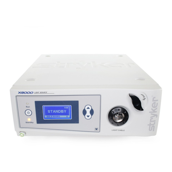
Page 8: Device Description
When operated with an ESST Bulb light cable, the X8000 senses when the scope and the light Type: 300 Watt Xenon (Elliptical) cable are separated and places the light source in Standby... -
Page 9: Device Diagrams
Device Diagrams e individual components of the X8000, which are referred to throughout this manual, are identi fi ed in the following diagrams. Top Chassis Assembly ... - Page 10 Bottom Chassis Assembly ...
-
Page 12: Basic Maintenance
Warning Do not reach inside the bulb door for e X8000 uses a Xenon bulb, which has a guaranteed any reason other than replacing the bulb life of 500 hours when used properly. Always follow these module. Touching parts other than the... -
Page 13: Replacing The Fuses
To help avoid the risk of fi re, use only 5.0A 250V fuses. Reinstall the fuse holder. Disposing of the X8000 is product is considered electronic equipment. It must not be disposed of as unsorted municipal waste and must be collected separately. -
Page 14: Troubleshooting
Mode button to switch from Standby to Run. If the unit remains in Standby: Ensure the light cable is correctly engaged with the cable port. If an ESST cable is connected to the X8000, ensure the cable is attached to the scope using an ESST scope adapter. -
Page 15: Error Code Definitions
Error Code Definitions e X8000 displays error codes when one of the following conditions occurs. Follow the recommended action to correct the error. Code Definition Recommended Action All conditions are met for the bulb to illuminate, yet it Consult the Diagnosis section of this manual. -
Page 16: Diagnosis
Diagnosis • PD2—reads 3.3 volts if the door reed switches are closed. If PD2 reads 0 volts, Check if the reed switches on the bulb To diagnose system errors, follow the strategies provided mount boards are soldered properly. If below. For steps that involve test points on the control necessary, repair the soldering. - Page 17 Measure the voltage for TP34. Make sure that the 6-pin power cable from the ballast to the control board is connected. • If TP34 reads 0 or 1.6 volts, replace the control board. (See the Repair/Replacement section of this • If the power button lights up, perform steps manual.) 1 –...
- Page 18 Brightness cannot be adjusted E-3 error appears on the LCD display Switch the light source between STANDBY and Probe TP13 with a multimeter. RUN modes by pressing on the membrane switch. • If it reads 3.3 volts, and E-3 still appears on the (Make sure to use a non-ESST cable, or an ESST display, replace the control board.
- Page 19 Shutter makes noise or does not move properly. Check the pinouts of the motor cable and the bulb mount board/control board cable. Make sure the wire colors match the drawing. Make sure the connectors J1 and J2 on the bulb mount board are not soldered in the wrong direction.
-
Page 20: Control Board Diagrams
Control Board Diagrams... -
Page 21: Repair/Replacement
For all steps that involve the application of Loctite, apply Loctite to the threaded holes rather than to the threads on the screws e X8000 Light Source is a precision instrument that has unless otherwise speci fi been engineered and manufactured with great care to ensure the safety of operators and patients. -
Page 22: Chassis Cover
Parts Unscrew Chassis Cover • Power • 6-32 x 0.25 PH from Chassis. Screwdriver Ext. Sems. (2) (Phillips) (198) • X8000 Cover Torque setting of 5. (407) • X8000 Chassis (343) Remove Chassis Cover • X8000 Cover from Chassis. (407) •... -
Page 23: Control Board
• 2-56 Hex Nut connected to the Control Driver (866) Board. Unscrew S-Bracket • S-Bracket from Chassis as shown. (585) • X8000 Chassis (343) Unscrew U-Bracket from • 4mm Nut • 2-56 Hex Nut Chassis as shown. Driver (2) (866) •... - Page 24 Get New Control Board. • X8000 Control Remove Control Board Board (873) from metal-shielded bag and place on ESD-safe Mat. Loosen the Fan Support • 5/16” Nut • 6-32 SS Nut from the Chassis. is will Driver (489) allow for easier reassembly.
- Page 25 Connect 3-Wire Fan from • 3-Wire Fan Ballast Fan to Control Cable from Board connector J10 Ballast Fan (3- (BALLAST FAN). Pin 3-Wire) • X8000 Control Board (873) Do not bend Control Board! Connect 4-Pin 4-Wire • Control Control Board/Ballast Board/Ballast...
- Page 26 • Control Control Board/Ballast Board/Ballast Cable from Ballast to Cable (6-Pin Control Board connector J6 6-Wire) (567) (DC POWER – 12V). • X8000 Control Board (873) Do not bend Control Board! Connect 8-Pin 8-Wire • Control Control Board/Bulb Mount Board/Bulb...
-
Page 27: Ballast
Tools Needed Parts Remove Chassis Cover from Chassis (procedure 1.0). Disconnect all cables on the Control Board side. • X8000 Control Board (873) Do not bend Control Board! Remove green Ground Post • Needlenose • Ground Post A/C Inlet Board/Ballast... - Page 28 Unscrew Ballast from front- • Power • 6-32 x 5/16 Chassis PEM as shown. Screwdriver PH Screw (1) (Phillips) (102) • X8000 Ballast (413) • X8000 Chassis (313) Unscrew Ballast from • Power • 6-32 x 5/16 front-right Chassis PEM as Screwdriver PH Screw (1) shown.
- Page 29 Remove Brown and Blue • Needlenose • X8000 Ballast lead of AC Inlet Board/ Pliers (413) Ballast Cable from original • A/C Inlet Ballast. Board/ Ballast Cable Assembly (571) Remove Control Board/ • X8000 Ballast Ballast Lamp Status Cable (413) from original Ballast.
- Page 30 Attach Control Board/ • X8000 Ballast Ballast Cable -567 to Ballast (413) Connector J422. • Control Board/ Ballast Cable Assembly (6-Pin 6-Wire) (567) Attach Control Board/ • X8000 Ballast Ballast Lit-Enable-Intensity (413) Cable -563 to Ballast • Control Connector J500.
- Page 31 Attach Brown lead of AC • Needlenose • X8000 Ballast Inlet Board/Ballast Cable Pliers (413) -571 to middle Ballast • A/C Inlet connector NEUT J102 on Board/ Ballast. Ballast Cable Assembly (571) Flat end of connector should face in towards Ballast.
- Page 32 Screw Ballast to front-right • Power • 6-32 x 5/16 Chassis PEM as shown. Screwdriver PH Screw (1) (Phillips) (102) • X8000 Ballast (413) • X8000 Chassis (313) Screw Ballast to front-le • Power • 6-32 x 5/16 Chassis PEM as shown.
- Page 33 Cathode Cable from rear Screwdriver Anode Cable Banana Plug to Ballast (Phillips) Assembly connector J604 LAMP – (568) • X8000 Ballast (413) Screw Cable fl at side down.Torque setting of 3! Reconnect all the cables to the Control Board (procedure 2.0, seq 120 - 170).
-
Page 34: Bulb Mount Board
Chassis (procedure 1.0). Remove the Bulb Assembly. Unplug A/C Inlet Board/Bulb Mount Board Cable from A/C Inlet Board. Unplug Stepper Motor • X8000 Stepper connector from Bulb Motor (341) Mount Board connector J2 • X8000 as shown. Also unplug A/C Horizontal... - Page 35 PEM’s above Rail Plate until • X8000 secure. Horizontal Bulb Mount Board Assembly (279) • X8000 Rail Plate (329) Plug Stepper Motor • X8000 Stepper connector into Bulb Mount Motor (341) Board connector J2 as • A/C Inlet shown. Also, plug in A/C...
- Page 36 Slide Chassis Cover onto • X8000 Cover Chassis until fl ush with (407) Chassis and secure. • X8000 Chassis (343) Screw Chassis Cover to • Power • 6-32 x 0.25 PH Chassis. Insert Bulb back Screwdriver Ext. Sems. (2) in unit.
-
Page 37: Ac Inlet Board
PH Screw (3) Remove AC Inlet board and (Phillips) (102) AC Inlet Shield from unit. • A/C Inlet Board (121) • X8000 Chassis (343) • AC Inlet Shield (014) Get new A/C Inlet Board. • A/C Inlet Remove A/C Inlet Board... - Page 38 (Phillips) (102) of Chassis. Attach AC Inlet • A/C Inlet Shield to single screw on Board (121) side of board. • X8000 Chassis (343) • AC Inlet Shield (014) Connect 3-Pin 2-Wire • A/C Inlet A/C Inlet Board/Ballast Board/Ballast...
- Page 39 Board Cable to Bulb Mount Mount Board Board connector J1. Cable (8-Pin 8-Wire) (566) • Bulb Mount Board (279) Slide Chassis Cover onto • X8000 Cover Chassis until fl ush with (407) Chassis and secure. • X8000 Chassis (343) Screw Chassis Cover to •...
-
Page 40: Jaw Handle
Make sure the Jaw (554) Handle Key remains in the Pinion Sha groove • Jaw Handle Key (641) • X8000 Pinion (298) Place small amount of • 1/16” Hex • #6 x ¼ FLPT Loctite 222 onto threaded... -
Page 41: Led Power Switch
(procedure 6.0, seq 700). Remove Jaw Handle Key • Jaw Handle from Pinion Sha groove. Key, X7000 (641) • X8000 Pinion (298) Unsnap Front Panel from • X8000 Front Chassis as shown. Panel (337) • X8000 Chassis (343) Unplug Control B oard/ •... - Page 42 Unplug 3mm LED • X8000 3mm connector from Display LED (594) Board connector as shown. • Display Board (336) Pull 3mm LED from rear of • X8000 3mm Power Button. LED (594) • Power Button (226) Get new 3mm LED. Insert •...
- Page 43 Display Board connector Board Cable J20 and pass through front Assembly of Chassis as shown. (5-Pin 5-Wire) (565) • X8000 Display Dress LED Cable under Board (336) Display Board! Snap Front Panel to Chassis • X8000 Front as shown. Panel (337) •...
- Page 44 Screw Chassis Cover to • Power • 6-32 x 0.25 PH Chassis. Screwdriver Ext. Sems. (2) (Phillips) (198) • X8000 Cover Torque setting of 5. (407) • X8000 Chassis (343)
-
Page 45: Display Board
8.0 Display Board Seq. Task Description Figure Tools Needed Parts Remove Chassis Cover from Chassis (procedure 1.0). Disconnect front panel from unit (procedure 7.0, seq 730 - 770). Unplug Front Panel Overlay • Front Panel Cable from Display Board Overlay Cable connector J20. - Page 46 Plug Beam Sensor-ESST/ • Beam Sensor- Display Board Cable into ESST/Display Display Board connector Board Cable J17 as shown. (573) • Display Board (336) Plug Front Panel Overlay • Front Panel Cable into Display Board Overlay Cable connector J20. • Display Board (336) Tuck ribbon under Display Board to protect...
-
Page 47: Front Panel Membrane
(procedure 8.0, seq 890 - 910). Unpeel the Front Panel • Front Panel Membrane from Front Membrane Panel. (292) • X8000 Front Panel (337) 1000 Pull Front Panel Membrane • Front Panel cable through Front Panel Membrane as shown. (292) •... - Page 48 • Front Panel Membrane fl ush against Membrane Front Panel until adhesive (292) backing is secure. • X8000 Front Panel (337) Check alignment before securing. Once it is on the front panel it cannot be adjusted. 1040 Reinstall Display Board and cables (procedure 8.0, seq...
-
Page 49: Shutter
10.0 Shutter Seq. Task Description Figure Tools Needed Parts 1060 Remove Chassis Cover • X8000 Bulb from Chassis (procedure Assembly 1.0). Remove Bulb (331) Assembly. 1070 Unscrew set screw from • 1/16” Hex • 6-32 x 1/8 Shutter and motor sha ... - Page 50 Chassis. Insert Bulb back Screwdriver Screwdriver Ext. Sems. (2) Ext. Sems. (2) in unit. in unit. (Phillips) (Phillips) (198) (198) • • X8000 X8000 Cover Cover (407) (407) Torque setting of 5. Torque setting of 5. • • X8000 X8000 Chassis Chassis (343)
-
Page 51: Hot Mirror
Unscrew bottom screw Unscrew bottom screw Holder (632) Holder (632) fi fi rst and then rst and then top screw. top screw. • • X8000 X8000 Motor Motor Mount (339) Mount (339) 1150 1150 Remove Hot Mirror from Remove Hot Mirror from •... - Page 52 Reinstall the Shutter (procedure 10.0, seq 1080 (procedure 10.0, seq 1080 – 1090). – 1090). 1190 1190 Slide Chassis Cover onto Slide Chassis Cover onto • • X8000 X8000 Cover Cover Chassis until Chassis until fl fl ush with ush with (407) (407) Chassis and secure.
-
Page 53: Motor
Remove Chassis Cover from Chassis (procedure 1.0). Remove the Bulb Assembly. 1220 Remove Shutter (procedure 10.0, seq 1070 - 1080). Unplug Stepper Motor • X8000 Stepper 1230 connector from Bulb Motor (341) Mount Board connector J2 • X8000 as shown. Horizontal... - Page 54 1270 Reinstall the Shutter (procedure 10.0, seq 1080 – 1090). 1280 Slide Chassis Cover onto • X8000 Cover Chassis until fl ush with (407) Chassis and secure. • X8000 Chassis (343) 1290 Screw Chassis Cover to • Power • 6-32 x 0.25 PH Chassis.
-
Page 55: Jaw Assembly
Unscrew Lower Integrating • Screwdriver • 2-56 x ¼ FH Rod Holder from Motor (Phillips) PH Screw (2) Mount. (645) • X8000 Motor Mount (339) • Lower Integrating Rod Holder (276) 1350 Unscrew Jaw Assembly • Power • 6-32 x 3/8 from front of Chassis. - Page 56 (441) • Power • Completed Screwdriver X8000 Jaw (Phillips) Torque setting of 5! Assembly • X8000 Chassis Apply enough Loctite (343) 290 so that it is visible on Chassis threads. Reinstall Hot Mirror 1380 Holder (procedure 11.0, seq 1170).
-
Page 57: Integrating Rod
Integrating Rod Holder and Screw (2) remove rod. (344) • Upper Integrating Rod Holder (277) 1440 Slide new Integrating Rod • X8000 into Lower Integrating Rod Integrating Holder and push forward Rod (314) until fl ush with end of • Lower Holder. - Page 58 Screw Upper Integrating • 5/64” Hex • 2-56 x 0.250 1460 Rod Holder to Lower Wrench Socket HD Integrating Rod Holder. Screw (2) (344) • Upper Ensure Integrating Rod Integrating fl ush with end of Lower Rod Holder Integrating Rod Holder. (277) 1470 Complete assembly of the...
-
Page 59: Ac Inlet Filter
(procedure 2.0, seq 50 – 80). Remove Ballast 1500 (procedure 3.0, seq 230 – 280). 1510 Remove Ground Post Cable • X8000 Ground from outermost single Post Cable fl ange of A/C Inlet Filter. (591) • A/C Inlet Filter (575) - Page 60 Chassis as Tightening • A/C Inlet shown. Tool Filter (575) • ¼ ” Nut Driver • X8000 Chassis (343) Attach lower nut fi rst! 1570 Attach A/C Filter/AC Inlet • A/C Filter/AC Board Cable to A/C Inlet...
- Page 61 1580 Attach Ground Post • X8000 Ground Cable to outermost single Post Cable fl ange of A/C Inlet Filter (591) by running Cable under • A/C Inlet Ballast Duct. Filter (575) Flat side of Green Cable should face out of Chassis...
-
Page 62: Ballast Fan
Nuts (3) (491) connector from control • 3-Wire Fan board and remove fan. (507) • Fan Duct (498) • X8000 Chassis (343) 1640 Place new 3-Wire Fan onto • 3-Wire Fan Ballast side onto Chassis (507) PEM’s with sticker facing •... - Page 63 • 3-Wire Fan Duct as shown. (507) • Fan Duct (498) Do not bend fan fl ange by over-tightening. • X8000 Chassis (343) Leave lower inside nut ff Use Loctite 290 on stando ff 1660 Secure Ballast Duct to • Needlenose •...
-
Page 64: Bulb Fan
• 3-Wire Fan cable from Control Board Cable from connector J9 (BULB FAN). Bulb Fan (3- Pin 3-Wire) • X8000 Control Board (873) 1710 Use a screwdriver to pop • Flathead • Nylon Snap rivets on the bulb duct free Screwdriver. - Page 65 • 3-Wire Fan Bulb side onto Chassis (507) PEM’s with sticker facing • Fan Duct out Chassis . (498) • X8000 Chassis (343) Looking from the rear of the chassis, wire should be located at 2:00. 1750 Screw nuts to 3-Wire Fan •...
- Page 66 1780 Slide Chassis Cover onto • X8000 Cover Chassis until fl ush with (407) Chassis and secure. • X8000 Chassis (343) Screw Chassis Cover to • Power • 6-32 x 0.25 PH 1790 Chassis. Insert Bulb back Screwdriver Ext. Sems. (2) in unit.
-
Page 67: Final Testing And Inspection
Power on Test Connect the X8000 to the 120 V power supply. Press the power button on and verify that the bulb does illuminate. Insert the optical fi... - Page 68 Front Panel Functional Test While the light source is turned on, the standby LED should be lit and the display should read “Standby”. ere should be a brightness display on the top right hand corner of the LED display Press the up/down brightness membrane button to increase/decrease the brightness number in the upper right hand corner.
-
Page 69: Hi-Pot/Di-Electric Breakdown Test
Hi-Pot/Di-Electric Breakdown Test Warranty Energize the Hi-Pot tester and adjust the test voltage is Stryker Endoscopy product is warranted to the to 1.8 kV. original purchaser to be free from defects in material and Plug the test xture into the back of the unit.
Need help?
Do you have a question about the X8000 and is the answer not in the manual?
Questions and answers