
Related Manuals for Epson S5U13L01P00C100


Summary of Contents for Epson S5U13L01P00C100
- Page 1 S1D13L01 Display Controller S5U13L01P00C100 Evaluation Board User Manual Document Number: XA9A-G-001-01.3 Rev. 1.3...
- Page 2 This evaluation board/kit or development tool is intended for use by an electronics engineer and is not a consumer product. The user should use it properly and in a safe manner. Seiko Epson does not assume any responsibility or liability of any kind of damage and/or fire caused by the use of it.
-
Page 3: Table Of Contents
CN3, CN4 Host Bus Interface Connector ....14 P1, P2 Connecting to the Epson S5U13U00P00C100 USB Adapter Board ..16 Chapter 5 Technical Description . - Page 4 Seiko Epson Corporation S5U13L01P00C100 Evaluation Board Rev. 1.3...
-
Page 5: Chapter 1 Introduction
The S5U13L01P00C100 evaluation board can also connect to the S5U13U00P00C100 USB Adapter board so that it can be used with a laptop or desktop computer, via USB 2.0. The S5U13L01P00C100 evaluation board can be used with many native platforms via the host connector which provides the appropriate signals to support a variety of CPUs. -
Page 6: Chapter 2 Features
• QFP 128pin S1D13L01F00A100 Display Controller • Headers for connection to the S5U13U00P00C100 USB Adapter board Note The SPI interface is not available when the S5U13L01P00C100 evaluation board is used with the S5U13U00P00C100 USB adapter board. • Headers for connection to various host interface Note These headers are not mounted. -
Page 7: Chapter 3 Installation And Configuration
Installation and Configuration Chapter 3 Installation and Configuration The S5U13L01P00C100 evaluation board incorporates a DIP switch, jumpers, and 0 ohm resistors which allow it to be used with a variety of different configurations. 3.1 CNF[2:0] Configuration The S1D13L01 has 3 configuration inputs CNF[2:0], which are used to configure the S1D13L01 host interface type through DIP switch SW1. -
Page 8: Configuration Switches
Installation and Configuration 3.2 Configuration Switches The S5U13L01P00C100 evaluation board includes the following switch blocks which control the functions described in Table 3-2: “Switch Settings”. For jumper locations on the evaluation board, see Figure 3-1: “Configu- ration Switch and Jumper Locations (Red)” on page 10. -
Page 9: Configuration Jumpers
Installation and Configuration 3.3 Configuration Jumpers The S5U13L01P00C100 evaluation board includes the following 2-pin, 3-pin, 5-pin and 8-pin jumper blocks which control the functions described in Table 3-3: “2-Pin Jumper Settings”, Table 3-4: “3-Pin Jumper Settings”, Table 3-5: “5-Pin Jumper Settings” and Table 3-6: “8-PinJumper Setting”. For jumper locations on the evaluation board, see Figure 3-1: “Configuration Switch and Jumper Locations (Red)”... - Page 10 In connect case, Vout = 40mA (add connect Position 3-4) In connect case, Vout = 60mA (add connect Position3-4 and Position 7-8 No Jumper Position5-6) = suggested settings Figure 3-1: Configuration Switch and Jumper Locations (Red) Seiko Epson Corporation S5U13L01P00C100 Evaluation Board Rev. 1.3...
-
Page 11: Zero Ohm Resistor Configuration
Connector CN4 is only land. 3.5.2 3.3V The S5U13L01P00C100 evaluation board is designed to generate 3.3V for on board OSC from 5V via the S5U13U00P00C100 USB adapter board or connector CN4. 5V must be supplied from the S5U13U00P00C100 or CN4. The 3.3V power supply is fixed output. See Table 3-7: “S5U13L01P00C100 Power Mapping” for detail. - Page 12 Installation and Configuration Table 3-7: S5U13L01P00C100 Power Mapping Name Purpose Adj. Range COREVDD S1D13L01 COREVDD 1.5V Fixed — 1.5V PLLVDD S1D13L01 PLLVDD 1.5V Fixed IOVDD\ S1D13L01 IOVDD 1.8/3.3V Typical 1.5~3.8V 3.3V SG-210 VDD 3.3V Fixed — 3.3V LED+ Backlight for panel, 38V/60mA max...
-
Page 13: Led Status Indicators
Installation and Configuration 3.6 LED Status Indicators The S5U13L01P00C100 evaluation board has 3 LED status indicators which provide a quick visual status of the following conditions as described in Table 3-8: “LED Status Indicators”. Note Connector CN4 is only land. -
Page 14: Chapter 4 Connectors
4.2 CN3, CN4 Host Bus Interface Connector All S1D13L01 host interface pins are available on connectors CN3 and CN4. This allows the S5U13L01P00C100 evaluation board to be connected to a variety of development platforms. For S1D13L01 host interface pin mapping, see Table 3-1: “Host Interface Pin Mapping,”... - Page 15 Connectors Figure 4-1: Host and Panel Bus Connector Location (CN1, CN2, CN3, CN4, CN5) Seiko Epson Corporation S5U13L01P00C100 Evaluation Board Rev. 1.3...
-
Page 16: P1, P2 Connecting To The Epson S5U13U00P00C100 Usb Adapter Board
When the S5U13L01P00C100 is connected to the S5U13U00P00C100 USB Adapter board, there are 2 LEDs on the S5U13L01P00C100 which provide a quick visual status of the USB adapter. HB (D300) blinks to indicate that the USB adapter board is active. ENUM (D301) turns on to indicate that the USB has been enumerated by the PC. - Page 17 For the pinout of connectors P1 and P2, see Section Chapter 7, “Schematic Diagrams” on page 23. Note A windows driver must be installed on the PC when the S5U13L01P00C100 is used with the S5U13U00P00C100 USB Adapter Board. The S1D13xxxUSB driver is available at vdc.epson.com.
-
Page 18: Chapter 5 Technical Description
Attaching an ammeter while doing other tests can cause a voltage drop across the ammeter and may produce in- valid test results. 5.2 Oscillator Support for CLKI input The S5U13L01P00C100 evaluation board has an on-board 24MHz oscillator (Y1) which drives the input for the S1D13L01 CLKI pin. Seiko Epson Corporation S5U13L01P00C100 Evaluation Board Rev. -
Page 19: Hardware Reset
Technical Description 5.3 Hardware Reset The S5U13L01P00C100 evaluation board has an on-board reset IC which drives the RESET# input pin on the S1D13L01. This occurs when push button SW4 is pressed. Figure 5-1: Reset Switch (SW4) Location Seiko Epson Corporation S5U13L01P00C100 Evaluation Board Rev. -
Page 20: Chapter 6 Parts List
Parts List Chapter 6 Parts List Table 6-1 : S5U13L01P00C100 Parts List Manufacture Part No. / Item Reference Part Description Comments LCD Controller QFP15-128 0.5mm S1D13L01 EPSON S1D13L01F Pitch TPS73615DRB Single Channel LDO Fixed TI TPS73615DRB TPS73633DRB Single Channel LDO Fixed... - Page 21 Parts List Table 6-1 : S5U13L01P00C100 Parts List Manufacture Part No. / Item Reference Part Description Comments R300, R301, R302, R303, R304, R305, R306, R307, R308, R309, R310, R311, R312, R314, R315, R316, R317, R318, R319, R320, R321, R322, R323, R324,...
- Page 22 Parts List Table 6-1 : S5U13L01P00C100 Parts List Manufacture Part No. / Item Reference Part Description Comments D303 CRS04 TOSHIBA FERRITE CHIP 220 OHM 2000mA L101, L102 BLM21P MURATA BLM21P 0805 SG-210SCB 24MHz CRYSTAL OSCILLATOR 24MHz EPSON SG-210SCB 24MHz Box Connector 2.54mm 40pin not mounted Pin Header 2.54mm 16pin...
-
Page 23: Chapter 7 Schematic Diagrams
Schematic Diagrams Chapter 7 Schematic Diagrams Figure 7-1: S5U13L01P00C100 Schematics (1 of 5) Seiko Epson Corporation S5U13L01P00C100 Evaluation Board Rev. 1.3... - Page 24 Schematic Diagrams Figure 7-2: S5U13L01P00C100 Schematics (2 of 5) Seiko Epson Corporation S5U13L01P00C100 Evaluation Board Rev. 1.3...
- Page 25 Schematic Diagrams Figure 7-3: S5U13L01P00C100 Schematics (3 of 5) Seiko Epson Corporation S5U13L01P00C100 Evaluation Board Rev. 1.3...
- Page 26 Schematic Diagrams Figure 7-4: S5U13L01P00C100 Schematics (4 of 5) Seiko Epson Corporation S5U13L01P00C100 Evaluation Board Rev. 1.3...
- Page 27 Schematic Diagrams Figure 7-5: S5U13L01P00C100 Schematics (5 of 5) Seiko Epson Corporation S5U13L01P00C100 Evaluation Board Rev. 1.3...
-
Page 28: Chapter 8 Board Layout
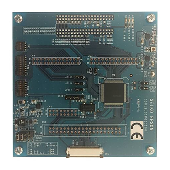
Board Layout Chapter 8 Board Layout Figure 8-1: S5U13L01P00C100 Board Layout - Top View Seiko Epson Corporation S5U13L01P00C100 Evaluation Board Rev. 1.3... - Page 29 Board Layout Figure 8-2: S5U13L01P00C100 Board Layout - Bottom View Seiko Epson Corporation S5U13L01P00C100 Evaluation Board Rev. 1.3...
-
Page 30: Chapter 9 Change Record
Change Record Chapter 9 Change Record XA9A-G-001 Rev. 1.3 issued April 09, 2018 • Updated address/contact page • Updated Epson web page and email address • Minor formatting changes XA9A-G-001 Rev. 1.2 issued December 5, 2014 • Corrected cropped board schematics. -
Page 31: Chapter 10 Sales And Technical Support
Sales and Technical Support Chapter 10 Sales and Technical Support For more information on Epson Display Controllers, visit the Epson Global website. https://global.epson.com/products_and_drivers/semicon/products/display_controllers/ For Sales and Technical Support, contact the Epson representative for your region. https://global.epson.com/products_and_drivers/semicon/information/support.html Seiko Epson Corporation S5U13L01P00C100 Evaluation Board...
Need help?
Do you have a question about the S5U13L01P00C100 and is the answer not in the manual?
Questions and answers