
Related Manuals for Epson S5U13L01P00C100


Summary of Contents for Epson S5U13L01P00C100
- Page 1 S1D13L01 Display Controller S5U13L01P00C100 Evaluation Board User Manual SEIKO EPSON CORPORATION Rev. 1.0 Arrow.com. Downloaded from...
- Page 2 No part of this material may be reproduced or duplicated in any form or by any means without the written permission of Seiko Epson. Seiko Epson reserves the right to make changes to this material without notice. Seiko Epson does not assume any lia-...
-
Page 3: Table Of Contents
CN3, CN4 Host Bus Interface Connector ....14 P1, P2 Connecting to the Epson S5U13U00P00C100 USB Adapter Board ..15 Chapter 5 Technical Description . - Page 4 EPSON S5U13L01P00C100 Evaluation Board User Manual (Rev. 1.0) Arrow.com. Arrow.com. Arrow.com. Arrow.com. Downloaded from Downloaded from Downloaded from Downloaded from...
-
Page 5: Chapter 1 Introduction
The S5U13L01P00C100 evaluation board can also connect to the S5U13U00P00C100 USB Adapter board so that it can be used with a laptop or desktop computer, via USB 2.0. The S5U13L01P00C100 evaluation board can be used with many native platforms via the host connector which provides the appropriate signals to support a variety of CPUs. -
Page 6: Chapter 2 Features
• QFP 128pin S1D13L01F00A100 Display Controller • Headers for connection to the S5U13U00P00C100 USB Adapter board Note The SPI interface is not available when the S5U13L01P00C100 evaluation board is used with the S5U13U00P00C100 USB adapter board. • Headers for connection to various host interface Note These headers are not mounted. -
Page 7: Chapter 3 Installation And Configuration
Chapter 3 Installation and Configuration Chapter 3 Installation and Configuration The S5U13L01P00C100 evaluation board incorporates a DIP switch, jumpers, and 0 ohm resistors which allow it to be used with a variety of different configurations. 3.1 CNF[2:0] Configuration The S1D13L01 has 3 configuration inputs CNF[2:0], which are used to configure the S1D13L01 host interface type through DIP switch SW1. -
Page 8: Configuration Switches
Chapter 3 Installation and Configuration 3.2 Configuration Switches The S5U13L01P00C100 evaluation board includes the following switch blocks which control the functions described in Table 3-2: “Switch Settings”. For jumper locations on the evaluation board, see Figure 3-1: “Configu- ration Switch and Jumper Locations (Red)” on page 10. -
Page 9: Configuration Jumpers
Chapter 3 Installation and Configuration 3.3 Configuration Jumpers The S5U13L01P00C100 evaluation board includes the following 2-pin, 3-pin, 5-pin and 8-pin jumper blocks which control the functions described in Table 3-3: “2-Pin Jumper Settings”, Table 3-4: “3-Pin Jumper Settings” , Table 3-5: “5-Pin Jumper Settings”... - Page 10 In connect case, Vout = 60mA (add connect Position3-4 and Position 7-8 No Jumper Position5-6) = suggested settings Figure 3-1: Configuration Switch and Jumper Locations (Red) EPSON S5U13L01P00C100 Evaluation Board User Manual (Rev. 1.0) Arrow.com. Arrow.com. Arrow.com. Arrow.com. Arrow.com. Arrow.com.
-
Page 11: Zero Ohm Resistor Configuration
Connector CN4 is not mounted. Space is allocated on the board for mounting. 3.5.2 3.3V The S5U13L01P00C100 evaluation board is designed to generate 3.3V for on board OSC from 5V via the S5U13U00P00C100 USB adapter board or connector CN4. 5V must be supplied from the S5U13U00P00C100 or CN4. - Page 12 1.5~3.8V 3.3V SG-210 VDD 3.3V Fixed — 3.3V LED+ Backlight for panel, 38V/60mA max JP503 12~38V Figure 3-2: Voltage Adjustment Locations (Red) EPSON S5U13L01P00C100 Evaluation Board User Manual (Rev. 1.0) Arrow.com. Arrow.com. Arrow.com. Arrow.com. Arrow.com. Arrow.com. Arrow.com. Arrow.com. Arrow.com. Arrow.com.
-
Page 13: Led Status Indicators
Chapter 3 Installation and Configuration 3.6 LED Status Indicators The S5U13L01P00C100 evaluation board has 3 LED status indicators which provide a quick visual status of the following conditions as described in Table 3-8: “LED Status Indicators”. Note Connector CN4 is not mounted. Space is allocated on the board for mounting. -
Page 14: Chapter 4 Connectors
4.2 CN3, CN4 Host Bus Interface Connector All S1D13L01 host interface pins are available on connectors CN3 and CN4. This allows the S5U13L01P00C100 evaluation board to be connected to a variety of development platforms. For S1D13L01 host interface pin mapping, see Table 3-1: “Host Interface Pin Mapping,”... -
Page 15: P1, P2 Connecting To The Epson S5U13U00P00C100 Usb Adapter Board
4.3 P1, P2 Connecting to the Epson S5U13U00P00C100 USB Adapter Board The S5U13L01P00C100 evaluation board is designed to connect to a S5U13U00P00C100 USB Adapter Board. The USB adapter board provides a simple connection to any computer via a USB 2.0 connection. The S5U13L01P00C100 directly connects to the USB adapter board through connectors P1 and P2. - Page 16 When the S5U13L01P00C100 is connected to the S5U13U00P00C100 USB Adapter board, there are 2 LEDs on the S5U13L01P00C100 which provide a quick visual status of the USB adapter. HB (D300) blinks to indicate that the USB adapter board is active. ENUM (D301) turns on to indicate that the USB has been enumerated by the PC.
-
Page 17: Chapter 5 Technical Description
Attaching an ammeter while doing other tests can cause a voltage drop across the ammeter and may produce in- valid test results. 5.2 Oscillator Support for CLKI input The S5U13L01P00C100 evaluation board has an on-board 24MHz oscillator (Y1) which drives the input for the S1D13L01 CLKI pin. S5U13L01P00C100 Evaluation Board User Manual (Rev. 1.0) EPSON Arrow.com. -
Page 18: Hardware Reset
Chapter 5 Technical Description 5.3 Hardware Reset The S5U13L01P00C100 evaluation board has an on-board reset IC which drives the RESET# input pin on the S1D13L01. This occurs when push button SW4 is pressed. Figure 5-1: Reset Switch (SW4) Location EPSON S5U13L01P00C100 Evaluation Board User Manual (Rev. -
Page 19: Chapter 6 Parts List
C506, C509 C122, C401, GRM21BB31C106KE C403, C406, cap 10u 16v 2012 MURATA C408, C411, C413 C508 cap 0.22u/50V C510 cap 1.0u/50V S5U13L01P00C100 Evaluation Board User Manual (Rev. 1.0) EPSON Arrow.com. Arrow.com. Arrow.com. Arrow.com. Arrow.com. Arrow.com. Arrow.com. Arrow.com. Arrow.com. Arrow.com. Arrow.com. - Page 20 10 R513 res 10k SMD Trimming Potentiometer ST32ETA204 COPAL ST32ETA204CT-ND 200k D300, D301, D302 SML-310VTT86 LED red 1608 ROHM SML-310VT EPSON S5U13L01P00C100 Evaluation Board User Manual (Rev. 1.0) Arrow.com. Arrow.com. Arrow.com. Arrow.com. Arrow.com. Arrow.com. Arrow.com. Arrow.com. Arrow.com. Arrow.com. Arrow.com.
- Page 21 SPN02SYBN-RC .079 in. Jumper Shunt SULLINS SH108, SH109, SH503, SH504, SH505, SH506 EP-6 Spacer M3x6mm MAC8 3M-5 Screw M3x5mm MAC8 S5U13L01P00C100 Evaluation Board User Manual (Rev. 1.0) EPSON Arrow.com. Arrow.com. Arrow.com. Arrow.com. Arrow.com. Arrow.com. Arrow.com. Arrow.com. Arrow.com. Arrow.com. Arrow.com. Arrow.com.
-
Page 22: Chapter 7 Schematic Diagrams
Chapter 7 Schematic Diagrams Chapter 7 Schematic Diagrams Figure 7-1: S5U13L01P00C100 Schematics (1 of 5) EPSON S5U13L01P00C100 Evaluation Board User Manual (Rev. 1.0) Arrow.com. Arrow.com. Arrow.com. Arrow.com. Arrow.com. Arrow.com. Arrow.com. Arrow.com. Arrow.com. Arrow.com. Arrow.com. Arrow.com. Arrow.com. Arrow.com. Arrow.com. Arrow.com. Arrow.com. - Page 23 Chapter 7 Schematic Diagrams Figure 7-2: S5U13L01P00C100 Schematics (2 of 5) S5U13L01P00C100 Evaluation Board User Manual (Rev. 1.0) EPSON Arrow.com. Arrow.com. Arrow.com. Arrow.com. Arrow.com. Arrow.com. Arrow.com. Arrow.com. Arrow.com. Arrow.com. Arrow.com. Arrow.com. Arrow.com. Arrow.com. Arrow.com. Arrow.com. Arrow.com. Arrow.com. Arrow.com. Arrow.com. Arrow.com.
- Page 24 Chapter 7 Schematic Diagrams Figure 7-3: S5U13L01P00C100 Schematics (3 of 5) EPSON S5U13L01P00C100 Evaluation Board User Manual (Rev. 1.0) Arrow.com. Arrow.com. Arrow.com. Arrow.com. Arrow.com. Arrow.com. Arrow.com. Arrow.com. Arrow.com. Arrow.com. Arrow.com. Arrow.com. Arrow.com. Arrow.com. Arrow.com. Arrow.com. Arrow.com. Arrow.com. Arrow.com. Arrow.com. Arrow.com.
- Page 25 Chapter 7 Schematic Diagrams Figure 7-4: S5U13L01P00C100 Schematics (4 of 5) S5U13L01P00C100 Evaluation Board User Manual (Rev. 1.0) EPSON Arrow.com. Arrow.com. Arrow.com. Arrow.com. Arrow.com. Arrow.com. Arrow.com. Arrow.com. Arrow.com. Arrow.com. Arrow.com. Arrow.com. Arrow.com. Arrow.com. Arrow.com. Arrow.com. Arrow.com. Arrow.com. Arrow.com. Arrow.com. Arrow.com.
- Page 26 Chapter 7 Schematic Diagrams Figure 7-5: S5U13L01P00C100 Schematics (5 of 5) EPSON S5U13L01P00C100 Evaluation Board User Manual (Rev. 1.0) Arrow.com. Arrow.com. Arrow.com. Arrow.com. Arrow.com. Arrow.com. Arrow.com. Arrow.com. Arrow.com. Arrow.com. Arrow.com. Arrow.com. Arrow.com. Arrow.com. Arrow.com. Arrow.com. Arrow.com. Arrow.com. Arrow.com. Arrow.com. Arrow.com.
-
Page 27: Chapter 8 Board Layout
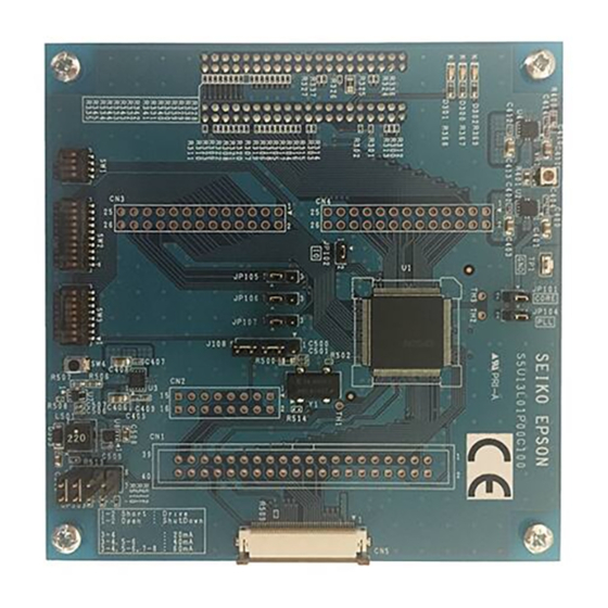
Chapter 8 Board Layout Chapter 8 Board Layout Figure 8-1: S5U13L01P00C100 Board Layout - Top View S5U13L01P00C100 Evaluation Board User Manual (Rev. 1.0) EPSON Arrow.com. Arrow.com. Arrow.com. Arrow.com. Arrow.com. Arrow.com. Arrow.com. Arrow.com. Arrow.com. Arrow.com. Arrow.com. Arrow.com. Arrow.com. Arrow.com. Arrow.com. Arrow.com. - Page 28 Chapter 8 Board Layout Figure 8-2: S5U13L01P00C100 Board Layout - Bottom View EPSON S5U13L01P00C100 Evaluation Board User Manual (Rev. 1.0) Arrow.com. Arrow.com. Arrow.com. Arrow.com. Arrow.com. Arrow.com. Arrow.com. Arrow.com. Arrow.com. Arrow.com. Arrow.com. Arrow.com. Arrow.com. Arrow.com. Arrow.com. Arrow.com. Arrow.com. Arrow.com. Arrow.com. Arrow.com.
-
Page 29: Chapter 9 References
Chapter 9 References Chapter 9 References 9.1 Documents • Epson Electronics America, Inc., S1D13L01 Hardware Functional Specification, document number XA94A001. 9.2 Document Sources • Epson Electronics America Website: http://vdc.epson.com. S5U13L01P00C100 Evaluation Board User Manual (Rev. 1.0) EPSON Arrow.com. Arrow.com. Arrow.com. - Page 30 Chapter 9 References Change Record EPSON S5U13L01P00C100 Evaluation Board User Manual (Rev. 1.0) Arrow.com. Arrow.com. Arrow.com. Arrow.com. Arrow.com. Arrow.com. Arrow.com. Arrow.com. Arrow.com. Arrow.com. Arrow.com. Arrow.com. Arrow.com. Arrow.com. Arrow.com. Arrow.com. Arrow.com. Arrow.com. Arrow.com. Arrow.com. Arrow.com. Arrow.com. Arrow.com. Arrow.com. Arrow.com. Arrow.com. Arrow.com.
- Page 31 20/F, Harbour Centre, 25 Harbour Road Wanchai, Hong Kong Phone: +852-2585-4600 FAX: +852-2827-4346 Telex: 65542 EPSCO HX EPSON TAIWAN TECHNOLOGY & TRADING LTD. 14F, No. 7, Song Ren Road, Taipei 110, TAIWAN Phone: +886-2-8786-6688 FAX: +886-2-8786-6660 EPSON SINGAPORE PTE., LTD.
Need help?
Do you have a question about the S5U13L01P00C100 and is the answer not in the manual?
Questions and answers