Yetter 5000 Series Owner's Manual
Hide thumbs
Also See for 5000 Series:
- Owner's manual (48 pages) ,
- Owner's manual & parts list (32 pages) ,
- Operator's manual (24 pages)
Table of Contents
Advertisement
Quick Links
CHOPPING / 20" & 30" ROWS
CASE – IH / NEW HOLLAND CORN HEADS
YETTER MANUFACTURING CO.
Founded 1930
Colchester, IL 62326
Toll free: (800)447-5777.
Fax: (309)776-3222
Website: yetterco.com
E-mail: info@yetterco.com
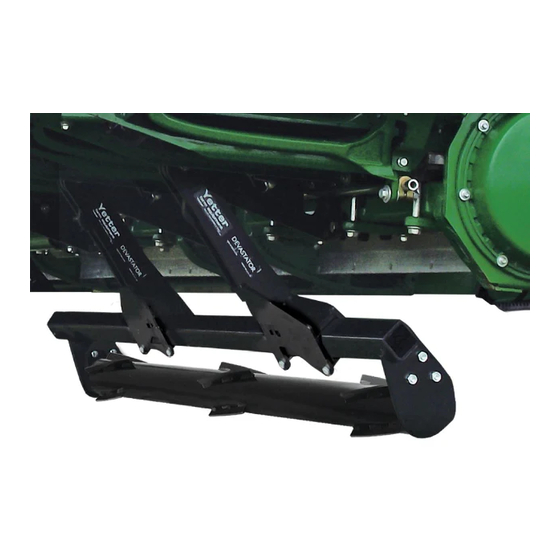
5000 SERIES
STALK DEVASTATOR
OWNER'S MANUAL
PART IDENTIFICATION
2565-970_REV_B ● 8/2022
Advertisement
Table of Contents

Related Manuals for Yetter 5000 Series


Summary of Contents for Yetter 5000 Series
- Page 1 5000 SERIES STALK DEVASTATOR CHOPPING / 20” & 30” ROWS CASE – IH / NEW HOLLAND CORN HEADS OWNER’S MANUAL PART IDENTIFICATION 2565-970_REV_B ● 8/2022 YETTER MANUFACTURING CO. Founded 1930 Colchester, IL 62326 Toll free: (800)447-5777. Fax: (309)776-3222 Website: yetterco.com...
-
Page 2: Table Of Contents
WARRANTY Yetter Manufacturing warrants all products manufactured & sold by it against defects in material. This warranty being expressly limited to replacement at the factory of such parts or products as shall appear to be defective after inspection. -
Page 3: Safety Information
BE ALERT! YOUR SAFETY IS INVOLVED WATCH FOR THIS SYMBOL. IT POINTS OUT IMPORTANT SAFETY PRECAUTIONS. IT MEANS “ATTENTION – BE ALERT!” It is your responsibility as an owner, operator, or supervision to know and instruct everyone using this machine at the time of initial assignment and at least annually thereafter, of the proper operation, precautions, and work hazards which exist in the operation of the machine in accordance with OSHA regulations. - Page 4 PLEASE READ, VERY IMPORTANT SECURE CORN HEADER AGAINST UNWANTED LOWERING BY APPLYING THE LOCKING MECHANISM ON THE HYDRAULIC CYLINDERS! 1. Attach head to combine, lock head to combine 2. Raise the head off the ground and engage safety stop on the feeder house cylinder.
-
Page 5: Operation Checklist / Torque
DEVASTATOR OPERATION CHECKLIST Please fill this out after the Yetter Stalk Devastator has been installed. DATE____/____/____ YETTER KIT # - 5000-____ CORN HEAD MAKE/MODEL___________________ COMBINE MAKE/MODEL__________________ FRONT TIRE SIZE______________ REAR TIRE SIZE______________ REAR AXLE POSITION______________ SNAPPING ROLLS USING______________ CHOPPING BLADES YES / NO DECK PLATE ANGLE_____°... -
Page 6: Bill Of Materials / Tools Needed / Pictorial Part List
BILL OF MATERIALS PER KIT 5000-060C – 6R30 Case 2606/4206/4406 & New Holland 99C/980R Chopping Rigid Corn Heads – 2) 5000-160A Roller Bearing Bolt Bag, 4) 5000-173 Torsion Mount Bolt Bag, 1) 5000-175 Manual Bag, 4) 5000-187 Locking Torsion Assembly, 2) 5000-272 3R30 Roller W.A., 2) 5000-275A 4R20/3R30 Roller Mount W.A., 4) 5000-294A Torsion Arm W.A. -
Page 7: Assembly Instructions
ASSEMBLY INSTRUCTIONS BELOW ARE RECOMMENDED LOCATIONS OF THE TORSION PIVOT ASSEMBLY, ALTERNATE LOCATIONS MAY BE USED IF INTERFERENCE OCCURS! 5000-060 6 ROW 30” Arrows indicate 5000-187 Torsion Pivot locations 5000-061 8 ROW 30” Arrows indicate 5000-167 Torsion Pivot locations... - Page 8 ASSEMBLY INSTRUCTIONS BELOW ARE RECOMMENDED LOCATIONS OF THE TORSION PIVOT ASSEMBLY, ALTERNATE LOCATIONS MAY BE USED IF INTERFERENCE OCCURS! 5000-062 12 ROW 30” Arrows indicate 5000-187 Torsion Pivot locations 5000-063 12 ROW 20” Arrows indicate 5000-187 Torsion Pivot locations...
- Page 9 ASSEMBLY INSTRUCTIONS Step 1: Attach each 5000-187 locking torsion assembly to the frame using 2) 5/8 X 4 X 5 ½ U-Bolts & 4) 5/8 – 11 Hex Flange Nuts. See pages 7 – 8 for each locking torsion pivot assembly mounting location for your corn head. On some corn head models, the locking torsion assembly will have to go between the gearbox mounting straps.
- Page 10 ASSEMBLY INSTRUCTIONS Attach the roller mount to pivot arms using ½” x 2-1/2” x 3-1/2” U-bolts & lock nuts. See diagrams on pages 7 – 8 to Step 3: determine orientation of roller & roller mount tube locations for your corn head. DO NOT TIGHTEN HARDWARE YET!! NOTE: The bearing support tab on the roller mount tube should be on the backside of the bearing mount plate.
- Page 11 ASSEMBLY INSTRUCTIONS Step 5: Slide roller mount tubes to align the row center with the traction bars. Fully tighten hardware from Step 3. In some circumstances, the traction bar may have to be off-center of the row some. REAR VIEW Step 6: (If Applicable) On chopping corn heads, trim 3 inches off the bottom of the back curtain to keep the roller from contacting the curtain.
-
Page 12: Lock Up / Operation
LOCK UP To “lock up” Devastator rollers, lower head down & rotate the locking handle 90 degrees. If the handle is vertical, the devastator will be in operation mode. If the handle is horizontal & is in front of the pivot arm (see yellow circle below), the devastator is locked up. On torsion style devastators without the lock up feature, a 5000-430 Lock Pin can be ordered separately to lock up devastator rollers. -
Page 13: Storage / Transport / Bearing Replacement
STORAGE/TRANSPORT Head cart may need adjusted to fit the head with devastator correctly. E.g. raising or fore/aft adjustment of saddles/top rail on the head cart. If head cart does not have these adjustments, adding a tube extension to top rail or adding extension to saddle/corn head may be required. Side to side tilt may need used to clear taller head cart tires or locking the devastator up. -
Page 14: Part Identification
5000-060C PART IDENTIFICATIONS CASE 4406 6R30 DEVASTATOR ITEM PART # DESCRIPTION QUANTITY 2502-353 ½ - 13 X 2 ½ HHCS GR 8 ZP 2502-430 ¾ - 10 X 8 HHCS GR 8 ZP 2520-357 1/2-13 LOCK HEX NUT, GR A, ZP 5/8 –... - Page 15 5000-061C PART IDENTIFICATIONS CASE 4408 8R30 DEVASTATOR ITEM PART # DESCRIPTION 2502-353 ½ - 13 X 2 ½ HHCS GR 8 ZP 2502-430 ¾ - 10 X 8 HHCS GR 8 ZP 2520-357 1/2-13 LOCK HEX NUT, GR A, ZP 5/8 –...
- Page 16 5000-062C PART IDENTIFICATION CASE 4412 12R30 DEVASTATOR FRONT VIEW ITEM PART # DESCRIPTION 2502-353 ½ - 13 X 2 ½ HHCS GR 8 ZP 2502-430 ¾ - 10 X 8 HHCS GR 8 ZP 2520-357 1/2-13 LOCK HEX NUT, GR A, ZP 5/8 –...
- Page 17 5000-063C PART IDENTIFICATION CASE 4412 12R20 DEVASTATOR ITEM PART # DESCRIPTION 2502-353 ½ - 13 X 2 ½ HHCS GR 8 ZP 2502-430 ¾ - 10 X 8 HHCS GR 8 ZP 2520-357 1/2-13 LOCK HEX NUT, GR A, ZP 5/8 –...
-
Page 18: Troubleshooting
TROUBLESHOOTING ISSUE CAUSE CORRECTIVE ACTION 1. Adjust head angle to 22 – 25 degrees (see page 12) Residue Plugging 1. Incorrect Head Angle 2. Roller Mount Tube 2. Make sure the Bearing Support Tab is on the backside incorrectly installed of the Roller Mount Tube 3. - Page 21 2565-970_REV_B ● 08/2022...
Need help?
Do you have a question about the 5000 Series and is the answer not in the manual?
Questions and answers