Table of Contents
Advertisement
Advertisement
Table of Contents
Troubleshooting

Related Manuals for Saswell SAS900STK-2


Summary of Contents for Saswell SAS900STK-2
- Page 1 SAS900STK-2 OPERATING INSTRUCTION...
- Page 2 SAS900STK-2 SINGLE STAGE PROGRAMMABLE THERMOSTAT 1 Heat / 1 Cool single stage thermostat. 5+2 Programmable, Compatible with heat pump system Installation and Operation Manual Specification:-------------------------------------------------------------------------------- Power Supply: 20VAC-30VAC 50-60HZ or Battery powered. Terminal Load: 1.0A per terminal, 3.0A maximum total load Set Point Temperature Range: 45ºF to 90ºF (7ºC to 32ºC).
- Page 3 Large LCD display with backlight, continuous backlight option Simultaneous heat and cool set point storage Display of room temperature, set temperature and current time simultaneously Fan switch with ON and AUTO Permanent user setting retention during power loss. No batteries are required. ...
- Page 4 Intelligent Recovery Option for optimizing comfort IMPORTANT SAFETY INFORMATION------------------------------------------- Always turn off power at the main power source by removing the fuse, or switching the circuit breaker to the off position before installing, removing, cleaning, or servicing this thermostat. ...
- Page 5 control to test installation. This will damage the thermostat and void the warranty. Do not switch the system to cool if the temperature is below 50ºF (10ºC). This can damage the air conditioning system and may cause personal injury. Replace batteries when the battery icon indicates the low battery message.
- Page 6 Turn off power to the heating and cooling system by removing the fuse or switching the appropriate circuit breaker off. Remove the cover of the old thermostat. This should expose the wires. Label the existing wires from the existing thermostat before removing. After labeling the wires, remove the wires from the wire terminals.
- Page 7 INSTALL THE THERMOSTAT---------------------------------------------------------------------------- ATTACH THERMOSTAT BASE TO WALL PULL THE COVER OFF THE BASE. WARNING!: Electrical Shock Hazard Turn off power at the main service panel by removing the fuse or switching the appropriate circuit breaker to the OFF position before removing the existing thermostat. Turn off power to the heating and cooling system by removing the fuse or switching the appropriate circuit breaker off.
- Page 8 Place the system switch (COOL/OFF/HEAT) in the OFF position. Place the FAN (AUTO/ON) switch in the AUTO position. Gently pull the cover straight off the base. (See figure 2.) Put the thermostat base against the wall where you plan to mount it. (Be sure the wires will feed through the wire opening in the base of the thermostat.) Mark the placement of the mounting holes.
- Page 9 Insert stripped, labeled wires into matching wire terminals. See “Wiring Diagrams”, Section 3, Figure 3. CAUTION: Be sure exposed portions of wires do not touch other wires. Tighten screws on terminal block. Gently tug on each wire to be sure of proper connection.
- Page 10 Replace the cover on the thermostat by snapping it in place. Turn on power to the system at the main service panel. Test thermostat operation as described in the following section. FAN OPTION SWITCH Read the following information before setting the fan option switch (See figure 1). If you are unsure of your application, contact a qualified service person.
- Page 11 BATTERY OPERATION The thermostat will operate from 2 size “AAA” alkaline batteries or 24VAC power. When operated from batteries, connection to the “C” (common) or (neutral) terminal is not required. NOTE: When operated from batteries (No “C” terminal connection), the LCD display backlight options are limited to option 1 (disabled) or option 2 (30 second illumination after each button press).
- Page 13 CHECK THERMOSTAT OPERATION------------------------------------------------------------------ If at any time during testing your system does not operate properly, contact a qualified service person. Turn on power to the system. Fan Operation Move the system switch to the OFF position. If your system does not have a “G” (Fan) terminal connection, skip to the Heating System.
- Page 14 When the (FA)st heating cycle rate is selected in the configuration menu, (see configuration menu item 2), the thermostat will call for heat at 0.5ºF (0.5ºC) below set-point, and turn off at set point. When the (SL)ow heating cycle rate is selected, the thermostat will call for heat at 1.5ºF (1.5ºC) below set-point, and turn off at set-point.
- Page 15 When the (FA)st cooling cycle rate is selected in the configuration menu, (see configuration menu item 2), the thermostat will call for cooling at 0.5ºF (0.5ºC) above set-point, and turn off set point. When the (SL)ow cool cycle rate is selected, the thermostat will call for cooling at 1.5ºF (1.5ºC) above set-point, and turn off at set-point.
- Page 16 Replacing Batteries If your thermostat was pre-installed, the batteries may be in place. If the battery icon on the display is flashing, it indicates that the batteries need to be replaced. When the thermostat is powered only by battery, the battery icon will flash for approximately 2 months before the batteries are expected to expire.
- Page 17 Gently pull the cover straight off the base. Install two “AAA” alkaline batteries in the battery compartment. Be sure to match the positive (+) ends of the batteries with the positive terminals marked in the battery compartment. It may take as long as 30 seconds for the Low Battery Icon to Disappear after changing batteries.
- Page 18 The configuration menu allows you to set certain thermostat operating characteristics to your system or personal requirements. Move the SYSTEM switch to the OFF position, then press and hold the PRGM and RUN buttons for 3 seconds to enter the configuration menu. The display will show the first item in the configuration menu.
- Page 20 Select cooling cycle rate The FA setting is used to produce shorter cooling cycles. The SL setting produces a longer cooling cycle. Both settings produce very accurate temperature control and can be set to your personal preference. FA cycles the system at a 0.5ºF (0.5ºC) differential, and SL cycles the system at 1.5ºF (1.5ºC).
- Page 21 Select system heating type Users can select the system heating type according to their heating system. Select 0 for gas, oil, or electric heating systems. Select 1 for a heat pump heating system. Select display backlight The display backlight improves display contrast in low lighting conditions.
- Page 22 second illumination after each button press). Select filter replacement run time The thermostat will display the Filter Alarm after a set time of operation. This is a reminder to change or clean your air filter. This time can be set from 0 to 12 months in 1 month increments.
- Page 23 higher or lower. Your thermostat can be accurately calibrated to match your previous thermostat. The current or adjusted room temperature will be displayed on the display. Select compressor lockout delay To protect the compressor from short cycling, you can select compressor off-time cycle between 0 or 5 minutes.
- Page 24 room temperature is at set-point at the set-up time. THERMOSTAT OPERATION Setting the thermostat This thermostat is very easy to operate. Set the SYSTEM switch to either HEAT or COOL, then press the ▲ or ▼ buttons until the temperature you want to maintain is shown on the right side of the display.
- Page 25 Press the TIME button again. The minutes display will begin to blink. Press the ▲ or ▼ buttons until you reach the correct minutes. Press the TIME button again. The day of the week will begin to blink. Press the ▲ or ▼ buttons until you reach the correct day of the week. Press the TIME button again.
- Page 26 counting the days until the next filter change. MANUAL OPERATION Hold Temperature With the SYSTEM switch set to HEAT or COOL, momentarily press the HOLD button. HOLD will be displayed. Use the ▲ or ▼ buttons to adjust the temperature. The thermostat will control the room temperature at the selected setting until you press the RUN button to restart program...
- Page 27 temperatures. Planning your program Note: The time of day clock MUST be set to the correct day and time in order for the programmed times to be correct. Look at the factory preprogrammed times and temperatures shown in the Factory default program setting. If this program will suit your needs, simply press the RUN button to begin running the factory preset program.
- Page 28 example, you may select 5:00 am AND 70º F as the weekday 1 period heating start time and temperature and also choose 7:00 AM and 76º F as the weekday 1 period cooling start time and temperature. Use the table below to plan your program time periods and the temperatures you want during each period.
- Page 29 Heating/Cooling Schedule Plan Enter the Heating Program 1) Move the SYSTEM switch to the HEAT position. 2) Press PRGM once. PRGM SETTING will display, and “MON TUE WED THU FRI” (indicating weekday program) will appear in the display (flashing). Also displayed are the current programmed start time for the 1 heating period (flashing),and the currently programmed temperature.
- Page 30 3) Press the ▲ and ▼ buttons to select the desired 1 heating period start time. The time will change in 15 minute increments. When your selected time is displayed, press the TIME button to change to the temperature mode. 4) Press the ▲...
- Page 31 (flashing),and the currently programmed temperature. 9) Repeat steps 3 thru 7 to complete Saturday and Sunday programming. 10) When you have completed entering your heating program, press RUN. Enter the Cooling Program Caution! If the outside temperature is below 50ºF; disconnect power to the cooling system before programming.
- Page 32 before beginning thermostat operation: 1) Move the SYSTEM switch to HEAT. 2) Press PRGM to view the 1st weekday heating period time and temperature. Each time you press PRGM the next heating period time and temperature will be displayed in sequence for weekday, then Saturday and Sunday program periods (you may change any time or temperature during this procedure).
- Page 33 REVERT TO FACTORY DEFAULT PROGRAM SETTINGS Press the RESET button. All user’s changed settings will revert to factory default settings (Including configuration settings). Troubleshooting-------------------------------------------------------------------------------- If a voltage spike or static discharge blanks out the display or causes erratic thermostat operation, you can reset the thermostat by pressing the reset button (See Figure 1).
- Page 34 Thermostat Buttons and Switches...
- Page 35 (1) and (2) Raises or lowers the temperature setting and selects options in the configuration menu. (3) Inquiry button for count back time of filter alarm (4) Time set Button (5) Program Set button (6) Program RUN button (7) Temperature HOLD button (8) Fan Control Switch (AUTO/ON) (9) System Control Switch (COOL/OFF/HEAT)
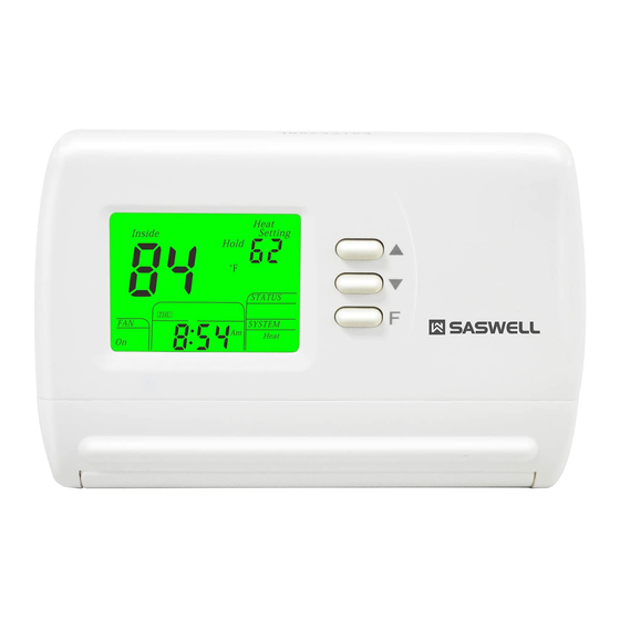
- Page 36 THERMOSTAT LCD DISPLAY...
- Page 37 (10) Filter Alarm: Indicates filter needs to be replaced. (11) Alarm: not used in this model (12) PRGM Run On: Indicates when the thermostat is in the program RUN mode. HOLD: Indicates when the thermostat is in the temperature HOLD mode (13) Heat Setting: Temperature set-point in the Heating Mode Cool Setting: Temperature set-point in the Cooling Mode (14) Set-point temperature display...
- Page 38 (18) Indicates the current system switch position (19) Clock AM/PM indicator (20) Indicates the current time of day, or time of day being programmed (21) Indicates the current day or days being programmed. (22) Indicates the current fan switch position. (23) Indicates when the thermostat is in the PRGM mode.
- Page 43 WARRANTY POLICY Warrants the following: Only cataloged products sold to distributors are warranted to the original purchaser, and to be free from defects in material and workmanship, for a period of one (1) year from the date of purchase, unless specified in writing for a different period.
- Page 44 This warranty does not extend to any product that has been subjected to misuse, abuse, neglect, accidents, alternations, improper installation or use in violation of the printed instructions furnished by us. This warranty neither applies to batteries not deterioration of, nor damage to the product caused by the use of faulty batteries.
Need help?
Do you have a question about the SAS900STK-2 and is the answer not in the manual?
Questions and answers