
Subscribe to Our Youtube Channel
Related Manuals for SIIG AV-GM07U3-S1


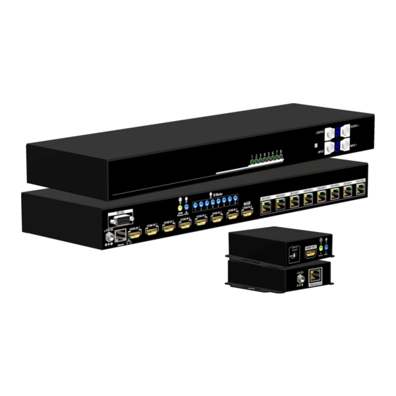
Summary of Contents for SIIG AV-GM07U3-S1
- Page 1 8x8 HDMI Deep Color & Full 3D over single Cat.X Matrix To avoid EMI issue, complete STP Cat6 cable is strongly recommended! P/N: AV-GM07U3-S1...
-
Page 2: Table Of Contents
However, like all electronic equipments, the AV-GM07U3-S1 should be used with care. Please read and follow the safety instructions to protect yourself from possible injury and to minimize the risk of damage to the unit. -
Page 3: Introduction
● Easy installation with rack-mounting and wall-mounting designs for master and receiver respectively ● Fast response time – 2~5 seconds for channel switch PACKAGE CONTENTS ● 1x AV-GM07U3-S1 ● 8x AV-GM07U3-S1-RX ● 9x IR receiver ● 1x IR blaster* ● 1x DC 12V 5A ●... -
Page 4: Specifications
* Additional IR remote controllers and IR blasters can be purchased as optional accessories to control the HDMI sources located separately. SPECIFICATIONS Model Name AV-GM07U3-S1 Technical AV-GM07U3-S1 AV-GM07U3-S1-RX True 8x8 matrix switcher Role of usage Receiver [RX] Transmitter [TX] HDMI Deep Color & full 3D... -
Page 5: Panel Descriptions
-20~60°C [-4~140°F] Relative humidity 20~90% RH [no condensation] PANEL DESCRIPTIONS Transmitting unit ► AV-GM07U3-S1-TX Front Panel Source Status: Input source indicator LED IR SENSOR: IR sensor for receiving the IR commands from IR remote Output Push Button & 7-segment LED: Front panel push buttons used to select the number of display channel &... -
Page 6: Receiving Unit
HDMI Signal IN: Plug in a Cat.X cable HARDWARE INSTALLATION 1. Connect all sources to HDMI Inputs on the 8x8 HDMI over CAT.X matrix master AV-GM07U3-S1. 2. Connect each CAT.X output port on the AV-GM07U3-S1 to respective CAT.X input on the remote... - Page 7 4. Connect IR blaster to the AV-GM07U3-S1 and direct the IR blaster to point towards the built-in IR receiver of the HDMI source devices. 5. Connect the +12V 5A DC power supply to the AV-GM07U3-S1 and +5V 2A DC power supply to the receivers 6.
-
Page 8: Ir Pass-Through
IR BLASTER: IR control on individual display device IR RECEIVER: IR receiver connected here can receive all IR command signals from the IR remote controls of AV-GM07U3-S1 and all other HDMI source devices. CAUTION! Incorrect placement of IR Blaster and Receiver may result in the failure of the IR extenders. -
Page 9: Connection Diagram
You can buy any IR extension cables in the market that are compatible to the definition of the IR sockets for the matrix if necessary for replacement use. However, IR cables longer than 2m (6-ft) may not work. CONNECTION DIAGRAM... -
Page 10: Operation Approach
OPERATION APPROACH Method A: Push-in Button preset save learn default 1. IN/OUT MAP 1) Use the “+”or “-“ output push button to select the number of display 2) Use the “+”or “-“ input push button to select the number of input source “+”: change selected input/output port in ascending order “-”... - Page 11 4) If you push the “output+ (save)”button before the mapping setting is effective, the LED will show “ 一 ”“ 一 ”to quit the Preset Mapping Mode 4. Default EDID Mode 1) Push “input+(default)”button to select the input channel which you want to learn default EDID and then keep pushing “input+(default)”button when you select your desired input channel 2) Push the “+”or “-”...
- Page 12 Method B: IR Remote Control 1. IN/OUT Switch Operation Procedure 7-Segment LED IN/OUT Switch Output Number (1~8) + Input Number (1~8) 1. Press output number key “3” to select Output 3 Ex: Input 2 To Output 3 2. Press input number key “2” to select Input 2 2.
- Page 13 DEFAULT EDID Begin default EDID selection LEARN EDID Begin EDID learning from one output CLEAR Clear the previous IR operation procedure TAKE Trigger the previous setting Reserved Reserved Operation Procedure 7-Segment LED Output Status Status + Output Number (1~8) + Take 1.Press “STATUS”...
- Page 14 2. Press output number key “3” to select Output 3 3.Press “TAKE” button Method C: Software Control through RS-232 port / Ethernet port System Requirement 1) OS Information: MS WinXP/7 2) Baud rates: 9600 3) Software size: 3 MB 4) Minimum RAM requirement: 256 MB Version Button for FW/ SW EDID Button RS-232 Button...
- Page 15 Connect Button In/Out Switch Button Power On/Off Button Mute Output Button 2. Step by step for connecting matrix and controller Step1: Use RS-232 cable to connect the RS-232 port on matrix and PC Step2: Open the software and then choose the correct com port Step3: Click connection button “...
- Page 16 3) Disconnected Status: 8. Connect/Disconnect Button Click this button “ ” to change connection status 9. Power On/Off Button Click this button to power on/off “ ” Power on status(Blue): Click this button to power off device(Standby Mode) “ ” Power off status(Red): Click this button to power on device 10.
- Page 17 1) Learn EDID from Default a) Select Default EDID(1-8 Default EDID) b) Select Input c) Click “Learn” button to learn default EDID 2) Load EDID File to Input a) Select Input b) Click “Load” button to select the EDID file 3) Learn EDID From Display a) Select EDID Port b) Select Input...
- Page 18 5) View EDID content a) Select Input, HDMI output, or From File b) Click “View” button to read the EDID and analysis c) Click “Save As” to save the read EDID as a file on computer 11. Firmware Update Button Step1: Make sure RS-232 is connecting and the connecting status is “...
- Page 19 Step4: Click “Break” button Step5: Quickly pull out and reconnect the power input connector Step6: Click “Start” button and the firmware will start writing 12. Network Button Step1: Make sure the connection status is on connected status “ ” Step2: Connect matrix to network through IP control port Step3: Click “NETWORK”...
- Page 20 13. Mapping Button 1) Save Mapping: a) Select Mapping(1-8) b) Click “Save” button to save current mapping 2) Preset Mapping: a) Select Mapping(1-8) b) Click “Recall” button to recall previous mapping which are saved 3) Rename Mapping: a) Rename the mapping(Mapping1-Mapping8) b) Click “Confirm”...
- Page 21 Click the button on the checkerboard to select Input & Output port User can click the input number button to let all outputs select the same input Ex: All outputs select input 3 16. Mute Output Button Click the circle button to turn off output’s video and audio Ex: Mute Output 2...
-
Page 22: Edid Learning
EDID LEARNING The EDID learning function is only necessary whenever you encounter any display on the HDMI output port that cannot play audio and video properly. Because the HDMI source devices and displays may have various level of capability in playing audio and video, the general principle is that the source device will output the lowest standards in audio format and video resolutions to be commonly acceptable among all HDMI displays. -
Page 24: Warranty
The SELLER will NOT be liable for direct, indirect, incidental, special, or consequential damages resulting from any defect or omission in this manual, even if advised of the possibility of such damages. Also, the technical information contained herein regarding the AV-GM07U3-S1 features and specifications is subject to change without further notice.
Need help?
Do you have a question about the AV-GM07U3-S1 and is the answer not in the manual?
Questions and answers