Advertisement
Quick Links
88 5023 95C
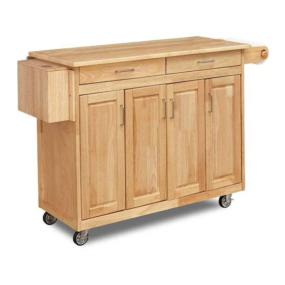
Kitchen Island with
Breakfast Bar
IMPORTANT NOTE
Carefully remove all the parts from the carton and put
them individually on a soft cloth to prevent scratches
or other damages occuring to the parts.
We have taken great care in the design of this
product and request that you carefully and strictly
follow our assembly instructions to ensure a
completed product as it was designed.
PART LIST
A.
Top
1 pc.
F.
G.
Back Panel
Back Piece
1 pc.
2 pcs.
M.
Divider
1 pc.
N. & O.
Drawer
2 pcs.
(For Drawers, packed in a separate carton)
HARDWARE LIST
Hex Wrench
1 pc.
Caster
two lock
Small
two non-lock
Hex Wrench
4 pcs.
1 pc.
Tools Required For Assembly : Phillips screwdriver
Home Styles Consumer Assistance Line 888-680-7460 and 877-831-0319
B.
Side Panel
1 pc.
H.
Back Stretcher
1 pc.
I.
Front Piece
1 pc.
P.
Shelf
2 pcs.
Q.
Gate Leg
Shelf
1 pc.
Head Cap Bolt
13 pcs. (+1 extra)
Wood Screw
for Caster and
Gate Leg
20 pcs. (+1 extra)
servicedesk@homestyles-furniture.com
C.
Middle Panel
2 pcs.
J.
Base
1 pc.
Handle Arm
2 pcs.
R.
1 pc.
Round Arm
Cam Lock Screw
Drawer
6 pcs. (+1 extra)
Pull Handle
4 pcs.
Machine Screw
Cam Lock
8 pcs.
6 pcs. (+1 extra)
D.
Side Panel
1 pc.
E.
Back Panel
2 pcs.
K.
L.
Door
Door
2 pcs.
2 pcs.
S.
T.
Knife Box
1 pc.
1 pc.
Adjustable Pin
12 pcs. (+1 extra)
Wood Plug
6 pcs.(+2 extra)
Revised date : 23Mar2011
U.
Advertisement

Subscribe to Our Youtube Channel
Related Manuals for Home Styles 5023-95


Summary of Contents for Home Styles 5023-95
- Page 1 6 pcs.(+2 extra) two non-lock 8 pcs. Hex Wrench 6 pcs. (+1 extra) 20 pcs. (+1 extra) 4 pcs. 1 pc. Tools Required For Assembly : Phillips screwdriver Home Styles Consumer Assistance Line 888-680-7460 and 877-831-0319 Revised date : 23Mar2011 servicedesk@homestyles-furniture.com...
- Page 2 Assembly Instructions 2/4 IMPORTANT Do not tighten up all the screws until each part is properly assembled. You should keep Hex Wrench in the safe place as you may need to tighten up the Head Cap Bolts in the future. Wood Screw STEP 1 Wood Screw...
- Page 3 Assembly Instructions 3/4 STEP 4 Attach Gate Leg (R) at the back of unit with Wood Screws. (See figure 2) (Figure 2) Wood Screw Wood Screw Head Cap Bolt STEP 5 Adjustable Pin Assemble Handle Arm (S) to Side Panel (D) with Head Cap Bolts. Slide Round Arm (T) into place.
- Page 4 Assembly Instructions STEP 6 Cam Lock Screw Put Cam Lock Screws into the pre-drilled holes at Top (A). Place Top (A) onto the unit, using Cam Locks. (See figure 3) Cam Lock (Figure 3) Cam Lock Machine Screw (Figure 4) STEP 7 Assemble Pull Handles to Door (K) and (L) Spring Pin...
-
Page 5: Part List
88 5023 95 Drawer (N) N5 O5 Drawer (O) PART LIST HARDWARE LIST N2, O2. N3, O3. Drawer Wood Screw (short) Back Part Pull Handle Side Part for Base Part 1 pc.for each drawer 2 pcs. 1 pc.for each drawer 12 pcs.
Need help?
Do you have a question about the 5023-95 and is the answer not in the manual?
Questions and answers