Table of Contents
Advertisement
Quick Links
88502395 C
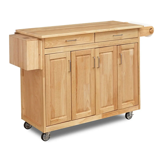
Kitchen Island with
Breakfast Bar
Thank you for purchasing our quality products.
Please carefully check the quantity of the parts
and hardware. Please also read this assembly
instructions until you understand clearly how to
put the parts together then start assembling
step by step.
PART LIST
A.
Top
1 pc.
H.
Back Stretcher
1 pc.
Stretcher
J.
Bottom
1 pc.
P.
Small Shelf
2 pcs.
Caster
with and
without brake
4 pcs.
B.
Side Frame L.
1 pc.
I.
Front
1 pc.
K.
Door L.
2 pcs.
R.
Q.
Gate Leg
Large Shelf
1 pc.
1 pc.
Cam Lock Screw
Head Cap Bolt
6 pcs. (+1Extra)
13 pcs. (+1Extra)
Cam Lock
Hex Wrench
6 pcs. (+1Extra)
1 pc.
Thai Patent Pending Numbers 074801
C.
D.
Middle Frame
Side Frame R.
2 pcs.
1 pc.
L.
M.
Door R.
Drawer
2 pcs.
Divider.
1 pc.
S.
Handle Arms
2 pcs.
Pull Handle
4 pcs.
Machine Screw
for Pull Handle
8 pcs.
Casual Attire For Today's Home
E.
F.
Small
Large
Back Panel
Back Panel
2 pcs.
1 pc.
N.
O.
KD. Drawer L.
KD. Drawer R.
1 pc.
1 pc.
(For Drawer N&O Packed in separate carton
with hardware and assembly instructions.)
T.
Round Arm
1 pc.
Wood Screw
20 pcs. (+2 Extra)
Adjustable Pin
12 pcs. (+2Extra)
G.
Back Post
2 pcs.
U.
Knife Box
1 pc.
Wood Plug
6 pcs.
(+2 Extra)
Advertisement
Table of Contents

Subscribe to Our Youtube Channel
Related Manuals for Home Styles 88502395 C


Summary of Contents for Home Styles 88502395 C
- Page 1 88502395 C Kitchen Island with Breakfast Bar Thank you for purchasing our quality products. Please carefully check the quantity of the parts and hardware. Please also read this assembly instructions until you understand clearly how to put the parts together then start assembling step by step.
- Page 2 Assembly Instructions 2/3 IMPORTANT Do not tighten up all the screws until each part is properly assembled. You should keep Hex Wrench in the safe place as you may need to tighten up the Head Cap Bolts in the future. STEP 1 Attach 4 Casters to the under side of the Bottom (J), put the 2 Casters with...
- Page 3 Assembly Instructions 3/3 STEP 4 Place the Gate leg (R) on the rear and hold on back frame with Wood Screws. Holding Gate Leg and rear frame with Wood Screw STEP 5 Attach the Knife Box (U) to the Side Frame (B) with the Head Cap Bolts.
- Page 4 88502395 C Drawer (N) Drawer (O) Unit Part List HARDWARE LIST N4,O4. Side Part(R.) Wood Screw /” Pull Handle (for Bottom Part) 1 piece for each 2 pieces. 12 pieces. drawer. N1,O1. N2,O2. N5,O5. Front Part Back Part N3,O3. Bottom Part 1 piece for each Side Part(L.)
Need help?
Do you have a question about the 88502395 C and is the answer not in the manual?
Questions and answers