Table of Contents
Advertisement
Quick Links
Advertisement
Table of Contents

Related Manuals for Aqua Lung ODYSSEA


Summary of Contents for Aqua Lung ODYSSEA
- Page 1 ODYSSEA (EXPORT) (NON-MAGNETIC) TECHNICAL MANUAL Rev. 11/17...
- Page 2 Aqua Lung International. It may not be distributed through the internet or computer bulletin board systems without prior consent in writing from Aqua Lung International.
-
Page 3: Table Of Contents
CONTENTS INTRODUCTION ..........................5 GENERAL PRECAUTIONS AND WARNINGS ................7 PRODUCT DESCRIPTION ......................8 SYSTEM LAYOUT .......................... 8 BC Air Breathing......................... 8 Pocket & Equipment Retainers ....................9 Universal Connector Caps ......................9 Auxiliary Air Cylinder ........................9 General Filling Procedures......................9 Filling the Auxiliary Air Cylinder with a Fill Adapter.............. - Page 4 Odyssea (Export) Technical Manual INSTRUCTIONS FOR BC REPAIR KIT (EXPORT) ..............33 TABLE 1: LIST OF TOOLS ......................34 TABLE 2: TORQUE SPECIFICATIONS ..................36 TABLE 3: RECOMMENDED CLEANERS, LUBRICANTS AND SEALANTS ......36 PROCEDURE A: CLEANING AND LUBRICATING ..............37 AIRWAY AND CYLINDER VALVE CONNECTOR EXPLODED VIEW .........38 CYLINDER VALVE EXPLODED VIEW ..................39...
-
Page 5: Introduction
NOT attempt to substitute an Aqua Lung® part This manual provides factory prescribed procedures with another manufacturer’s, regardless of any for the correct service and repair of the Aqua Lung similarity in shape or size. product described in this manual. It is not intended to be used as an instructional manual for untrained 5. - Page 6 Odyssea (Export) Technical Manual CAUTION: Use only a plastic or brass o-ring removal tool when removing o-rings to prevent damage to the sealing surface. Even a small scratch across an o-ring sealing surface could result in leakage. Once an o-ring sealing surface has been damaged, the part must be replaced with new.
-
Page 7: General Precautions And Warnings
WARNING: Repair, service or disassembly must not be attempted by persons who are not factory trained and authorized by Aqua Lung International. Unauthorized service will render the warranty null and void. WARNING: A BC is NOT a life jacket or rescue device! It is not designed to provide face-up flotation in all situations;... -
Page 8: Product Description
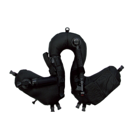
Odyssea (Export) Technical Manual PRODUCT DESCRIPTION The Odyssea is specifically designed for military use with all types of back or chest worn underwater breathing apparatus (UBA), semi-closed circuit or closed circuit rebreathers. The Odyssea features a cylinder connector that allows you to attach an auxiliary air cylinder and inflate the BC with compressed breathing air. -
Page 9: Pocket & Equipment Retainers
Auxiliary Air Cylinder A cylinder is attached to the Odyssea by means of a threaded hand fitting. Air is added to the BC by opening the cylinder valve (Fig. 2). Required for closed circuit and semi-closed circuit diving. -
Page 10: Filling The Auxiliary Air Cylinder With A Fill Adapter
Filling the Auxiliary Air Cylinder with a Fill Adapter NOTE: The Odyssea does not include a fill adapter. This adapter (PN 840817) may be purchased separately (Fig. 3). - Page 11 While supporting the auxiliary air cylinder with one hand, place the yoke of the fill adapter over the cylinder valve to align the inlet fitting flush against the valve o-ring. Screw the fill adapter yoke screw into the small dimple on the backside of the cylinder valve finger-tight (Fig. 5). Relief Plug Yoke Screw Fig.
-
Page 12: Attaching The Auxiliary Air Cylinder
Odyssea (Export) Technical Manual Attaching the Auxiliary Air Cylinder 1. Before attaching the cylinder, inspect the o-ring located Check O-ring at the tip of the cylinder valve connector (Fig. 6). Fig. 6 2. Insert the cylinder into the retaining sleeve and align the threaded valve outlet with the cylinder valve connector. -
Page 13: Inflation Methods
INFLATION METHODS Inflation Using the Oral Inflator To orally inflate your BC (Fig. 8), place your lips on the oral inflator mouthpiece (A) and exhale a small amount of air into the mouthpiece to purge any water that may still be in the housing. While continuing to exhale into the mouthpiece, depress the oral inflator button (B) to inflate the BC. -
Page 14: Deflation Using The Rapid Exhaust Valve (Rev)
Odyssea (Export) Technical Manual Deflation Using the Rapid Exhaust Valve (REV) Inside the inflators spiral hose is a braided spectra cord that attaches the inflator to the dual valve at the top of the airway assembly. You can vent air from the BC by firmly pulling straight down on the lower inflator assembly (DO NOT use excessive force). -
Page 15: Donning And Adjustment Procedures
DONNING & ADJUSTMENT PROCEDURES Donning and Adjustment (Figs. 12 & 13) 1. One end of the back strap has a male quick-release buckle (A). Connect the male buckle to the female buckle at the top of the BC. Secure the excess webbing through the 3-bar slide (B). -
Page 16: Pre-Dive Inspection Checklist
Odyssea (Export) Technical Manual PRE-DIVE INSPECTION CHECKLIST Diver Name_____________________________ Date_____________ Odyssea Number_________ WARNING: Before each use, the BC must be given a thorough visual inspection and functional test. NEVER dive with a BC that shows signs of damage to its bladder or valves until it has received a complete inspection and service. -
Page 17: Post Dive Inspection Checklist
POST-DIVE INSPECTION CHECKLIST Diver Name_____________________________ Date_____________ Odyssea Number_________ NOTE: Following the post-dive maintenance procedures is essential to ensure the BC remains in proper working condition. CAUTION: • Avoid prolonged exposure to sunlight and extreme heat. Nylon fabric can quickly fade when exposed to the sun’s ultraviolet rays and extreme heat may damage the welded bladder seams. -
Page 18: Bc Bladder Removal
Odyssea (Export) Technical Manual BC BLADDER REMOVAL 1. Unscrew the knurled nut on the cylinder valve connector (58) and remove the cylinder (59) from the retaining sleeve. After the cylinder has been removed, loosen the cylinder valve connector and remove it from the manifold. -
Page 19: Bc Bladder Installation
BC BLADDER INSTALLATION 4. Turn the cylinder valve on and inflate the bladder until the over pressure relief valve (OPRV) releases the excess air from the bladder. Turn off cylinder and remove the cylinder from the BC. Check both caps (62), dump valve (63), airway (57) and cylinder valve connector 1. -
Page 20: Airway Maintenance Procedures
Odyssea (Export) Technical Manual AIRWAY MAINTENANCE PROCEDURES 3. Pull back the spiral hose (24) from the airway body (30). Press the pin (28) out from one side using a pin punch or similar tool to release the braided spectra cord (23). Remove the spiral hose from the dual valve body (13). - Page 21 CAUTION: Do not attempt to disassemble individual NOTE: The cap is bonded to the dual valve body with a small amount of Loctite 425 or 480. It will be necessary to parts of the airway body assembly. Attempting to do so separate this bond prior to performing further disassembly will cause permanent damage and the airway body will by carefully following the procedure outlined below.
-
Page 22: Airway Reassembly
Odyssea (Export) Technical Manual 13. Locate the two holes on opposite sides of the dual valve body (13) NOTE: Before performing any assembly, it is important which hold the arms of the poppet guide (21). Remove the poppet to inspect all parts, both new and those that are being... - Page 23 7. Install mouthpiece (29) onto 4. Set the cage (36) with the the airway body (30) with the fingers facing out over the push curved end facing out. Ensure button (35). Place the airway the mouthpiece fits into the body (30) face down on a clean groove on the airway body.
- Page 24 Odyssea (Export) Technical Manual b. Compress the poppet guide (21) with the forked end out onto 13. Squeeze the arms of the poppet guide (21) so that the the poppet holding fixture. The hole in the poppet stem (19) should ears fit inside the dual valve body (13), and press the poppet be in-line with the small notches on the poppet guide.
- Page 25 17. Ensure the inside line on 21. Insert retaining pin (28) half way into one hole of the airway body the bottom vent slot of the cap (30). Slide the spiral hose (24) back and capture both loop ends of (17) lines up with the seam on the braided spectra cord (23) using your thumb and index finger the dual valve body (13).
-
Page 26: Cylinder Valve Connector Maintenance Procedures
Odyssea (Export) Technical Manual C Y L I N D E R VA LV E C O N N E C T O R 4. Remove o-rings (1 & 7) from the valve reducing connector (2). MAINTENANCE PROCEDURES NOTE: Before performing any disassembly, refer to the exploded parts drawing which references all mandatory replacement parts. -
Page 27: Cylinder Valve Connector Reassembly
5mm hex key adapter, tighten the valve reducing connector into supple, and free of any blemish. the connector handtight, then an additional 1/4 turn. WARNING: Use only genuine Aqua Lung parts, sub- ® assemblies and components whenever assembling any Aqua Lung product. -
Page 28: Cylinder Valve Maintenance Procedures
Odyssea (Export) Technical Manual CYLINDER VALVE MAINTENANCE 4. Place the valve body (52) in a vise. Unscrew the valve seat adapter (50) from the valve body using a 3/8” flex handle PROCEDURES drive and 5mm hex key adapter. NOTE: Before performing any disassembly, refer to the... - Page 29 7. Unscrew the valve seat (49) from the valve body (52) using the spindle (47) and oldham (48). 8. Using your fingers, remove the washer (45) from the spindle (47). Remove o-ring (46) from the groove on the spindle. NOTE: If the washer does not come out on the spindle, check for it inside the valve plug.
-
Page 30: Cylinder Valve Reassembly
Odyssea (Export) Technical Manual 3. Install o-ring (44) onto the valve plug (43). Ensure it is seated into NOTE: Before performing any reassembly, it is important the groove on the plug below the shoulder. Screw the valve plug to inspect all parts, both new and those that are being back into the valve body (52) until handtight. -
Page 31: Cylinder Valve Testing Procedure
FINAL ASSEMBLY AND TESTING 7. Install o-ring (53) onto valve body (52). Lightly lubricate the threads of the valve body. Secure cylinder (54) with strap wrench and screw the cylinder valve into the cylinder until handtight. Using a 27mm (1-1/16 inch) crowfoot along with a Newton Meter torque wrench, WARNING: Protective eyewear must be worn at all tighten the valve assembly into the cylinder to 30 Nm (22 ft lb). - Page 32 Odyssea (Export) Technical Manual 4. While holding the dual-valve assembly secure, firmly grasp the 8. Connect a full cylinder to the cylinder valve connector. Open the airway body assembly (30) and pull it in a straight line directly away cylinder valve to inflate the bladder until the over pressure relief valve from the dual-valve assembly.
-
Page 33: Instructions For Bc Repair Kit (Export)
Instructions for BC Repair Kit (Export) 3. Apply a generous coat of Weld-On® 4784 adhesive to the material of the BC surrounding the hole or tear. Allow this preliminary coat to set for at least twenty four hours. WARNING: Do not attempt to perform these procedures using patches or adhesive other than those mentioned in the BC Repair Kit pn 42653. - Page 34 Odyssea (Export) Technical Manual TABLE 1: LIST OF TOOLS PART # DESCRIPTION APPLICATION Adjustable Face 129198 Removal/Installation of Push Button (35) Spanner Tank Fill 840817 Charging Cylinder Adapter GERS O-ring Tool Kit 944022 (Brass) Removal/Installation of O-rings O-Ring Tool 103102...
- Page 35 TABLE 1: LIST OF TOOLS (CONTINUED) PART # DESCRIPTION APPLICATION Loctite 414 Superbonder (1 oz Bottle) Adhesive Applied to Valve Reducing Connector (2) Threads Loctite 242 Adhesive Applied to Valve Seat Adapter (50) Loctite 425 or 480 Adhesive Applied to Cap (17) and Large Stem (31) Threads Gasgacinch Sealing Spiral Hose (24) Cord Hook...
- Page 36 Odyssea (Export) Technical Manual TABLE 2: TORQUE SPECIFICATIONS PART # DESCRIPTION / KEY ITEM # TORQUE 840923 Plug, Valve (43) 15 Nm (132 in lb) 840917 Body, Valve (52) 30 Nm (22 ft lb) 840919 Adapter, Metric, Valve Seat (50)
-
Page 37: Procedure A: Cleaning And Lubricating
PROCEDURE A: CLEANING AND LUBRICATING Cleaning Brass & Stainless Steel Parts 1. Pre-clean in warm, soapy water* using a nylon bristle tooth brush. 2. Thoroughly clean parts in an ultrasonic cleaner filled with soapy water. If there are stubborn deposits, household white distilled vinegar (acetic acid) in an ultrasonic cleaner will work well. -
Page 38: Airway And Cylinder Valve Connector Exploded View
Odyssea (Export) Technical Manual AIRWAY AND CYLINDER VALVE CONNECTOR EXPLODED VIEW Loctite 101338 Connector, Cylinder Valve Export, Straight, (Non-Mag) 425 or 480 Key # AQA PN *AQF PN Description 840556 840556 Kit, O-rings Cylinder Connector 1 820038P 124704 O-ring (20 pk) -
Page 39: Cylinder Valve Exploded View
CYLINDER VALVE EXPLODED VIEW 840970 Cylinder Valve (Non-Mag) w/ .43L Cylinder Key # Description AQF PN 840971 Kit, O-rings & Seat Cylinder 840922 Nut, Handwheel 480952 Spring 228176 Handwheel 213421 Washer 840923 Plug, Valve 15 Nm 850218 O-ring 840523 Washer 840163 O-ring 840921 Spindle 480932 Oldham... -
Page 40: Odyssea Components
Connector, Cylinder Valve Export, Straight (Non-Mag) 1 840970 Cylinder, .43L w/ Non-Mag Valve (Export) 394093 Back / Crotch Strap Kit, Odyssea 394089 Back / Chest / Waist Strap Kit, Odyssea 15665 Cap, Universal Connector 490620 Dump Valve Conv Kit, ACME (Non-Mag) Accessories... -
Page 41: Technical Data
TECHNICAL DATA Annual Maintenance The Odyssea is subject to annual maintenance. All service kit parts indicated on the component exploded view must be replaced annually, even if they appear to be in good condition. Composition: (4) Gasket (Key # 12). -
Page 42: Maintenance Notes
Odyssea (Export) Technical Manual MAINTENANCE NOTES... -
Page 43: Warranty Information
® ™ Aqua Lung America warrants to the original purchaser for a period of one year from the date of purchase that the product will be free from defects in material and workmanship; provided that it receives normal use, proper care, and prescribed dealer service subject to those restrictions stated below. This limited warranty is extended only to the original purchaser for purchases made from an authorized Aqua Lung ®... - Page 44 ODYSSEA (EXPORT) (NON-MAGNETIC) 2340 Cousteau Court • Vista, CA 92081 Phone (760) 597-5000 • Fax (760) 597-4900 www.aqualung.com/militaryandprofessional ©2017 Aqua Lung International...
Need help?
Do you have a question about the ODYSSEA and is the answer not in the manual?
Questions and answers