Advertisement
Quick Links
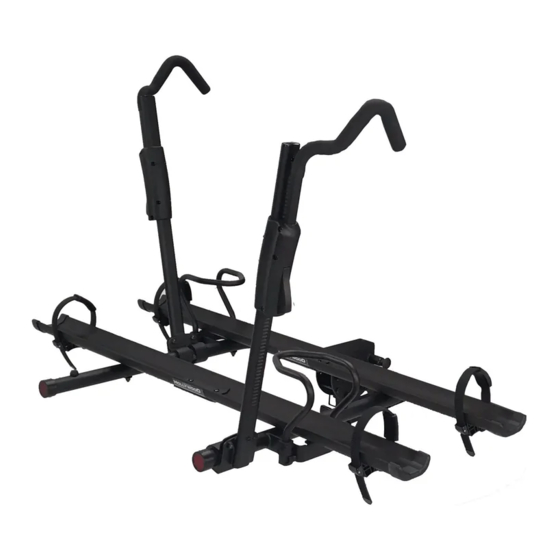
HOLLYWOOD RACKS
•
Model HR3000-E (1 ¼" – 2" hitches) 2 BIKE CAPACITY, MINIMUM CLASS II HITCH REQUIRED
•
Model HR3500-E (2" hitches only) 2 BIKE CAPACITY, MINIMUM CLASS II HITCH REQUIRED
Weight Limit 65 lbs/29.5 kg per bike
Maximum Bike Tire Width: 4.5"
Not to be used on any trailer, fifth wheel or towed vehicle
Not for use with gas powered bikes or motorcycles
IF YOU HAVE PURCHASED THE TRS E-BIKE ADAPTER IN A
SEPARATE BOX AS AN UPGRADE KIT, PLEASE REFER TO THE
ATTACHED ADDITIONAL INSTRUCTION SHEET BEFORE ASSEMBLY.
Assembly guide for TRS (Tire Retention System) E-bike rack
HOLLYWOODRACKS.COM
Advertisement

Related Manuals for Hollywood Racks HR3000-E


Summary of Contents for Hollywood Racks HR3000-E
- Page 1 HOLLYWOOD RACKS Assembly guide for TRS (Tire Retention System) E-bike rack • Model HR3000-E (1 ¼” – 2” hitches) 2 BIKE CAPACITY, MINIMUM CLASS II HITCH REQUIRED • Model HR3500-E (2” hitches only) 2 BIKE CAPACITY, MINIMUM CLASS II HITCH REQUIRED Weight Limit 65 lbs/29.5 kg per bike...
- Page 2 LOCKING HITCH PIN & CABLE WHEEL TRAY (HALF) (INCLUDED WITH HR3500-E) UPPER PLATE 1 ¼ -2” HITCH TUBE (INCLUDED J1, J2 TIRE CAGE CAPS WITH MODEL HR3000-E) RATCHET STRAP INNER SUPPORT TUBE LOCKING HITCH PIN & CABLE OUTER SUPPORT TUBE (INCLUDED WITH HR3000-E)
- Page 3 8.5mm ID socket screw, M6x40mm washer, 6.5mm ID nylock nut, M6 Phillips head screw, M6 4mm Allen key, HR3000-E only socket head bolt, ½-13 x 85mm nylock nut, ½-13 bushing, ½” ID washer, 13.5mm ID 8mm Allen key 5mm Allen Key hex bolt, 5/16-18 x 1.5”...
- Page 4 Step 1: Assemble main frame to hitch tube. Per Fig. 5, prepare the components on a flat table or work surface. Per Fig. 6, locate the Spring Pins and holes in the folding bracket Fig. 5 Note: it will be easier to do this part of the assembly on a flat surface or work table. Fig.
- Page 5 Step 2: Install rack into hitch Step 2A: For model HR3500 (2” “no-wobble system” version, locking hitch pin included): Install Hitch Tube (B) into vehicle’s trailer hitch Fig. 10: Slide the rack in the folded-up position into the trailer hitch until it stops. Fig 10: Remove locking head from hitch pin B1 and insert pin through the hole in the trailer hitch and hitch tube until it passes through the opposite side.
- Page 6 Step 3: Fold-Up/Fold-Down Fig. 12: From the rack’s “folded” position folded to “in use” position, pull the rear spring pin out and rotate the rack down until the front spring pin clicks into place. To return the rack to its folded position, pull the front spring pin out and rotate the rack up until the...
- Page 7 Step 5: Install Tire Hooks Per Fig. 17: Prepare the tire hooks, washers f-f and screws k-k (Phillips screwdriver required). Use Inside Tire Hook E for inner bike position (closest to car). Slide the Inside Tire Hook E down over the outer ratchet arm. Note the trigger faces the driver’s side of the vehicle.
- Page 8 Step 7: Install wheel support tubes: Fig. 20-22: Place large washer g-g on the round tube frame. Then place the inside wheel support tube L on top of the washers, aligning the holes. The “long end” of the support tube must be resting on top of the bracket as shown in Fig.
- Page 9 Step 9: Install wheel Fig. 26 trays: Fig 27: Slide the aluminum wheel trays onto the protruding bolt-head. Note ratchet straps should be on the “far side” of the tray. Repeat for the other side, allowing the trays to meet in the center of the support tubes.
- Page 10 Step 10: Tilt-Down Function Per Fig. 30 & 31: Lift up the rack and remove the snapper pin. Pull out the front Fig. 30 spring pin and hold the main frame while it tilts down into position. To return the rack to its in-use or folded up position, lift the main frame until the front spring pin clicks into place.
- Page 11 Fig. 34 Fig. 33 Fig. 37 Fig. 35 Fig. 36 Fig. 39 Fig. 38 DOUBLE CHECK BEFORE DRIVING THAT HOOKS ARE FIRMLY ENGAGED AGAINST TIRE AND RATCHET WHEEL STRAPS ARE FIRMLY ATTACHED. DRIVE SLOWLY ON BUMPY OR DIRT ROADS. THIS PRODUCT IS NOT TO BE USED ON ANY TRAILER, FIFTH WHEEL OR TOWED VEHICLE.
- Page 12 Hollywood Racks will remedy defects in materials and workmanship by repairing or replacing (at its option) a defective part without charge for labor or parts. Hollywood Racks may elect (at its option) to issue a refund equal to the purchase price paid for the product.
Need help?
Do you have a question about the HR3000-E and is the answer not in the manual?
Questions and answers