Table of Contents
Advertisement
Quick Links
This document is the user's guide for the TPS65982 Evaluation Module (TPS65982-EVM). The
TPS65982-EVM allows for evaluation of the TPS65982 IC as part of a stand-alone testing kit and for
development and testing of USB Type-C and Power Delivery (PD) end products.
1
2
3
...................................................................................................................
4
4.1
Using the TPS65986 on the TPS65982-EVM
..........................................................................................................................
5
5.1
Header, Jumper, Switch, Push Button and Test Point Descriptions
5.2
5.3
Getting Started Using the TPS65982-EVM
...................................................................................................................
6
7
8
9
Tiva, Code Composer Studio, Thunderbolt are trademarks of Texas Instruments.
SLVUAF8C - June 2015 - Revised November 2015
Submit Documentation Feedback
............................................................................................................
..............................................................................................
..................................................................................................
................................................................................................................
.............................................................................................................
.......................................................................................................
Copyright © 2015, Texas Instruments Incorporated
SLVUAF8C - June 2015 - Revised November 2015
TPS65982 Evaluation Module
Contents
...............................................................................
...................................................................
...................................................................
User's Guide
.........................................
TPS65982 Evaluation Module
4
4
4
5
5
8
8
10
11
29
31
35
38
1
Advertisement
Table of Contents

Subscribe to Our Youtube Channel
Related Manuals for Texas Instruments TPS65982


Summary of Contents for Texas Instruments TPS65982
-
Page 1: Table Of Contents
This document is the user’s guide for the TPS65982 Evaluation Module (TPS65982-EVM). The TPS65982-EVM allows for evaluation of the TPS65982 IC as part of a stand-alone testing kit and for development and testing of USB Type-C and Power Delivery (PD) end products. - Page 2 ..........Writing a Flash Image Using an Aardvark SPI Programmer ........Wire Aardvark to SPI Pins for Flash on the TPS65982-EVM board ................... Run “Flash Center”.exe ......................Add Adapter ................... Choose Target (Device Type) ....................Load Binary File ..................
- Page 3 ......................Configuration ID 14 ......................Configuration ID 15 ......................Bill of Materials SLVUAF8C – June 2015 – Revised November 2015 TPS65982 Evaluation Module Submit Documentation Feedback Copyright © 2015, Texas Instruments Incorporated...
-
Page 4: About This Manual
About this Manual This user’s guide describes the TPS65982-EVM. This guide contains an introduction, setup instructions, the EVM schematic, top and bottom board layouts and component views, internal VDD and GND plane layouts, and a bill of materials (BOM). -
Page 5: Introduction
USB Type-C cable. The TPS65982 detects the plug event and/or presence of another Type-C product on the CC1 or CC2 pin and provides or consumes power on the VBUS pin. The TPS65982-EVM also supports dead battery mode and can be powered by another TPS65982-EVM or other USB Type-C power provider. -
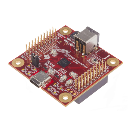
Page 6: Tps65982-Evm (Top View)
Introduction www.ti.com Figure 1. TPS65982-EVM (Top View) TPS65982 Evaluation Module SLVUAF8C – June 2015 – Revised November 2015 Submit Documentation Feedback Copyright © 2015, Texas Instruments Incorporated... -
Page 7: Tps65982-Evm (Bottom View)
Introduction www.ti.com Figure 2. TPS65982-EVM (Bottom View) SLVUAF8C – June 2015 – Revised November 2015 TPS65982 Evaluation Module Submit Documentation Feedback Copyright © 2015, Texas Instruments Incorporated... -
Page 8: Setup
1 of S1. Bit [B0] is pulled high when the upper-most switch is pushed to the right-hand side, pin 8 of S1. Bit [B1] is connected to the DEBUG3 pin of the TPS65982 IC (U2) and is pulled low when the middle- upper switch is pushed to the left-hand side, pin 2 of S1. - Page 9 Type-C receptacle (J1). When a Type-C cable is plugged in upside-down, the CC2 signal is connected to the CC wire of the cable and the CC1 pin of the TPS65982 IC (U2). When a cable is plugged in right-side up, the CC2 signal is connected to the VCONN wire of the cable and the CC2 pin of the TPS65982 IC (U2).
-
Page 10: Led Descriptions
5.2.5 D6: Consumer (CONS) Indicator (White LED) LED D6, labeled CONS, is an indicator of the consumer/provider role which is ON when the TPS65982 IC (U2) has negotiated a USB PD contract to be a power consumer, or sink. 5.2.6... - Page 11 Table 2), the TPS65982-EVM will negotiate a USB PD contract for 5 V at 3 A, 12 V at 3 A, 12–20 V at 3 A, 20 V at 3 A, or 20 V at 5 A and will provide power to portions of the system depending on whether the PP_EXT external FET or PP_HV internal FET is used to sink power.
- Page 12 LED indicators may be ON or blinking ON or OFF: LED D8 (5V) or LED D9 (HV). If the TPS65982 is acting as a power provider and the voltage on VBUS is 5 V, LED D8 (5V) will be ON.
-
Page 13: Tps65982-Evm Configuration Table
2, and is as simple as changing the position of the top 3 DIP switches on switch bank S1. Resetting the TPS65982 IC (U2), reloading the FW in the Flash IC (U1), and re-initializing by reading the S1 DIP switch positions can be accomplished by pressing and releasing push-button S3. A detailed description of each of the TPS65982-EVM configurations settings controlled by S1 can be found in Section 5.3.3.1... -
Page 14: Configuration Id 0
5.3.3.1.1 Overview The TPS65982-EVM will power-on and initialize into configuration ID 0 when all 4 of the DIP switches [B0:B3] on switch bank S1 are pushed to the left-hand side. Configuration ID 0 is designed to model a docking system application. -
Page 15: Configuration Id 1
EVM using configuration ID 4 for providing power and entering DisplayPort alternate mode. To test this configuration as a power consumer which enters USB2.0 and 3.1 for data, pair it with a TPS65982-EVM using configuration ID 6. These TPS65982-EVM configurations respectively emulate dock, dongle, and charger-adapter applications and the same performance is expected when connected to actual applications of these products. -
Page 16: Configuration Id 2
EVM using configuration ID 4 for providing power and entering DisplayPort alternate mode. To test this configuration as a power consumer which enters USB2.0 and 3.1 for data, pair it with a TPS65982-EVM using configuration ID 6. These TPS65982-EVM configurations respectively emulate dock, dongle, and charger-adapter applications and the same performance is expected when connected to actual applications of these products. -
Page 17: Configuration Id 3
EVM using configuration ID 4 for providing power and entering DisplayPort alternate mode. To test this configuration as a power consumer which enters USB2.0 and 3.1 for data, pair it with a TPS65982-EVM using configuration ID 6. These TPS65982-EVM configurations respectively emulate dock, dongle, and charger-adapter applications and the same performance is expected when connected to actual applications of these products. -
Page 18: Configuration Id 4
[B2] on switch bank S1 is pushed to the right-hand side. Configuration ID 4 is designed to model a dongle application. A TPS65982-EVM configured as a dongle is capable of consuming (sinking) power only. A fully-featured Type-C port on a dongle can be capable as an upstream-facing port (UFP) for DisplayPort video, which is also emulated by this EVM configuration. -
Page 19: Configuration Id 5
[B3] on switch bank S1 is pushed to the left-hand side. Configuration ID 5 is designed to model a Thunderbolt docking system application. A TPS65982-EVM configured as a dock is capable of providing (sourcing) power. The fully-featured Type- C port of a dock which faces a monitor can be a downstream-facing port (DFP) for DisplayPort video and Thunderbolt Alternate Mode video+data, which is also emulated by this EVM configuration. -
Page 20: Configuration Id 6
This configuration pairs ideally with a TPS65982-EVM using configuration ID 7 for providing power and enters USB2.0 and 3.1 mode for data by default. This configuration is also compatible with a TPS65982- EVM using configuration ID 2 or 3 for providing power and enters USB2.0 and 3.1 mode for data by default. -
Page 21: Configuration Id 7
5.3.3.8.1 Overview The TPS65982-EVM will boot up and initialize into configuration ID 7 when [B0], [B1], and [B2] of the DIP switches on switch bank S1 are pushed to the right-hand side and [B3] is pushed to the left. Configuration ID 7 is designed to model a high-power bus-powered device application. -
Page 22: Configuration Id 8
5.3.3.9.1 Overview The TPS65982-EVM will boot up and initialize into configuration ID 8 when the switches [B0], [B1], and [B2] on switch bank S1 are pushed to the left-hand side and switch [B3] on switch bank S1 is pushed to the right-hand side. -
Page 23: Configuration Id 9
5.3.3.10.1 Overview The TPS65982-EVM will boot up and initialize into configuration ID 9 when [B0] and [B3] DIP switches on S1 are pushed to the right-hand side and switch [B1] and [B2] on switch bank S1 is pushed to the left- hand side. -
Page 24: Configuration Id 10
5.3.3.11.1 Overview The TPS65982-EVM will boot up and initialize into configuration ID 10 when the DIP switches [B1] and [B3] on switch bank S1 are pushed to the right-hand side and [B0] and [B2] on switch bank S1 is pushed to the left-hand side. -
Page 25: Configuration Id 11
Table 14. Configuration ID 11 5.3.3.12.1 Overview The TPS65982-EVM will power-on and initialize into configuration ID 11 when [B0], [B1] and [B3] on switch bank S1 are pushed to the right-hand side and [B2] is pushed to the left. Configuration ID 11 is designed to model a docking system application. -
Page 26: Configuration Id 12
5.3.3.13.1 Overview The TPS65982-EVM will boot up and initialize into configuration ID 12 when [B0] and [B1] on switch bank S1 is pushed to the left-hand side and [B2] and [B3] on switch bank S1 is pushed to the right-hand side. -
Page 27: Configuration Id 13
5.3.3.14.1 Overview The TPS65982-EVM will boot up and initialize into configuration ID 13 when [B1] on switch bank S1 is pushed to the left-hand side and [B0], [B2], and [B3] on switch bank S1 is pushed to the right-hand side. - Page 28 Table 18. Configuration ID 15 5.3.3.16.1 Overview The TPS65982-EVM will boot up and initialize into configuration ID 15 when [B0], [B1], [B2], and [B3] on switch bank S1 are pushed to the right-hand side. Configuration ID 15 is designed to model Type-C DRP only device.
-
Page 29: Schematic
Figure 3 shows the schematic for page 1 of the TPS65982-EVM. Page 1 includes the TPS65982 IC (U2), the USB Type-C receptacle (J1), the SPI Flash memory IC (U1), the ESD ICs (U3 and U4), the switch banks (S1 and S2), the Tiva LaunchPad receptacles (J2 and J3), the External FETs for 5-A delivery (Q1 and Q2), the LEDs (D2–D8) and driving FETs (Q3–Q8, Q13–Q15), and necessary passive circuitry for... -
Page 30: Tps65982-Evm Schematic
The circuit diagram in Figure 4 shows the schematic for page 2 of the TPS65982-EVM. Page 2 includes power path-related ICs: the External_Power to System_3V3 buck converter (U5) and passive components, the External_Power to System_5V buck converter (U6) and passive components, the External_Power to HV_Source buck converter (U7) and passive components, the Barrel Jack receptacle (J4), the power rail header (J5), the Tiva to System power jumper (J7), and the System_RESET push-button (S3). -
Page 31: Board Layout
PCB layouts of this EVM. Figure 5. PCB Layer 1 (Top Layer) Figure 6. PCB Layer 1 (Component View) SLVUAF8C – June 2015 – Revised November 2015 TPS65982 Evaluation Module Submit Documentation Feedback Copyright © 2015, Texas Instruments Incorporated... -
Page 32: Pcb Layer 2 (Gnd Plane)
Board Layout www.ti.com Figure 7. PCB Layer 2 (GND Plane) Figure 8. PCB Layer 3 (Inner Signal Layer 1) TPS65982 Evaluation Module SLVUAF8C – June 2015 – Revised November 2015 Submit Documentation Feedback Copyright © 2015, Texas Instruments Incorporated... -
Page 33: Pcb Layer 4 (Gnd Plane)
Board Layout www.ti.com Figure 9. PCB Layer 4 (GND Plane) Figure 10. PCB Layer 5 (Inner Signal Layer 2) SLVUAF8C – June 2015 – Revised November 2015 TPS65982 Evaluation Module Submit Documentation Feedback Copyright © 2015, Texas Instruments Incorporated... -
Page 34: Pcb Layer 6 (Bottom Layer)
Board Layout www.ti.com Figure 11. PCB Layer 6 (Bottom Layer) Figure 12. PCB Layer 6 (Component View) TPS65982 Evaluation Module SLVUAF8C – June 2015 – Revised November 2015 Submit Documentation Feedback Copyright © 2015, Texas Instruments Incorporated... -
Page 35: Bill Of Materials
Transistor, NPN, 50 V, 0.05 A, SOT-323 SOT-323 Q8, Q9, Q10 0.01 WSL0805R0100FEA18 Vishay-Dale RES, 0.01 ohm, 1%, 0.25W, 0805 0805 SLVUAF8C – June 2015 – Revised November 2015 TPS65982 Evaluation Module Submit Documentation Feedback Copyright © 2015, Texas Instruments Incorporated... - Page 36 Receptacle, 100mil, 3x1, Gold, TH Receptacle, 3x1, 2.54mm, TH 15-91-2040 Molex Header, 100mil, 2x2, Tin, SMT 2x2 100mil Tin Header TPS65982 Evaluation Module SLVUAF8C – June 2015 – Revised November 2015 Submit Documentation Feedback Copyright © 2015, Texas Instruments Incorporated...
- Page 37 CRCW040243K2FKED Vishay-Dale RES, 43.2 k, 1%, 0.063 W, 0402 0402 TDA04H0SB1 C&K Components DIP Switch, SPST 4Pos, Slide, SMT 6.2x2.0x6.2mm SLVUAF8C – June 2015 – Revised November 2015 TPS65982 Evaluation Module Submit Documentation Feedback Copyright © 2015, Texas Instruments Incorporated...
-
Page 38: Firmware Installation
Firmware Installation The following procedure is intended to describe how to flash the WQ2580 IC of the TPS65982-EVM with firmware (1024kB .bin file) using an Aardvark SPI programmer by connecting to the SPI pins of header J2. The following material needed to flash the TPS65982-EVM: •... -
Page 39: Wire Aardvark To Spi Pins For Flash On The Tps65982-Evm Board
Firmware Installation www.ti.com Wire Aardvark to SPI Pins for Flash on the TPS65982-EVM board Wire the Aardvark SPI pins to the corresponding SPI pins on the TPS65982-EVM J2 and J3 headers as shown in Figure NOTE: Once wire connections are made, connect the Dell Power Adapter (Barrel Jack AC Adapter) to the TPS65982-EVM to power up the board. -
Page 40: Add Adapter
NOTE: It should automatically detect the Aardvark when adding the adapter; if however, it does not download the Aardvark drivers from Total Phase and follow the installation prompts. Figure 18. Adapter Detection TPS65982 Evaluation Module SLVUAF8C – June 2015 – Revised November 2015 Submit Documentation Feedback Copyright © 2015, Texas Instruments Incorporated... -
Page 41: Choose Target (Device Type)
Choose Target (Device Type) In order for the Flash Center to flash the TPS65982-EVM, the proper Flash or Device type must be selected. Click the “Choose Target” button to select the Target Device type in this case: SPI Flash →... -
Page 42: Load Binary File
Load Binary File To load the binary file that will go onto the TPS65982-EVM, select load file and proceed to the directory where the binary file has been saved. After the binary file is selected, click 'Open'. If successful, the data section of the Flash Center should be full of values. -
Page 43: Program Tps65982-Evm
Figure 21. Programming the TPS65982-EVM Verify (Optional) To confirm if the loaded binary image matches the firmware installed on the TPS65982-EVM, click the verify button and see if it reports a success. Figure 22. Verifying Binary Image SLVUAF8C – June 2015 – Revised November 2015... - Page 44 Added Using the TPS65986 on the TPS65982-EVM section......• Changed TPS65982-EVM Configuration Table Overview section, added many new subsections. NOTE: Page numbers for previous revisions may differ from page numbers in the current version. Revision History Changes from A Revision (June 2015) to B Revision ....................
- Page 45 STANDARD TERMS AND CONDITIONS FOR EVALUATION MODULES Delivery: TI delivers TI evaluation boards, kits, or modules, including any accompanying demonstration software, components, or documentation (collectively, an “EVM” or “EVMs”) to the User (“User”) in accordance with the terms and conditions set forth herein. Acceptance of the EVM is expressly subject to the following terms and conditions.
- Page 46 Notwithstanding the foregoing, any judgment may be enforced in any United States or foreign court, and TI may seek injunctive relief in any United States or foreign court. Mailing Address: Texas Instruments, Post Office Box 655303, Dallas, Texas 75265 Copyright © 2015, Texas Instruments Incorporated...
- Page 47 IMPORTANT NOTICE Texas Instruments Incorporated and its subsidiaries (TI) reserve the right to make corrections, enhancements, improvements and other changes to its semiconductor products and services per JESD46, latest issue, and to discontinue any product or service per JESD48, latest issue.
Need help?
Do you have a question about the TPS65982 and is the answer not in the manual?
Questions and answers