Table of Contents
Advertisement
Quick Links
This user's guide describes the characteristics, operation, and use of the TPS65916EVM. An EVM
description, graphical user interface (GUI) description, interface requirements, and complete schematic
are included.
...................................................................................................................
1
2
3
Setup and Operation
...........................................................................................................................
1
2
3
TPS65916 EVM Schematic (Page 1)
4
TPS65916 EVM Schematic (Page 2)
5
TPS65916 EVM Schematic (Page 3)
6
TPS65916 EVM Schematic (Page 4)
7
...................................................................................................................
8
9
10
11
12
13
14
15
GPIO Configuration After GPIO_1 Set to Logic High
16
Low Level Configuration Page
17
Sample Script
1
Default Jumper Settings for TPS65916EVM
2
TPS65916EVM BOM
1
Introduction
The TPS65916 device is a power-management integrated circuit (PMIC) for industrial and consumer
applications. The device provides five configurable step-down converters, with up to 7 A of output current
for memory, processor core, input/output (I/O), or preregulation of LDOs. The TPS65916 device contains 5
LDO regulators for external use. For more details, see the device datasheet,
Management Unit (PMU) for
Windows is a registered trademark of Microsoft Corporation.
All other trademarks are the property of their respective owners.
SLIU021 - September 2016
Submit Documentation Feedback
.......................................................................................................
................................................................................................................
.....................................................................................
.....................................................................................
.....................................................................................
.....................................................................................
.....................................................................................................
................................................................................................................
............................................................................................................
............................................................................................................
................................................................................................................
................................................................................................
...............................................................................................
............................................................................................
...............................................................................................................
........................................................................................................
Processor.
Copyright © 2016, Texas Instruments Incorporated
TPS65916 EVM User's Guide
Contents
................................................................................
List of Figures
.................................................................
List of Tables
.............................................................................
User's Guide
SLIU021 - September 2016
TPS65916 Power
TPS65916 EVM User's Guide
1
4
16
2
4
5
6
7
8
12
13
13
14
14
15
15
16
17
18
19
3
8
1
Advertisement
Table of Contents

Related Manuals for Texas Instruments TPS65916EVM


Summary of Contents for Texas Instruments TPS65916EVM
-
Page 1: Table Of Contents
User's Guide SLIU021 – September 2016 TPS65916 EVM User’s Guide This user’s guide describes the characteristics, operation, and use of the TPS65916EVM. An EVM description, graphical user interface (GUI) description, interface requirements, and complete schematic are included. Contents ........................Introduction ................ -
Page 2: Introduction
VSYS — VSYS power supply input. P16 is the same connector as SMPS12_OUT and must not be confused to prevent applying VSYS to SMPS-output. TPS65916 EVM User’s Guide SLIU021 – September 2016 Submit Documentation Feedback Copyright © 2016, Texas Instruments Incorporated... - Page 3 Default Jumper Settings Table 1 describes the default jumper settings for the TPS65916 EVM. No changes should be made to these settings without consulting the TPS65916 EVM schematic. Table 1. Default Jumper Settings for TPS65916EVM JUMPER PURPOSE EVM CONFIGURATION VIO Selection Pins 11 and 12 are shorted to select external 1.8V as VIO...
-
Page 4: Schematics, Bill Of Materials, And Layout
Figure 2. Powered EVM Schematics, Bill of Materials, and Layout This section contains the schematics, bill of materials (BOM) and layout for the EVM. TPS65916 EVM User’s Guide SLIU021 – September 2016 Submit Documentation Feedback Copyright © 2016, Texas Instruments Incorporated... -
Page 5: Tps65916 Evm Schematic
RESET_OUT RESET_OUT ADCIN1 ADCIN1 2.2µF ADCIN2 ADCIN2 I2C1_SCL REFGND I2C1_SCL_SCK I2C1_SDA I2C1_SDA_SDI 0.1µF TPS659161RGZR X 0.1µF Figure 3. TPS65916 EVM Schematic (Page 1) SLIU021 – September 2016 TPS65916 EVM User’s Guide Submit Documentation Feedback Copyright © 2016, Texas Instruments Incorporated... - Page 6 IO12A IO11A IO9A GPIO_3 +3V3 10.0k TP41 GPIO_2 +3V3 IO3A 10.0k 10.0k TP42 SN74AVC4 T245PWR 10.0k Figure 4. TPS65916 EVM Schematic (Page 2) TPS65916 EVM User’s Guide SLIU021 – September 2016 Submit Documentation Feedback Copyright © 2016, Texas Instruments Incorporated...
-
Page 7: Tps65916 Evm Schematic
10.0k SMPS12_OUT SMPS2_OUT SMPS3_OUT VSYS SMPS4_OUT SMPS5_OUT +3V3 VIO_IN VPROG TP25 TP26 TP27 TP28 SYNCCLKOUT RESET_OUT Figure 5. TPS65916 EVM Schematic (Page 3) SLIU021 – September 2016 TPS65916 EVM User’s Guide Submit Documentation Feedback Copyright © 2016, Texas Instruments Incorporated... -
Page 8: Tps65916 Evm Schematic
These assemblies must comply with workmanship standards IPC-A-610 Class 2, unless otherwise specified. Figure 6. TPS65916 EVM Schematic (Page 4) EVM Bill of Materials Table 2 lists the bill of materials (BOM) for the TPS65916EVM. Table 2. TPS65916EVM BOM Designator Quantity... - Page 9 Schematics, Bill of Materials, and Layout www.ti.com Table 2. TPS65916EVM BOM (continued) Designator Quantity Value Description Package Reference Part Number Manufacturer C30, C36 100pF CAP, CERM, 100 pF, 50 V, +/- 5%, C0G/NP0, 0402 GRM1555C1H101JA01D MuRata 0402 C33, C34 22pF...
- Page 10 Schematics, Bill of Materials, and Layout www.ti.com Table 2. TPS65916EVM BOM (continued) Designator Quantity Value Description Package Reference Part Number Manufacturer R2, R3, R19, R32, R33, R34, RES, 0, 5%, 0.063 W, 0402 0402 ERJ-2GE0R00X Panasonic R4, R17, R18, R20, R21, R22, 10.0k...
- Page 11 Schematics, Bill of Materials, and Layout www.ti.com Table 2. TPS65916EVM BOM (continued) Designator Quantity Value Description Package Reference Part Number Manufacturer Crystal, 24MHz, 18pF, SMD Body12.7x4.7mm ABLS-24.000MHZ-K4F-T Abracon Corporation FID1, FID2, FID3, FID4, FID5, Fiducial mark. There is nothing to buy or mount.
-
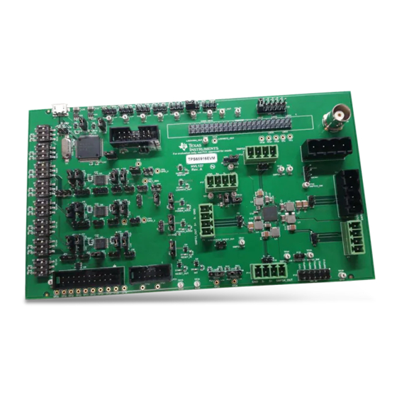
Page 12: Composite - Top View
(PCB) and the component placement of the EVM. Figure 7. Composite - Top View TPS65916 EVM User’s Guide SLIU021 – September 2016 Submit Documentation Feedback Copyright © 2016, Texas Instruments Incorporated... -
Page 13: Top Layer
Schematics, Bill of Materials, and Layout www.ti.com Figure 8. Top Layer Figure 9. Layer 1 GND SLIU021 – September 2016 TPS65916 EVM User’s Guide Submit Documentation Feedback Copyright © 2016, Texas Instruments Incorporated... -
Page 14: Layer 2 Signal
Schematics, Bill of Materials, and Layout www.ti.com Figure 10. Layer 2 SIGNAL Figure 11. Layer 3 POWER TPS65916 EVM User’s Guide SLIU021 – September 2016 Submit Documentation Feedback Copyright © 2016, Texas Instruments Incorporated... -
Page 15: Bottom Layer
Schematics, Bill of Materials, and Layout www.ti.com Figure 12. Bottom Layer Figure 13. Composite - Bottom View SLIU021 – September 2016 TPS65916 EVM User’s Guide Submit Documentation Feedback Copyright © 2016, Texas Instruments Incorporated... -
Page 16: Default Gpio Configuration
Figure TPS65916EVM Graphical User Interface (GUI) The GUI for TPS65916EVM gives the user the ability to interact with the internal registers of the device while also allowing control of some input pins. The GUI can be downloaded from TI.com. The TPS65916EVM GUI has three pages. The first page is labeled DUT Config, the second page is labeled Low Level Configuration, and the third page is labeled About. - Page 17 If writes should not be immediate, change the write type using the Update Mode pulldown to Deferred, change the bits to the desired value, and click the Write Register icon SLIU021 – September 2016 TPS65916 EVM User’s Guide Submit Documentation Feedback Copyright © 2016, Texas Instruments Incorporated...
- Page 18 SMPS1 to 1.15 V and then turns on SMPS3 to 1.25 V. These commands can run a power up and power down sequence quickly, eliminating the need to manually turn on all of the rails. TPS65916 EVM User’s Guide SLIU021 – September 2016 Submit Documentation Feedback Copyright © 2016, Texas Instruments Incorporated...
- Page 19 Revision History www.ti.com Figure 17. Sample Script Revision History DATE REVISION NOTES September 2016 Initial Release SLIU021 – September 2016 Revision History Submit Documentation Feedback Copyright © 2016, Texas Instruments Incorporated...
- Page 20 STANDARD TERMS AND CONDITIONS FOR EVALUATION MODULES Delivery: TI delivers TI evaluation boards, kits, or modules, including any accompanying demonstration software, components, or documentation (collectively, an “EVM” or “EVMs”) to the User (“User”) in accordance with the terms and conditions set forth herein. Acceptance of the EVM is expressly subject to the following terms and conditions.
- Page 21 FCC Interference Statement for Class B EVM devices NOTE: This equipment has been tested and found to comply with the limits for a Class B digital device, pursuant to part 15 of the FCC Rules. These limits are designed to provide reasonable protection against harmful interference in a residential installation.
- Page 22 【無線電波を送信する製品の開発キットをお使いになる際の注意事項】 開発キットの中には技術基準適合証明を受けて いないものがあります。 技術適合証明を受けていないもののご使用に際しては、電波法遵守のため、以下のいずれかの 措置を取っていただく必要がありますのでご注意ください。 1. 電波法施行規則第6条第1項第1号に基づく平成18年3月28日総務省告示第173号で定められた電波暗室等の試験設備でご使用 いただく。 2. 実験局の免許を取得後ご使用いただく。 3. 技術基準適合証明を取得後ご使用いただく。 なお、本製品は、上記の「ご使用にあたっての注意」を譲渡先、移転先に通知しない限り、譲渡、移転できないものとします。 上記を遵守頂けない場合は、電波法の罰則が適用される可能性があることをご留意ください。 日本テキサス・イ ンスツルメンツ株式会社 東京都新宿区西新宿6丁目24番1号 西新宿三井ビル 3.3.3 Notice for EVMs for Power Line Communication: Please see http://www.tij.co.jp/lsds/ti_ja/general/eStore/notice_02.page 電力線搬送波通信についての開発キットをお使いになる際の注意事項については、次のところをご覧くださ い。http://www.tij.co.jp/lsds/ti_ja/general/eStore/notice_02.page SPACER EVM Use Restrictions and Warnings: 4.1 EVMS ARE NOT FOR USE IN FUNCTIONAL SAFETY AND/OR SAFETY CRITICAL EVALUATIONS, INCLUDING BUT NOT LIMITED TO EVALUATIONS OF LIFE SUPPORT APPLICATIONS.
- Page 23 Notwithstanding the foregoing, any judgment may be enforced in any United States or foreign court, and TI may seek injunctive relief in any United States or foreign court. Mailing Address: Texas Instruments, Post Office Box 655303, Dallas, Texas 75265 Copyright © 2015, Texas Instruments Incorporated...
- Page 24 IMPORTANT NOTICE Texas Instruments Incorporated and its subsidiaries (TI) reserve the right to make corrections, enhancements, improvements and other changes to its semiconductor products and services per JESD46, latest issue, and to discontinue any product or service per JESD48, latest issue.
Need help?
Do you have a question about the TPS65916EVM and is the answer not in the manual?
Questions and answers