Table of Contents
Advertisement
Quick Links
www.ti.com
User's Guide
TPS65988 Evaluation Module
This document is the user guide for the TPS65988 Evaluation Module (TPS65988EVM). The TPS65988EVM
allows for evaluation of the TPS65988 IC as part of a stand-alone testing kit and for development and testing of
USB Type-C and Power Delivery (PD) end products. Out of the box, the TPS65988EVM is configured to emulate
a dual-port laptop computer. Both ports can be used to source or sink power, and both are dual-role ports (DRP)
but only support data as a downstream-facing port (DFP) host. When different configurations are required to test
your system, use the TPS65988 Application Configuration software tool to create a configuration or load a
different configuration template (see
DisplayPort
™
(DP) and a USB HUB (TUSB8020) to route USB signals to the appropriate port A or port A (port
A/B). The control MUX and USB HUB are connected to a SuperSpeed (SS) MUX (TUSB546) which routes the
appropriate DP lanes and USB 3.0 signals according to cable orientation and Alternate Mode selection.
1-2
highlights these features.
SLVUB62B – JUNE 2017 – REVISED NOVEMBER 2020
Submit Document Feedback
ABSTRACT
Figure
1-1). The TPS65988EVM uses a control MUX (HD3SS3412) to route
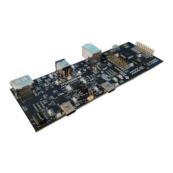
Figure 1-1. TPS65988EVM
Copyright © 2020 Texas Instruments Incorporated
Figure
TPS65988 Evaluation Module
1
Advertisement
Table of Contents

Related Manuals for Texas Instruments TPS65988


Summary of Contents for Texas Instruments TPS65988
-
Page 1: Figure 1-1. Tps65988Evm
This document is the user guide for the TPS65988 Evaluation Module (TPS65988EVM). The TPS65988EVM allows for evaluation of the TPS65988 IC as part of a stand-alone testing kit and for development and testing of USB Type-C and Power Delivery (PD) end products. Out of the box, the TPS65988EVM is configured to emulate a dual-port laptop computer. -
Page 2: Table Of Contents
MUX_CTR source L0-2 DP0-3 TUSB546 USB2 C_SSTX source USB3 Copyright © 2017, Texas Instruments Incorporated Figure 1-2. TPS65988EVM Block Diagram Table of Contents 1 About this Manual...................................5 2 Information About Cautions and Warnings..........................5 3 Items Required for Operation..............................Introduction.....................................5 Setup......................................6 5.1 Switch, Push Button, Connector, and Test Point Descriptions................... - Page 3 List of Figures Figure 1-1. TPS65988EVM................................1 Figure 1-2. TPS65988EVM Block Diagram..........................Figure 5-1. TPS65988 Jumper Configuration..........................Figure 5-2. TPS65988 Jumper Configuration Net Names......................Figure 5-3. TPS65987D Jumper Configuration........................... Figure 5-4. TPS65987D Jumper Configuration Net Names......................Figure 5-5. TPS65987S Jumper Configuration..........................9 Figure 5-6.
- Page 4 Total Phase, Incorporated. DisplayPort ™ are trademarks of Video Electronics Standards Association. BoosterPack ™ is a trademark of Texas Instruments. FTDI ® and Future Technology Devices International ® , are registered trademarks of Future Technology Devices International Limited.
-
Page 5: About This Manual
Notebook with USB 2.0, USB 3.0, and DP capabilities 4 Introduction The TPS65988 is a stand-alone USB Type-C and Power Delivery (PD) controller providing cable plug and orientation detection at the USB Type-C connector. Upon cable plug and orientation detection, the TPS65988 communicates on the CC line using the USB PD protocol. -
Page 6: Setup
5.1.1 Power Path Jumper Configuration The TPS65988EVM allows for analysis of TPS65987D and TPS65987S platforms through the adjustment of jumpers on J11 and J12. TPS65988 Evaluation Module SLVUB62B – JUNE 2017 – REVISED NOVEMBER 2020 Submit Document Feedback Copyright © 2020 Texas Instruments Incorporated... -
Page 7: Figure 5-1. Tps65988 Jumper Configuration
Setup 5.1.1.1 TPS65988 Jumper Configuration Out of the box, the TPS65988EVM has jumper configuration for a TPS65988 device. With this configuration, the two internal power paths are configured as Source paths for their respective Type-C ports. The two external power paths are configured as Sink paths for their respective Type-C ports. When using the TPS65988EVM, use a TPS65988 template in the TPS6598x Application Customization Tool. -
Page 8: Figure 5-3. Tps65987D Jumper Configuration
PPHV2 is used as the Source path for the Type-C port, it is connected to the net B-Var which is the Variable DC/DC used for Port B in the TPS65988 configuration. PPHV1 is used for the Sink path on the TPS65987D. -
Page 9: Figure 5-5. Tps65987S Jumper Configuration
TPS65987S, the internal power path (PPHV1) is used as the Source Path and one of the external power paths is used as the sink path. The TPS65988 can be configured to act as a TPS65987S through the use of a TPS65987S Configuration Template in the TPS6598x Application Customization Tool. -
Page 10: Figure 5-6. Tps65987S Jumper Configuration Net
HD3SS3412 Port B BDP0 BDP1 TUSB546 BDP2 BDP3 Copyright © 2017, Texas Instruments Incorporated Figure 5-8. DisplayPort ™ Source Block Diagram TPS65988 Evaluation Module SLVUB62B – JUNE 2017 – REVISED NOVEMBER 2020 Submit Document Feedback Copyright © 2020 Texas Instruments Incorporated... -
Page 11: Figure 5-9. Displayport Source Receptacle
S1 is located on the top-left corner of the EVM. This switch is a push-button that pulls the HRESET pin (39) of the TPS65988 high when pressed. Releasing the push-button pulls HRESET low again, and the TPS65988 goes through a soft reset, which consists of reloading firmware (FW) from RAM. If a... -
Page 12: Figure 5-12. Spi-Miso Pull Down Switch
S6 is located on the top right corner of the EVM. This push button switch holds the SPI Miso line to GND. This button is to be used when booting the device. If this button is pressed when the device is booting, the TPS65988 does not load its configuration from the SPI Flash, but instead boots into a default ROM configuration. -
Page 13: Figure 5-14. Ftdi Dip Switch (S3)
The TPS65988EVM has a dip switch (S2) that can be used to configure the I C addresses and BusPower settings of the device. Switch1 through Switch3 are used to set the I2C address of the TPS65988 by adjusting the voltage divider seen at ADCIN2. Refer to the TPS65988 datasheet to see the different I C address configurations. -
Page 14: Figure 5-15. I2C And Buspower Dip Switch (S2)
PD contracts up to 60 W per port or 120 W, total. An appropriate power adapter greater than 120 W must TPS65988 Evaluation Module SLVUB62B – JUNE 2017 – REVISED NOVEMBER 2020 Submit Document Feedback Copyright © 2020 Texas Instruments Incorporated... -
Page 15: Figure 5-17. Barrel Jack (J1) Schematic
SHIELD POWER SHIELD SHIELD SENSE POWER JPD1135-509-7F 100k 11.0k Figure 5-17. Barrel Jack (J1) Schematic Figure 5-18. Barrel Jack (J1) SLVUB62B – JUNE 2017 – REVISED NOVEMBER 2020 TPS65988 Evaluation Module Submit Document Feedback Copyright © 2020 Texas Instruments Incorporated... -
Page 16: Figure 5-19. Barrel Jack Detect Schematic
The barrel jack voltage is sensed by a comparator, which drives GPIO1 (BJ_DETECT) on the TPS65988. By default, the Barrel Jack Detect is not enabled. To enable Barrel Jack Detect place R109 and refer to the TPS65988 Utilities Tool User Guide and TPS65988 Firmware User Guide. -
Page 17: Figure 5-22. Usb Type-B Receptacle (J11)
Setup Figure 5-22. USB Type-B Receptacle (J11) SLVUB62B – JUNE 2017 – REVISED NOVEMBER 2020 TPS65988 Evaluation Module Submit Document Feedback Copyright © 2020 Texas Instruments Incorporated... -
Page 18: Figure 5-23. Usb Type-C Receptacles (J2) Schematic
The TPS65988EVM has two full feature USB Type-C receptacles (port A/B) and routes VBUS, SSTX and SSRX pairs, SBU1 and SBU2 pairs, and D+ and D– signals. The TPS65988 device can be used in self-powered and bus-powered configurations for added flexibility. When self-powered, the EVM can provide up to 60 W (20 V, at 3 A) of power per port via the internal high voltage power path. -
Page 19: Figure 5-25. Usb Micro-B Receptacle (J9) Schematic
5.1.11 USB Micro B Connector (J9) J9, the micro-B receptacle connects the FTDI to the PC for the TPS65988 Customization GUI. Use a standard USB micro-B to Type-A cable to make this connection. The Debug Board Enable LED turns on when VBUS is present on the FTDI board. -
Page 20: Figure 5-27. Tp13 (5 V), Tp8 (3.3 V), And Tp12 (1.2 V)
C or SPI pins when powered. TI recommends leaving the FT4232 in reset by having the Force Enable switches (switch 1 and switch 2) in the disabled (up) position. TPS65988 Evaluation Module SLVUB62B – JUNE 2017 – REVISED NOVEMBER 2020 Submit Document Feedback Copyright © 2020 Texas Instruments Incorporated... -
Page 21: Figure 5-28. Aardvark Connector (J10) Schematic
GND planes through multiple vias.Figure 5-30 highlights these features. Figure 5-30. TP10, TP11, TP15, TP16, TP17, TP18, TP9: GND Test Points SLVUB62B – JUNE 2017 – REVISED NOVEMBER 2020 TPS65988 Evaluation Module Submit Document Feedback Copyright © 2020 Texas Instruments Incorporated... -
Page 22: Figure 5-31. Tp1, Tp2, Tp3 And Tp4 - Cc1 And Cc2 Test Points
Figure 5-31 Figure 5-32 the highlight these features. Figure 5-31. TP1, TP2, TP3 and TP4 – CC1 and CC2 Test Points Figure 5-32. TPS65988 BMC Data TPS65988 Evaluation Module SLVUB62B – JUNE 2017 – REVISED NOVEMBER 2020 Submit Document Feedback... -
Page 23: Figure 5-33. Vbus Test Points: Tp14
VBUS test point is capable of drawing up to 3 A for an external load. Note that a PD power contract with the necessary capability must be negotiated in order to draw current from the VBUS test point. Refer to the TPS65988 Configuration Tool User Guide for configuration instructions. Figure 5-33... -
Page 24: Figure 5-35. A-Var, B-Var And System Power Test Points: Tp7, Tp6, And Tp5
Figure 5-35 highlights these features. Figure 5-35. A-Var, B-Var and System Power Test Points: TP7, TP6, and TP5 TPS65988 Evaluation Module SLVUB62B – JUNE 2017 – REVISED NOVEMBER 2020 Submit Document Feedback Copyright © 2020 Texas Instruments Incorporated... -
Page 25: Led Indicators Description
(GPIO); therefore, each must be enabled separately via configuration, if configuring a custom image (see TPS65988 Configuration Tool User Guide). By default MXCTL0 LED is on when the connected device supports USB3.0, MXCTL1 LED is on when DisplayPort Alternate Mode is entered. MXCTL2 highlights the orientation of the cable. -
Page 26: Figure 5-37. Mux Control Leds
USB 3.0 event D18 - MXCTL1 GPIO5 DP mode event D19 - MXCTL2 GPIO7 Cable orientation event D24 - PA_HPD GPIO3 TPS65988 Evaluation Module SLVUB62B – JUNE 2017 – REVISED NOVEMBER 2020 Submit Document Feedback Copyright © 2020 Texas Instruments Incorporated... -
Page 27: Figure 5-39. Pdo Port A/B Leds
D22 - PB_PDO0 GPIO_15 PDO TT bit 0 D5 - PA_VAR_DCDC GPIO_16 VAR-A enable D3 - PB_VAR_DCDC GPIO_17 VAR-B enable SLVUB62B – JUNE 2017 – REVISED NOVEMBER 2020 TPS65988 Evaluation Module Submit Document Feedback Copyright © 2020 Texas Instruments Incorporated... -
Page 28: Table 5-4. Pdo Led 0 And Pdo Led 1 Truth
19.78 V 5.2.3 S2 Switch Bank Functionality The I C address setting must match the configuration generated by the TPS65988 configuration tool. Table 5-5 summarizes the I C address settings. To adjust the dead battery boot behavior, the setting on ADCIN1 can be adjusted. -
Page 29: Using The Tps65988Evm
Out of the box, the TPS65988EVM is configured to emulate a dual-port laptop computer. Both ports are used to source or sink power, and both ports are data DFP. If different configurations are required to test your system, use the TPS65988 Application Configuration GUI tool to create a configuration or load a different configuration template. -
Page 30: Connecting The Evm
Using a USB Type-C to Type-A cable allows for connection to a legacy USB device, such as a flash-drive. The TPS65988 can act as a host passing the DP or USB connection by using the SS MUX and USB HUB. -
Page 31: Figure 7-2. Connecting Evm To Usb Type-C Devices
USB Type-C to Type-A Cable Flash Drive USB Type-C to DP/HDMI Dongle DP/HDMI Monitor TPS65988-EVM Figure 7-2. Connecting EVM to USB Type-C ™ Devices SLVUB62B – JUNE 2017 – REVISED NOVEMBER 2020 TPS65988 Evaluation Module Submit Document Feedback Copyright © 2020 Texas Instruments Incorporated... - Page 32 USB Type-C flash drive to the other USB Type-C port on the TPS65988EVM. The monitor displays what is present from the DP source. The flash drive enumerates on the windows PC. Table 7-1 explains this test setup. TPS65988 Evaluation Module SLVUB62B – JUNE 2017 – REVISED NOVEMBER 2020 Submit Document Feedback Copyright © 2020 Texas Instruments Incorporated...
-
Page 33: Table 7-1. Displayport And Usb Test Setup
A/B with a USB Type-C to DP cable. USB can be connected to Port A/B directly with a Type-C Flash Drive SLVUB62B – JUNE 2017 – REVISED NOVEMBER 2020 TPS65988 Evaluation Module Submit Document Feedback Copyright © 2020 Texas Instruments Incorporated... - Page 34 PC, it is confirmed that USB data is functioning properly. USB 3.0 data can be confirmed by observing LED MUX_CTRL0 in the high state. TPS65988 Evaluation Module SLVUB62B – JUNE 2017 – REVISED NOVEMBER 2020 Submit Document Feedback Copyright © 2020 Texas Instruments Incorporated...
-
Page 35: Debugging The Evm
The following checks help resolve issues when connecting the EVM to another EVM or USB Type-C device and no status LEDs are on: • Verify that a firmware image is loaded in on the TPS65988 using the TPS65988 Configuration Tool • Verify the CC lines are toggling for Dual-Role Port functionality (see... -
Page 36: Figure 7-5. Usb Type-C Connection And Pd Negotiation
Check for a small spike on VBUS during a plug event to verify that the PP_HV or PP_EXT switch is closed and is then opened, once an overcurrent condition is detected. Figure 7-5. USB Type-C ™ Connection and PD Negotiation TPS65988 Evaluation Module SLVUB62B – JUNE 2017 – REVISED NOVEMBER 2020 Submit Document Feedback Copyright © 2020 Texas Instruments Incorporated... -
Page 37: Reach Compliance
In compliance with the Article 33 provision of the EU REACH regulation, the user is notified that this EVM includes component(s) containing at least one Substance of Very High Concern (SVHC) above 0.1%. The substance use from Texas Instruments does not exceed 1 ton per year. The SVHCs are shown in Table 8-1. -
Page 38: Tps65988Evm Schematic
MUX_CTR source L0-2 DP0-3 TUSB546 USB2 C_SSTX source USB3 Copyright © 2017, Texas Instruments Incorporated Figure 9-1. TPS65988EVM Block Diagram TPS65988 Evaluation Module SLVUB62B – JUNE 2017 – REVISED NOVEMBER 2020 Submit Document Feedback Copyright © 2020 Texas Instruments Incorporated... -
Page 39: Figure 9-2. Tps65988Evm Processor Block
USB Type-C PD controller and contains connections for GPIOs, D+ and D-, CC1 and CC2, HRESET, I C lines, SPI for flash memory, and ADC1 and ADC2. Figure 9-2. TPS65988EVM Processor Block SLVUB62B – JUNE 2017 – REVISED NOVEMBER 2020 TPS65988 Evaluation Module Submit Document Feedback Copyright © 2020 Texas Instruments Incorporated... -
Page 40: Figure 9-3. Tps65988Evm Power Path Block
Figure 9-3 shows the power path block, which contains the power portion of the TPS65988 and the required passives. The external power path consists of back-to-back PMOS with RCP circuit. The internal power path is used for sourcing power and the external power path is used for sinking power. The TPS65988 power path can provide power to VBUS or consume power from VBUS. -
Page 41: Figure 9-4. Tps65988Evm Power Supply Block
SYS_PWR is 5 V; however, this also decreases VBUS maximum power capabilities. When using a lower voltage, the comparator circuit may have to be adjusted to trip at a lower voltage for proper barrel jack detection. Figure 9-4. TPS65988EVM Power Supply Block SLVUB62B – JUNE 2017 – REVISED NOVEMBER 2020 TPS65988 Evaluation Module Submit Document Feedback Copyright © 2020 Texas Instruments Incorporated... -
Page 42: Figure 9-5. Tps65988Evm Displayport Mux
DisplayPort Mux used to switch the DisplayPort signals to either USB Type-C Port. Figure 9-5. TPS65988EVM DisplayPort Mux TPS65988 Evaluation Module SLVUB62B – JUNE 2017 – REVISED NOVEMBER 2020 Submit Document Feedback Copyright © 2020 Texas Instruments Incorporated... -
Page 43: Figure 9-6. Tps65988Evm Ss Mux Block Port A
USB 3.1 data rates up to 5 Gbps and DP 1.4 up to 8.1 Gbps with 2 or 4 DP lanes. Figure 9-6. TPS65988EVM SS MUX Block Port A SLVUB62B – JUNE 2017 – REVISED NOVEMBER 2020 TPS65988 Evaluation Module Submit Document Feedback Copyright © 2020 Texas Instruments Incorporated... -
Page 44: Figure 9-7. Tps65988Evm Ss Mux Block Port B
USB 3.1 data rates up to 5 Gbps and DP 1.4 up to 8.1 Gbps with 2 or 4 DP lanes. Figure 9-7. TPS65988EVM SS MUX Block Port B TPS65988 Evaluation Module SLVUB62B – JUNE 2017 – REVISED NOVEMBER 2020 Submit Document Feedback Copyright © 2020 Texas Instruments Incorporated... -
Page 45: Figure 9-8. Tps65988Evm Usb Hub
Figure 9-8 shows the USB HUB, which contains the connections from the USB source receptacle. Figure 9-8. TPS65988EVM USB HUB SLVUB62B – JUNE 2017 – REVISED NOVEMBER 2020 TPS65988 Evaluation Module Submit Document Feedback Copyright © 2020 Texas Instruments Incorporated... -
Page 46: Figure 9-9. Tps65988Evm Usb Type-C Port-A Block
USB Type-C block, which includes the USB Type-C port A and ESD protection. Figure 9-9. TPS65988EVM USB Type-C ™ Port-A Block TPS65988 Evaluation Module SLVUB62B – JUNE 2017 – REVISED NOVEMBER 2020 Submit Document Feedback Copyright © 2020 Texas Instruments Incorporated... -
Page 47: Figure 9-10. Tps65988Evm Usb Type-C Port B Block
USB Type-C block, which includes the USB Type-C port B and ESD protection. Figure 9-10. TPS65988EVM USB Type-C ™ Port B Block SLVUB62B – JUNE 2017 – REVISED NOVEMBER 2020 TPS65988 Evaluation Module Submit Document Feedback Copyright © 2020 Texas Instruments Incorporated... -
Page 48: Figure 9-11. Tps65988Evm Ftdi Connector
Figure 9-11 shows the FTDI block, which contain the connections from the FTDI board. Figure 9-11. TPS65988EVM FTDI ® Connector Block TPS65988 Evaluation Module SLVUB62B – JUNE 2017 – REVISED NOVEMBER 2020 Submit Document Feedback Copyright © 2020 Texas Instruments Incorporated... -
Page 49: Figure 9-12. Tps65988Evm Current Sense Block Port A
VBUS and VIN_3V3 for port A and port B. Figure 9-12. TPS65988EVM Current Sense Block Port A Figure 9-13. TPS65988EVM Current Sense Block Port B SLVUB62B – JUNE 2017 – REVISED NOVEMBER 2020 TPS65988 Evaluation Module Submit Document Feedback Copyright © 2020 Texas Instruments Incorporated... -
Page 50: Figure 9-14. Tps65988Evm Boosterpack Header
Figure 9-14 shows the BoosterPack headers block, which contain the connections to the BoosterPack headers. Figure 9-14. TPS65988EVM BoosterPack Header Block TPS65988 Evaluation Module SLVUB62B – JUNE 2017 – REVISED NOVEMBER 2020 Submit Document Feedback Copyright © 2020 Texas Instruments Incorporated... -
Page 51: Tps65988Evm Board Layout
Figure 10-1. TPS65988EVM Top Overlay Figure 10-2. TPS65988EVM Solder Figure 10-3. TPS65988EVM Top Layer SSTXRX1 Figure 10-4. TPS65988EVM GND Plane 1 SLVUB62B – JUNE 2017 – REVISED NOVEMBER 2020 TPS65988 Evaluation Module Submit Document Feedback Copyright © 2020 Texas Instruments Incorporated... -
Page 52: Figure 10-5. Tps65988Evm High Speed
Figure 10-5. TPS65988EVM High Speed Figure 10-6. TPS65988EVM GND Plane 2 Figure 10-7. TPS65988EVM Power 1 Figure 10-8. TPS65988EVM Power 2 TPS65988 Evaluation Module SLVUB62B – JUNE 2017 – REVISED NOVEMBER 2020 Submit Document Feedback Copyright © 2020 Texas Instruments Incorporated... -
Page 53: Figure 10-9. Tps65988Evm Gnd Plane 3
Figure 10-9. TPS65988EVM GND Plane 3 Figure 10-10. TPS65988EVM SSTXRX2 Figure 10-11. TPS65988EVM Solder Mask Figure 10-12. TPS65988EVM Bottom Layer Component View SLVUB62B – JUNE 2017 – REVISED NOVEMBER 2020 TPS65988 Evaluation Module Submit Document Feedback Copyright © 2020 Texas Instruments Incorporated... -
Page 54: Tps65988Evm Bill Of Materials
Murata C53, C54, C62, C63 47uF CAP, TA, 47 µF, 35 V, +/- 10%, 0.3 ohm, SMD 7343-43 T521X107M025ATE060 Kemet TPS65988 Evaluation Module SLVUB62B – JUNE 2017 – REVISED NOVEMBER 2020 Submit Document Feedback Copyright © 2020 Texas Instruments Incorporated... - Page 55 White LED, White, SMD 0402, White LW QH8G-Q2S2-3K5L-1 OSRAM D18_PA_SS, D18_PB_SS, D19_PA_SS, D19_PB_SS, D20, D21, D22, D23, D24, D25, D26 SLVUB62B – JUNE 2017 – REVISED NOVEMBER 2020 TPS65988 Evaluation Module Submit Document Feedback Copyright © 2020 Texas Instruments Incorporated...
- Page 56 RES, 3.83 k, 1%, 0.05 W, 0201 0201 CRCW02013K83FKED Vishay-Dale R7, R8 10.0k RES, 10.0 k, 1%, 0.05 W, 0201 0201 MCR006YRTF1002 Rohm TPS65988 Evaluation Module SLVUB62B – JUNE 2017 – REVISED NOVEMBER 2020 Submit Document Feedback Copyright © 2020 Texas Instruments Incorporated...
- Page 57 R308, R309, R310, R312, R313, R314, R323, R324, R325, R326 191k RES, 191 k, 1%, 0.05 W, 0201 0201 RC0201FR-07191KL Yageo America SLVUB62B – JUNE 2017 – REVISED NOVEMBER 2020 TPS65988 Evaluation Module Submit Document Feedback Copyright © 2020 Texas Instruments Incorporated...
- Page 58 RES, 10.0 k, 1%, 0.1 W, 0603 0603 RC0603FR-0710KL Yageo America R195 1.00k RES, 1.00 k, 1%, 0.1 W, 0603 0603 CRCW06031K00FKEA Vishay-Dale TPS65988 Evaluation Module SLVUB62B – JUNE 2017 – REVISED NOVEMBER 2020 Submit Document Feedback Copyright © 2020 Texas Instruments Incorporated...
- Page 59 U13_PA_CS, High-Accuracy, Wide Common-Mode Range, Bidirectional DGK0008A INA284AIDGKR Texas Instruments INA284AIDGKT Texas Instruments U13_PB_CS Current Shunt Monitors, Zero-Drift Series, DGK0008A SLVUB62B – JUNE 2017 – REVISED NOVEMBER 2020 TPS65988 Evaluation Module Submit Document Feedback Copyright © 2020 Texas Instruments Incorporated...
- Page 60 RES, 39 k, 5%, 0.063 W, 0402 0402 CRCW040239K0JNED Vishay-Dale R115 560k RES, 560 k, 5%, 0.063 W, 0402 0402 CRCW0402560KJNED Vishay-Dale TPS65988 Evaluation Module SLVUB62B – JUNE 2017 – REVISED NOVEMBER 2020 Submit Document Feedback Copyright © 2020 Texas Instruments Incorporated...
- Page 61 Notes: Unless otherwise noted in the Alternate Part Number or Alternate Manufacturer columns, all parts may be substituted with equivalents. SLVUB62B – JUNE 2017 – REVISED NOVEMBER 2020 TPS65988 Evaluation Module Submit Document Feedback Copyright © 2020 Texas Instruments Incorporated...
-
Page 62: Revision History
Changes from Revision * (June 2017) to Revision A (June 2018) Page • Overall rework of this user's guide for revision A from Section 4 Section 9............5 TPS65988 Evaluation Module SLVUB62B – JUNE 2017 – REVISED NOVEMBER 2020 Submit Document Feedback Copyright © 2020 Texas Instruments Incorporated... - Page 63 STANDARD TERMS FOR EVALUATION MODULES Delivery: TI delivers TI evaluation boards, kits, or modules, including any accompanying demonstration software, components, and/or documentation which may be provided together or separately (collectively, an “EVM” or “EVMs”) to the User (“User”) in accordance with the terms set forth herein.
- Page 64 www.ti.com Regulatory Notices: 3.1 United States 3.1.1 Notice applicable to EVMs not FCC-Approved: FCC NOTICE: This kit is designed to allow product developers to evaluate electronic components, circuitry, or software associated with the kit to determine whether to incorporate such items in a finished product and software developers to write software applications for use with the end product.
- Page 65 www.ti.com Concernant les EVMs avec antennes détachables Conformément à la réglementation d'Industrie Canada, le présent émetteur radio peut fonctionner avec une antenne d'un type et d'un gain maximal (ou inférieur) approuvé pour l'émetteur par Industrie Canada. Dans le but de réduire les risques de brouillage radioélectrique à...
- Page 66 www.ti.com EVM Use Restrictions and Warnings: 4.1 EVMS ARE NOT FOR USE IN FUNCTIONAL SAFETY AND/OR SAFETY CRITICAL EVALUATIONS, INCLUDING BUT NOT LIMITED TO EVALUATIONS OF LIFE SUPPORT APPLICATIONS. 4.2 User must read and apply the user guide and other available documentation provided by TI regarding the EVM prior to handling or using the EVM, including without limitation any warning or restriction notices.
- Page 67 Notwithstanding the foregoing, any judgment may be enforced in any United States or foreign court, and TI may seek injunctive relief in any United States or foreign court. Mailing Address: Texas Instruments, Post Office Box 655303, Dallas, Texas 75265 Copyright © 2019, Texas Instruments Incorporated...
- Page 68 TI products. TI’s provision of these resources does not expand or otherwise alter TI’s applicable warranties or warranty disclaimers for TI products. Mailing Address: Texas Instruments, Post Office Box 655303, Dallas, Texas 75265 Copyright © 2020, Texas Instruments Incorporated...
- Page 69 Mouser Electronics Authorized Distributor Click to View Pricing, Inventory, Delivery & Lifecycle Information: Texas Instruments TPS65988DJEVM...
Need help?
Do you have a question about the TPS65988 and is the answer not in the manual?
Questions and answers