Advertisement
Quick Links
www.ti.com
EVM User's Guide: TPS65987DDKEVM
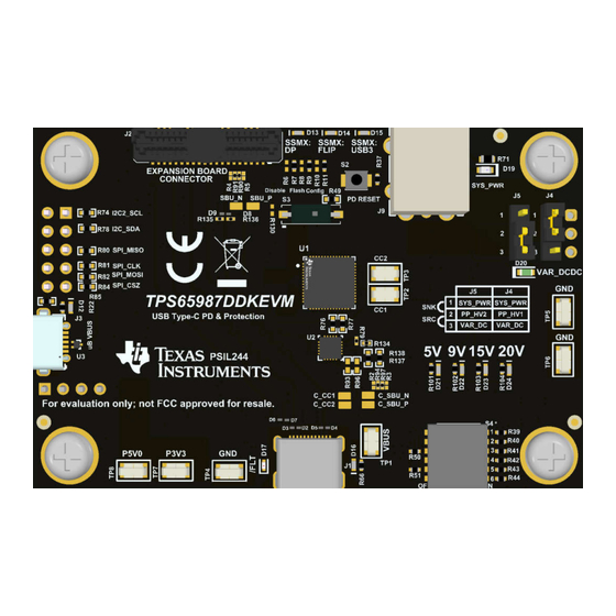
TPS65987DDK Evaluation Module
Description
The TPS65987DDKEVM allows for evaluation of
the TPS65987DDK IC as part of a stand-alone
testing kit for development and testing of USB
Type-C
®
and Power Delivery (PD) end products.
The TPS65987DDKEVM includes several devices
for complete evaluation of voltage protection, power
topology, and flashing. The TPS65987DDK integrates
fully managed power paths with robust protection for a
complete USB-C
®
PD design.
Get Started
1. Order the
TPS65987DDKEVM
2. Read the TPS65987DDKEVM User's Guide.
3. Start development with the
Customization
Tool.
4. Refer to the
TPS6598x Application Customization
Tool
user's guide,
data
Reference Manual, or
Features
•
TPS65987DDK is a fully configurable USB PD
device controller:
– Ability to source and sink up to 20V/5A
– Alternate mode support
™
•
DisplayPort
– Control for external DC/DC supplies, high
speed data muxes, and other peripheral
devices through either GPIO or I2C
SLVUCS6 – AUGUST 2024
Submit Document Feedback
on ti.com.
TPS6598x Application
sheet, Technical
E2E
for questions/support.
TPS65987DDKEVM Board
Copyright © 2024 Texas Instruments Incorporated
– GUI tool to easily configure TPS65987DDK for
various applications:
– Power management
•
Power supply from 3.3V or VBUS source
•
3.3V LDO output for dead battery support
•
Integrated fully managed power paths
•
Integrated robust power path protection
•
USB Type-C Power Delivery (PD) Controller
– 13 configurable GPIOs
– USB PD 3.0 certified
– USB Type-C specification certified
– Cable attach and orientation detection
– Integrated VCONN switch physical layer and
policy engine
– 3.3V LDO output for dead battery support
– Power supply from 3.3V or VBUS source
– One I2C primary or secondary port
– One I2C primary only port
– One I2C secondary only port
Applications
•
Single board computer
•
Other
personal electronics
applications
•
Docking station
•
Flat panel monitor
TPS65987DDK Evaluation Module
Description
TPS6598X-CONFIG
and
industrial
1
Advertisement

Related Manuals for Texas Instruments TPS65987DDKEVM


Summary of Contents for Texas Instruments TPS65987DDKEVM
- Page 1 TPS65987DDK Evaluation Module – GUI tool to easily configure TPS65987DDK for Description various applications: TPS6598X-CONFIG The TPS65987DDKEVM allows for evaluation of – Power management the TPS65987DDK IC as part of a stand-alone • Power supply from 3.3V or VBUS source testing kit for development and testing of USB •...
- Page 2 The TPS65987DDK can also control an attached super-speed multiplexer via GPIO or I2C to simultaneously support USB3.0/3.1 data rates and DisplayPort video. This document is the user's guide for the TPS65987DDK evaluation module (TPS65987DDKEVM). 1.2 Kit Contents This EVM kit includes: •...
- Page 3 TPS65987DDK device enables the appropriate power path and configures alternate mode settings for external multiplexers. The TPS65987DDK device has two internal power paths that can be source or sink with current rating up to 5A. For more details on each device on the TPS65987DDKEVM, refer to Table 1-1.
- Page 4 EVM, or device. 2.3 Jumper Configuration Out of the box, the TPS65987DDKEVM is configured to use the PPHV1 as sink path (J4) and PPHV2 as source path (J5), which matches the configuration already programmed in the device. The recovery firmware is a full flash image that comes with the Application Customization tool and configures the EVM to match the described jumper configuration below.
- Page 5 TPS65987DDK power path: Jump pins 1-2 to sink on PP_HV1 (default) TPS65987DDK power path: Jump pins 2-3 to source on PP_HV2 (default) 2.4 Connector Functionality Table 2-2 lists the TPS65987DDKEVM connector and functionality. Table 2-2. Connector Functionality Designator Description USB Type-C connector; TI recommends using an active or e-marked USB Type-C cable.
- Page 6 Hardware www.ti.com 2.5 Test Points Table 2-3 lists the TPS65987DDKEVM test points. Table 2-3. Test Points Test Point Label Description VBUS voltage on the USB Type-C connector. Sourcing and sinking is always in reference to (Source to V or sink from V System side CC1.
- Page 7 Table 2-5 Table 2-6 lists the TPS65987DDKEVM switches. For S1, all six switches must be set to the ON position (to the right) for flashing a project and debugging. For S4 switch, EVM out of the box must have S4->4 (BP_WaitFor3V3_Internal) as on (right).
- Page 8 • Read and edit registers during run-time in Debug mode 3.2 Debugging the EVM The following checks can help resolve issues when connecting the TPS65987DDKEVM to another EVM or USB Type-C device and no status LEDs are on: • Make sure that a firmware image is loaded on the TPS65987DDKEVM, using the...
- Page 9 C_S S TX2_N V AR_DCDC P 5V0 C_S S RX1_N C_S S RX1_P P 3V3 TP D6S 300ARUKR Figure 4-1. USB Type-C and External Module Connectors SLVUCS6 – AUGUST 2024 TPS65987DDK Evaluation Module Submit Document Feedback Copyright © 2024 Texas Instruments Incorporated...
- Page 10 XOS C0 F_S YS _3V3 White OS C1 RS T 10.0k 10pF OS C0 WAKE 180pF TM4C123GH6PMTR 10.0k 10pF Figure 4-2. TIVA Device and Connector TPS65987DDK Evaluation Module SLVUCS6 – AUGUST 2024 Submit Document Feedback Copyright © 2024 Texas Instruments Incorporated...
- Page 11 Switch 6 On only --> BP_NoWait (0.76) S P I_CS Z S P I_MIS O ADCIN2 ADCIN1 R130 100k 100k Figure 4-3. USB PD Controller and Memory SLVUCS6 – AUGUST 2024 TPS65987DDK Evaluation Module Submit Document Feedback Copyright © 2024 Texas Instruments Incorporated...
- Page 12 PP_HV2 P P _HV2 DRAIN2 White DRAIN2 LDO_1V8 LDO_1V8 LDO_3V3 LDO_3V3 10uF 10uF P 3V3 VIN_3V3 10uF TPS65987DDKRSHR Figure 4-4. USB PD Power Paths TPS65987DDK Evaluation Module SLVUCS6 – AUGUST 2024 Submit Document Feedback Copyright © 2024 Texas Instruments Incorporated...
- Page 13 R104 10.0k 10.0k 10.0k 10.0k S YS _P WR P DO_0 P DO_1 P DO_2 P DO_3 220uF 100uF Figure 4-5. Variable DC/DC Controller SLVUCS6 – AUGUST 2024 TPS65987DDK Evaluation Module Submit Document Feedback Copyright © 2024 Texas Instruments Incorporated...
- Page 14 P GND TP S 2500DRCR R116 32.4k ILim s e t Ma x 1100mA Typ 900mA Min 700mA Figure 4-6. Buck and Boost DC/DC Convertors TPS65987DDK Evaluation Module SLVUCS6 – AUGUST 2024 Submit Document Feedback Copyright © 2024 Texas Instruments Incorporated...
- Page 15 Hardware Design Files 4.2 PCB Layouts Figure 4-7 Figure 4-18 illustrates the TPS65987DDKEVM PCB layers. Figure 4-7. Top Layer Figure 4-8. Top Layer Mask SLVUCS6 – AUGUST 2024 TPS65987DDK Evaluation Module Submit Document Feedback Copyright © 2024 Texas Instruments Incorporated...
- Page 16 Hardware Design Files www.ti.com Figure 4-9. Super Speed Layer 2 Figure 4-10. Super Speed Layer 1 TPS65987DDK Evaluation Module SLVUCS6 – AUGUST 2024 Submit Document Feedback Copyright © 2024 Texas Instruments Incorporated...
- Page 17 Hardware Design Files Figure 4-11. Power Signal Layer 2 Figure 4-12. Power Signal Layer 1 SLVUCS6 – AUGUST 2024 TPS65987DDK Evaluation Module Submit Document Feedback Copyright © 2024 Texas Instruments Incorporated...
- Page 18 Hardware Design Files www.ti.com Figure 4-13. High Speed Layer Figure 4-14. Ground Plane 3 TPS65987DDK Evaluation Module SLVUCS6 – AUGUST 2024 Submit Document Feedback Copyright © 2024 Texas Instruments Incorporated...
- Page 19 Hardware Design Files Figure 4-15. Ground Plane 2 Figure 4-16. Ground Plane 1 SLVUCS6 – AUGUST 2024 TPS65987DDK Evaluation Module Submit Document Feedback Copyright © 2024 Texas Instruments Incorporated...
- Page 20 Hardware Design Files www.ti.com Figure 4-17. Bottom Layer Figure 4-18. Bottom Layer Mask TPS65987DDK Evaluation Module SLVUCS6 – AUGUST 2024 Submit Document Feedback Copyright © 2024 Texas Instruments Incorporated...
- Page 21 Hardware Design Files 4.3 Bill of Materials Table 4-1 lists the TPS65987DDKEVM BOM Table 4-1. TPS65987DDKEVM Bill of Materials Alternate Designator Value Description Package Reference Part Number Manufacturer Alternate PartNumber Manufacturer !PCB1 Printed Circuit Board PSIL244 C1, C2, C3, C4, CAP, CERM, 0.01uF, 50V, +/- 10%, C0G/NP0,...
- Page 22 Hardware Design Files www.ti.com Table 4-1. TPS65987DDKEVM Bill of Materials (continued) Alternate Designator Value Description Package Reference Part Number Manufacturer Alternate PartNumber Manufacturer C65, C67, C69, CAP, CERM, 47uF, 6.3V, +/- 20%, X5R, 0603 0603 GRM188R60J476ME15D MuRata 47 uF Diode, Schottky, 40V, 10A, PowerDI5...
- Page 23 Hardware Design Files Table 4-1. TPS65987DDKEVM Bill of Materials (continued) Alternate Designator Value Description Package Reference Part Number Manufacturer Alternate PartNumber Manufacturer R12, R13, R14 RES, 10.0 k, 1%, 0.063 W, AEC-Q200 Grade 0, 0402 CRCW040210K0FKED Vishay-Dale 10.0 k...
- Page 24 Hardware Design Files www.ti.com Table 4-1. TPS65987DDKEVM Bill of Materials (continued) Alternate Designator Value Description Package Reference Part Number Manufacturer Alternate PartNumber Manufacturer RES, 19.1 k, 1%, 0.063 W, AEC-Q200 Grade 0, 0402 CRCW040219K1FKED Vishay-Dale 19.1 k 0402 RES, 17.4 k, 1%, 0.063 W, AEC-Q200 Grade 0,...
- Page 25 Hardware Design Files Table 4-1. TPS65987DDKEVM Bill of Materials (continued) Alternate Designator Value Description Package Reference Part Number Manufacturer Alternate PartNumber Manufacturer 2.2V to 36V, microPower Comparator, DBV0005A DBV0005A TLV1701AIDBVR Texas Instruments TLV1701AIDBVT Texas Instruments (SOT-23-5) U7, U9 22V Precision Surge Protection Clamp,...
- Page 26 Video Electronics Standards Association. USB Type-C ® and USB-C ® are registered trademarks of USB Implementers Forum. All trademarks are the property of their respective owners. TPS65987DDK Evaluation Module SLVUCS6 – AUGUST 2024 Submit Document Feedback Copyright © 2024 Texas Instruments Incorporated...
- Page 27 STANDARD TERMS FOR EVALUATION MODULES Delivery: TI delivers TI evaluation boards, kits, or modules, including any accompanying demonstration software, components, and/or documentation which may be provided together or separately (collectively, an “EVM” or “EVMs”) to the User (“User”) in accordance with the terms set forth herein.
- Page 28 www.ti.com Regulatory Notices: 3.1 United States 3.1.1 Notice applicable to EVMs not FCC-Approved: FCC NOTICE: This kit is designed to allow product developers to evaluate electronic components, circuitry, or software associated with the kit to determine whether to incorporate such items in a finished product and software developers to write software applications for use with the end product.
- Page 29 www.ti.com Concernant les EVMs avec antennes détachables Conformément à la réglementation d'Industrie Canada, le présent émetteur radio peut fonctionner avec une antenne d'un type et d'un gain maximal (ou inférieur) approuvé pour l'émetteur par Industrie Canada. Dans le but de réduire les risques de brouillage radioélectrique à...
- Page 30 www.ti.com EVM Use Restrictions and Warnings: 4.1 EVMS ARE NOT FOR USE IN FUNCTIONAL SAFETY AND/OR SAFETY CRITICAL EVALUATIONS, INCLUDING BUT NOT LIMITED TO EVALUATIONS OF LIFE SUPPORT APPLICATIONS. 4.2 User must read and apply the user guide and other available documentation provided by TI regarding the EVM prior to handling or using the EVM, including without limitation any warning or restriction notices.
- Page 31 Notwithstanding the foregoing, any judgment may be enforced in any United States or foreign court, and TI may seek injunctive relief in any United States or foreign court. Mailing Address: Texas Instruments, Post Office Box 655303, Dallas, Texas 75265 Copyright © 2023, Texas Instruments Incorporated...
- Page 32 TI products. TI’s provision of these resources does not expand or otherwise alter TI’s applicable warranties or warranty disclaimers for TI products. TI objects to and rejects any additional or different terms you may have proposed. IMPORTANT NOTICE Mailing Address: Texas Instruments, Post Office Box 655303, Dallas, Texas 75265 Copyright © 2024, Texas Instruments Incorporated...
Need help?
Do you have a question about the TPS65987DDKEVM and is the answer not in the manual?
Questions and answers